EP0121896A2 - Procédé pour et dispostif à cintrer des matériaux en forme de barre - Google Patents
Procédé pour et dispostif à cintrer des matériaux en forme de barre Download PDFInfo
- Publication number
- EP0121896A2 EP0121896A2 EP84103662A EP84103662A EP0121896A2 EP 0121896 A2 EP0121896 A2 EP 0121896A2 EP 84103662 A EP84103662 A EP 84103662A EP 84103662 A EP84103662 A EP 84103662A EP 0121896 A2 EP0121896 A2 EP 0121896A2
- Authority
- EP
- European Patent Office
- Prior art keywords
- bending
- crank
- mandrel
- slide
- slides
- Prior art date
- Legal status (The legal status is an assumption and is not a legal conclusion. Google has not performed a legal analysis and makes no representation as to the accuracy of the status listed.)
- Granted
Links
Images


Classifications
-
- B—PERFORMING OPERATIONS; TRANSPORTING
- B21—MECHANICAL METAL-WORKING WITHOUT ESSENTIALLY REMOVING MATERIAL; PUNCHING METAL
- B21D—WORKING OR PROCESSING OF SHEET METAL OR METAL TUBES, RODS OR PROFILES WITHOUT ESSENTIALLY REMOVING MATERIAL; PUNCHING METAL
- B21D11/00—Bending not restricted to forms of material mentioned in only one of groups B21D5/00, B21D7/00, B21D9/00; Bending not provided for in groups B21D5/00 - B21D9/00; Twisting
- B21D11/10—Bending specially adapted to produce specific articles, e.g. leaf springs
- B21D11/12—Bending specially adapted to produce specific articles, e.g. leaf springs the articles being reinforcements for concrete
-
- Y—GENERAL TAGGING OF NEW TECHNOLOGICAL DEVELOPMENTS; GENERAL TAGGING OF CROSS-SECTIONAL TECHNOLOGIES SPANNING OVER SEVERAL SECTIONS OF THE IPC; TECHNICAL SUBJECTS COVERED BY FORMER USPC CROSS-REFERENCE ART COLLECTIONS [XRACs] AND DIGESTS
- Y10—TECHNICAL SUBJECTS COVERED BY FORMER USPC
- Y10S—TECHNICAL SUBJECTS COVERED BY FORMER USPC CROSS-REFERENCE ART COLLECTIONS [XRACs] AND DIGESTS
- Y10S72/00—Metal deforming
- Y10S72/702—Overbending to compensate for springback
Definitions
- the invention relates to a method and an apparatus for bending rod-shaped materials such as e.g. Reinforcing steels, comprising at least one bending mandrel and a bending crank arranged rotatably around it.
- rod-shaped materials such as e.g. Reinforcing steels
- bending machines which comprise a bending table, on which bending plates or wings e.g. are hydraulically driven.
- the eccentric or bending crank which can be changed at a distance on the bending plate, bends around "the bending roller or mandrel of various diameters that can be plugged onto the axis.
- the rod or rods lie against a fixed roller and an abutment.
- the object of the present invention is to develop a method and a device of the type described in the introduction in such a way that a largely automatic bending process takes place, by means of which end products are made available which are highly accurate with regard to the desired final shape.
- the device should be of simple construction and easy to handle, so that even untrained personnel can operate it.
- the object is achieved in that the rod-shaped material is grasped and bent by two bending mandrels, a bending crank and a drive for these comprehensive sliding carriages in such a way that at least after the bending of a material end in the further bending processes, a section of the material alternately from one of the bending carriages is fixed immovably, while the bending carriage that is not holding the material bends or is displaced along the latter.
- the steel materials to be cold-formed by the bending machine cannot be moved during the bending in the machine, so that it is ensured that the materials obtain the desired geometry with a low tolerance.
- the bending slides are each fixed in the region of two legs of the material which describe an angle to one another, the fixed mandrel at the intersection of the legs fits inside and the Bending crank is positioned on the outside of the leg, which is angled from the longitudinal axis specified in the undeformed state of the material.
- the bending slides themselves are arranged in a single hydraulic circuit, both the sliding movement of the bending slides and the rotary movement of the bending cranks around the bending mandrels being able to take place completely independently of one another.
- a stress relief in the leg immovably held by a bending slide is achieved in that a rotation of the bending crank takes place such that a "Opening" takes place to an extent that corresponds approximately to the elastic deformation of the material. It has been found that turning the bending crank back by approx. 15 ° is almost sufficient for all steel materials of normal thickness that are normally to be deformed.
- a device in particular intended for carrying out the method described above, is characterized in that two bending mandrels and bending cranks and drives comprising drives which are displaceable along the material to be bent and along a preferably horizontally arranged working surface are provided, the bending slides being operable in such a way that one (first) the bending slide then the material immovable holds when another (second) bending slide is moved into a bending position and / or the material bends.
- the drive elements arranged in a hydraulic circuit for the translational movement of the bending slides and the rotary movement of the bending cranks are made according to the invention in such a way that the operating fluid coming from the pump only acts on the drive elements for the translational movement one after the other, in order to subsequently possibly drive the drive elements for the rotary movement of the bending cranks flow through.
- the elements can be activated completely independently of one another.
- the drive elements react very promptly to pressurization or pressure drop, so that there is a further certainty that the end shapes of the bent rod-shaped materials have the desired geometry with small tolerances.
- they include an eccentrically mounted roll mandrel, which is preferably held immovably in the desired position via two counter-rotating threads, so that regardless of the force acting on it, i.e. regardless of whether the roll mandrel makes a right or a left turn , it is ensured that an undesirable displacement does not occur.
- the roll mandrel itself is held by a cylindrical disk or rod projecting from a shaft connected to the hydraulic drive, the shaft axis coinciding with the axis of the bending mandrel.
- the roll mandrel is arranged on an eccentric disk which is connected to the bending crank by means of a pin.
- the eccentric disc can be rotated to be able to set different positions in relation to the mandrel.
- spacer elements such as block screws emanate from the eccentric disc, which supports the eccentric disc against an assigned surface of the bending crank.
- the thread of the pin of the eccentric disc is selected so that the eccentric disc should be tightened during the bending process, but this is compensated for by the spacer elements. This ensures that a set position of the bending roller is always maintained. This suggestion can also be implemented in other bending machines and is therefore a self-made suggestion.
- the bending mandrel itself preferably comprises a fixed mandrel to be provided with interchangeable attachments (bending templates), so that there is the advantage that there is a slight adaptation to different thicknesses of the materials.
- the device according to the invention can be used in e.g. B.
- a processing line can be used, which comprises a cutting device cutting the material and a buffer provided between this and that preferably in the form of a taxiway. This clearly results in another not negligible advantage in terms of throughput.
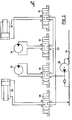
- a bending machine 10 is shown schematically in plan view, which comprises a horizontally lying processing table 12.
- two bending carriages 14 and 16 are slidably arranged in the longitudinal direction of the processing table 12, by means of which steel materials 18, preferably rod-shaped, to be introduced into the bending machine 10 are to be bent, as described in more detail below.
- These bars 18 enter the machine from a material store 20, wherein a plurality of bars 18 can be bent simultaneously by means of the bending slide 14 and 16.
- the material store 20 can be part of a processing line shown schematically in FIG. 3, which is arranged between the bending machine 10 and a bar cutting machine 22.
- the rod cutting machine can obey a principle as described in German patent application 32 06 673 by the same applicant.
- the bending machine 10 can be programmed via a keyboard 24 so as to cold-deform the materials 18 to the desired extent.
- the work surface 12 has a slot running vertically or almost vertically to accommodate several round materials to be arranged one above the other, which is laterally limited by the bending slides 14 and 16.
- a container 26 is also indicated, into which the bent materials 29 can be thrown by hand.
- an automatic ejection device is integrated in the machine 10.
- Each bending slide 14 or 16 consists of a bending crank 28, a bending mandrel 30 and a drive 32, 34, 36 and 38.
- the bending crank 28 moves at a distance around the bending mandrel 30. Between the bending crank 28 and the bending mandrel 30 there are then materials to be deformed.
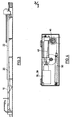
- the bending crank 28 comprises an eccentrically mounted roller mandrel 40, optionally rotatable about its axis, which is fixed immovably via two opposing threads 42 and 44 in the desired position (infinitely adjustable axis distance bending roller 40, bending mandrel 30), so that independently the bending mandrel 40 cannot be released from the direction of rotation of the bending crank 28.
- the bending crank 28 is also received eccentrically by a shaft 46 which is connected to one of the hydraulic cylinders 36 or 38.
- the longitudinal movement of the hydraulic cylinder 36 or 38 is converted into the desired rotary movement via a chain 48.
- the chain 48 cooperating with the shaft 46 is connected at one end to the hydraulic cylinder 36 or 38 and at the other end via a spring-biased element 50. The exact structure and the mode of operation can easily be seen from FIG. 4.
- the translatory movement takes place Movement of the bending slide 14 or 16 itself preferably via hydraulic motors 32 and 34 with a rotary output movement.
- Both the hydraulic cylinders 36 and 38 and the hydraulic motors 32 and 34 are, as is clearly shown in FIG. 2, according to the invention in a hydraulic circuit 52.
- This has the advantage that all drive means can be operated with a single unit, so that complex monitoring and control devices are not required. But even if only a single hydraulic circuit is required, it is nevertheless ensured that all drive means 32 to 38 can be operated completely independently of one another.
- the individual drive means 32, 34, 36, 38 in the circuit 52 are now arranged as follows.
- the first hydraulic motor 32 is located behind the pump 56 conveying the operating medium 54.
- the second hydraulic motor 34 is arranged in a circuit-like manner behind the first hydraulic motor 32. Then the hydraulic cylinders 38 and 36 follow to close the circuit.
- the connection between the circuit 52 and the drive elements 32 to 38 is made via solenoid valves 58, 60, 62 and 64. If all valves 58 to 64 are closed, the operating means 54 runs freely in the circuit 52. Now z.
- valve 60 If the valve 60 is activated in such a way that a connection to the hydraulic motor 32 takes place — consequently a connection PB / AT or PA / BT is established — the valves 62, 64 and 58 can otherwise flow back directly without pressure when the valves 62, 64 are not activated. However, if the valve 62 is also actuated, ie if both bending slides 14 and 16 are to be displaced at the same time, the hydraulic motor 34 is acted upon by the return fluid of the motor 32 without the independence of the actuation being canceled thereby. Accordingly, the return fluid of the engine 34 can act on the hydraulic cylinders 38/36.
- An essential feature of the invention is that during the bending process at least one section of the material 18 having an angled end is held between the mandrel and the bending crank in such a way that there is immovability when the material is bent with the other bending slide.
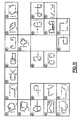
- a corresponding bending process will now be explained in more detail with reference to FIG. 6.
- the rod-shaped material 66 shown schematically in FIG. 6 is first angled at the left end 68, ie the bending crank 72 is rotated clockwise around the bending mandrel 70. In the angled state, the bending crank 72 therefore assumes the position 74. In this position, the end 68 between the mandrel 70 and the bending crank 74 is fixed immovably.
- the bending mandrel 70 is then located on the inside at the intersection of the legs of the material 66 that describe an angle to one another, and the bending crank 74 is located on the outside of the angled end section 68.
- the right end 76 of the material 66 can then be bent to the desired extent.
- a bending crank 78 is in turn rotated around a bending mandrel 80.
- the bending crank 78 returns to its starting position and the bending slide comprising the mandrel 80 and the bending crank 78.
- 82 is shifted from position B to position C.
- a bending process can then be carried out again, so that the material 66, viewed from its center 84, has the desired geometric shape with regard to its right side.
- the material 66 is then held in its upper position (reference numeral 86) by the bending slide 82 between the bending mandrel 18 and the bending crank 78.
- the bending slide 88 comprising the bending mandrel 70 and the bending crank 72 is actuated in such a way that the bending crank 74 is turned back into its starting position, so that the bending slide 88 can subsequently be moved from the position A to the position D.
- the bending crank 72 is then rotated around the bending mandrel 70 (reference number 90), so that the material 66 then has the desired bending shape.
- FIG. 7 and 8 show other bending shapes by way of example, the bending process being carried out in the corresponding sequence in steps D ', E, F, G, H, I, K, L and M, N, 0, P, R, S is done.
- the respective material is immovably fixed during the bending processes E, F, G, H or N, 0, P by the bending slide in the position D 'or M, whereas in the bending processes I, K and L or R and S it is set in the H or P position.
- the shaped materials are removed from the bending slide so that they can be moved back into their basic position, that is to say D ', E or M, N.
- FIG. 9 A bending process is schematically shown once again in FIG. 9, which corresponds to that of FIGS. 6 to 8 in the course of the method.
- the dashed representation of the right leg 92 should make it clear that when a closed figure is formed, relaxation takes place such that the leg 92 is moved to the right by turning the bending crank 94 back, so that when the left leg 96 is bent in the direction of the leg 92- an undesired further deformation of this cannot take place.
- the leg 92 is relaxed to the extent and thus the bending crank 94 is turned back, as corresponds to the elastic deformation. This ensures that overbending cannot occur when the leg ends 98 or 100 collide, so that the cold-formed end product also exhibits the desired geometry.
- the relaxation is basically dependent on the strength of the to be bent materials, but experience has shown that a turning back of the bending crank 94 to 15 0 induces relaxation, which ensures that almost all common materials normal strength which is excluded to avoid over bending .
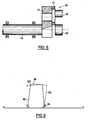
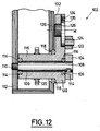
- FIG. 12 shows a particularly inventive design of a bending crank 102 that is rotatable about a bending mandrel 108.
- the bending mandrel 108 is the end of a fixed shaft 109, which in turn is arranged non-rotatably via a thread 110 in a section of the bending slide housing 112.
- Interchangeable bending templates 104 can be placed on the bending mandrel 108 and are held non-rotatably on the bending mandrel 108, for example, by means of a pan spring 106 or elements having the same effect.
- the bending crank 102 is now rotated about the shaft 109, the bending crank 102 being supported via a hollow cylinder section 116 via bearings 114 on the shaft 108 and via bearings 118 relative to the housing 112. Furthermore, the hollow cylinder section 116 has a drive pinion 120, via which the bending crank 102 is rotated in the manner described above.
- the bending bucket 102 now has a roller mandrel 122 eccentrically to the axis of rotation, which is firmly connected to an eccentric disk 126 via a pin 124.
- the roller mandrel 122 can be rotatably mounted about the pin 124.
- the mandrel 104 is arranged non-rotatably.
- the eccentric disk 126 is connected to a leg 132 protruding from the hollow cylinder 116 by means of an eccentric pin 136 , the thread of which is selected such that when the bending crank 102 is turned to bend the material 18 to be inserted between the roll mandrel 122 and the mandrel 108 or the bending template 104, it is tightened the eccentric disc 126 takes place without changing the position of the bending roller.
- spacing elements 134 protrude from the side of the eccentric disk facing the bending crank 102, by means of which the eccentric disk is fixed to the section 132 of the bending crank 102 facing away from it without play.
- the eccentric disk 126 is clamped when the pin 136 is non-positively locked by means of a roller mandrel 126 with the material 18 to be located between the latter and the bending template 128 (for example, the bending crank is rotated counterclockwise , the slope of the eccentric mandrel is right-hand).
- the bending crank 102 with the bending mandrel 122 is now rotated on a circle X 1 around the shaft 108 as the center point, the radius of the roller mandrel 120 depending on its position relative to the center point M being greater or smaller than X 1 .
- the radius X 2 is smaller than X 1
- the radius X 3 is larger than X 1 .
- the bending templates 128 and 130 can have different diameters.
- a counter bearing 136 is also shown in FIGS. 13 and 14 in order to hold the materials 18 in a horizontal position in the exemplary embodiment during bending with respect to the section not to be deformed.
Priority Applications (1)
| Application Number | Priority Date | Filing Date | Title |
|---|---|---|---|
| AT84103662T ATE30861T1 (de) | 1983-04-06 | 1984-04-04 | Verfahren und vorrichtung zum biegen von stabfoermigen materialien. |
Applications Claiming Priority (2)
| Application Number | Priority Date | Filing Date | Title |
|---|---|---|---|
| DE19833312397 DE3312397A1 (de) | 1983-04-06 | 1983-04-06 | Verfahren und vorrichtung zum biegen von stabfoermigen materialien |
| DE3312397 | 1983-04-06 |
Publications (4)
| Publication Number | Publication Date |
|---|---|
| EP0121896A2 true EP0121896A2 (fr) | 1984-10-17 |
| EP0121896A3 EP0121896A3 (en) | 1985-01-23 |
| EP0121896B1 EP0121896B1 (fr) | 1987-11-19 |
| EP0121896B2 EP0121896B2 (fr) | 1991-12-18 |
Family
ID=6195607
Family Applications (1)
| Application Number | Title | Priority Date | Filing Date |
|---|---|---|---|
| EP84103662A Expired - Lifetime EP0121896B2 (fr) | 1983-04-06 | 1984-04-04 | Procédé pour et dispostif à cintrer des matériaux en forme de barre |
Country Status (4)
| Country | Link |
|---|---|
| US (1) | US4702097A (fr) |
| EP (1) | EP0121896B2 (fr) |
| AT (1) | ATE30861T1 (fr) |
| DE (2) | DE3312397A1 (fr) |
Cited By (4)
| Publication number | Priority date | Publication date | Assignee | Title |
|---|---|---|---|---|
| WO1985005053A1 (fr) * | 1984-04-30 | 1985-11-21 | Howard Bruce | Appareil de fabrication d'etriers de renforcement de beton et leur soudage avec des tiges pour former une cage de renforcement de beton |
| EP0238026A1 (fr) | 1986-03-14 | 1987-09-23 | Ruhl, Heinz | Procédé et dispositif pour cintrer des matériaux en forme de barre |
| EP0334353A1 (fr) * | 1988-03-25 | 1989-09-27 | EVG Entwicklungs- u. Verwertungs- Gesellschaft m.b.H. | Procédé et machine pour plier de préférence du matériel en forme de barre |
| DE3919607A1 (de) * | 1989-06-15 | 1991-01-03 | Heinz Ruhl | Verfahren und vorrichtung zum biegen von stabfoermigem material |
Families Citing this family (10)
| Publication number | Priority date | Publication date | Assignee | Title |
|---|---|---|---|---|
| FR2657546B1 (fr) * | 1990-01-26 | 1992-05-22 | Eaton Leonard Picot Sa | Machine a cintrer les tubes a deux tetes de cintrage. |
| CA2100530A1 (fr) * | 1992-09-02 | 1994-03-03 | Michael W. Bogart | Dispositif pour courber des aiguilles |
| CA2106791A1 (fr) * | 1992-10-09 | 1994-04-10 | Michael W. Bogart | Dispositif de courbure d'aiguilles |
| US5388441A (en) * | 1992-12-29 | 1995-02-14 | United States Surgical Corporation | Needle curver with automatic feed |
| AT401360B (de) * | 1993-05-07 | 1996-08-26 | Progress Ag | Biegeanlage für stäbe |
| JP3685526B2 (ja) * | 1995-07-14 | 2005-08-17 | 臼井国際産業株式会社 | パイプの曲げ加工装置 |
| US5927132A (en) * | 1998-04-30 | 1999-07-27 | Schnell Spa | Method of bending bars |
| FR2900078B1 (fr) * | 2006-04-24 | 2008-06-13 | Numalliance Soc Par Actions Si | Machine de pliage de fil combinant un dispositif de faconnage sequentiel et un dispositif mettant en oeuvre une plaque d'outillages |
| JP4626623B2 (ja) * | 2007-03-12 | 2011-02-09 | トヨタ自動車株式会社 | 平角材のエッジワイズ曲げ加工方法、及び加工装置 |
| CN112720033B (zh) * | 2020-12-29 | 2022-04-12 | 新昌县三特自动化科技有限公司 | 微型轴承的全自动车削生产线 |
Citations (1)
| Publication number | Priority date | Publication date | Assignee | Title |
|---|---|---|---|---|
| DE3206673A1 (de) | 1982-02-25 | 1983-09-01 | Helmut 6230 Kriftel Zahlaus | Vorrichtung zum zuschneiden von stabfoermigen materialien |
Family Cites Families (11)
| Publication number | Priority date | Publication date | Assignee | Title |
|---|---|---|---|---|
| US1546147A (en) * | 1924-04-25 | 1925-07-14 | Frederick A C Skinner | Pipe-bending machine |
| US1769570A (en) * | 1927-12-28 | 1930-07-01 | Hudson Motor Car Co | Apparatus for shaping sheet metal |
| DE1552970B2 (de) * | 1965-04-24 | 1977-01-13 | Maschine zum biegen von versteifungsbuegeln, armierungseisen o.dgl. | |
| US3481177A (en) * | 1967-09-29 | 1969-12-02 | Lear Siegler Inc | Wire bending assembly |
| US3568300A (en) * | 1968-07-02 | 1971-03-09 | Zidell Explorations Inc | Method and apparatus for forming ship hulls |
| DE1752716A1 (de) * | 1968-07-05 | 1971-07-15 | Ernst Stegmann | Verfahren zum maschinellen Biegen von Draht- und Bandmaterial und Maschine zur Durchfuehrung des Verfahrens |
| US3803893A (en) * | 1971-08-17 | 1974-04-16 | P Peddinghaus | Process for multiple bending of rods and a bending machine for carrying out this process |
| US3805576A (en) * | 1972-08-18 | 1974-04-23 | Cyril Bath Co | High speed multi-bending machine |
| GB1463522A (en) * | 1974-09-11 | 1977-02-02 | Russel Bowen Systems Ltd | Bending machines |
| AT338071B (de) * | 1974-12-16 | 1977-07-25 | Evg Entwicklung Verwert Ges | Biegemaschine fur stabformiges material, insbesondere fur betonbewehrungsstabe |
| IT1137724B (it) * | 1981-07-10 | 1986-09-10 | Mec Montorfano Di Montorfano V | Unita' di curvatura per tubi e fili in metallo e procedimento di messa in esercizio dell'unita |
-
1983
- 1983-04-06 DE DE19833312397 patent/DE3312397A1/de not_active Withdrawn
-
1984
- 1984-04-04 EP EP84103662A patent/EP0121896B2/fr not_active Expired - Lifetime
- 1984-04-04 AT AT84103662T patent/ATE30861T1/de not_active IP Right Cessation
- 1984-04-04 DE DE8484103662T patent/DE3467519D1/de not_active Expired
-
1986
- 1986-03-14 US US06/839,688 patent/US4702097A/en not_active Expired - Fee Related
Patent Citations (1)
| Publication number | Priority date | Publication date | Assignee | Title |
|---|---|---|---|---|
| DE3206673A1 (de) | 1982-02-25 | 1983-09-01 | Helmut 6230 Kriftel Zahlaus | Vorrichtung zum zuschneiden von stabfoermigen materialien |
Cited By (7)
| Publication number | Priority date | Publication date | Assignee | Title |
|---|---|---|---|---|
| WO1985005053A1 (fr) * | 1984-04-30 | 1985-11-21 | Howard Bruce | Appareil de fabrication d'etriers de renforcement de beton et leur soudage avec des tiges pour former une cage de renforcement de beton |
| EP0238026A1 (fr) | 1986-03-14 | 1987-09-23 | Ruhl, Heinz | Procédé et dispositif pour cintrer des matériaux en forme de barre |
| EP0371960A2 (fr) * | 1986-03-14 | 1990-06-06 | Ruhl, Heinz | Procédé pour cintrer des matériaux en forme de barre |
| EP0371960A3 (en) * | 1986-03-14 | 1990-06-20 | Ruhl, Heinz | Method of and device for bending bar-shaped materials |
| EP0334353A1 (fr) * | 1988-03-25 | 1989-09-27 | EVG Entwicklungs- u. Verwertungs- Gesellschaft m.b.H. | Procédé et machine pour plier de préférence du matériel en forme de barre |
| WO1989009104A1 (fr) * | 1988-03-25 | 1989-10-05 | Evg Entwicklungs- Und Verwertungs-Gesellschaft M.B | Procede et dispositif de cintrage de materiaux, de preference sous forme de barres |
| DE3919607A1 (de) * | 1989-06-15 | 1991-01-03 | Heinz Ruhl | Verfahren und vorrichtung zum biegen von stabfoermigem material |
Also Published As
| Publication number | Publication date |
|---|---|
| ATE30861T1 (de) | 1987-12-15 |
| US4702097A (en) | 1987-10-27 |
| EP0121896A3 (en) | 1985-01-23 |
| EP0121896B1 (fr) | 1987-11-19 |
| DE3467519D1 (en) | 1987-12-23 |
| EP0121896B2 (fr) | 1991-12-18 |
| DE3312397A1 (de) | 1984-10-11 |
Similar Documents
| Publication | Publication Date | Title |
|---|---|---|
| EP0121896B1 (fr) | Procédé pour et dispostif à cintrer des matériaux en forme de barre | |
| DE3739173A1 (de) | Verfahren und vorrichtung zum biegen von werkstuecken | |
| CH648517A5 (de) | Vorrichtung zum abschneiden einer drahtwendel und zum umbiegen des wendelendes um die letzte wendelwindung herum. | |
| DE2802621A1 (de) | Metallblechformmaschine | |
| DE3016956A1 (de) | Planstanzmaschine | |
| AT402032B (de) | Maschine zum bearbeiten von gittermatten aus miteinander verschweissten längs- und querdrähten | |
| EP0622136A1 (fr) | Dispositif pour la fabrication de treillis d'armature pour panneaux en béton | |
| DE2164026A1 (de) | Biegevorrichtung und Verfahren zum Herstellen von Biegungen | |
| DE2456303A1 (de) | Verfahren und vorrichtungen zum kantenanformen an einer metallplatte | |
| DE4103134A1 (de) | Einrichtung zum herstellen von gebogenen abschnitten an einem rohr, insbesondere zur herstellung einer rohrschlange | |
| DE1602064B2 (de) | Walzwerk zum auswalzen eines metallrohlings | |
| DE3816005A1 (de) | Maschine zum biegen von rundeisen und aehnlichen metallelementen | |
| DE2940635C2 (de) | Profilstahlschere, -stanze o.dgl. | |
| DE1552148B2 (de) | Biegevorrichtung zum fortlaufenden umformen eines geraden drahtes in eine wellenfoermige feder mit in verschiedenen ebenen liegenden abschnitten | |
| DE10065255B4 (de) | Mehrstufenpresse | |
| EP0371960A2 (fr) | Procédé pour cintrer des matériaux en forme de barre | |
| DE750393C (de) | Vorrichtung zur AEnderung der Steghoehe eines mit Flanschen versehenen Profilstabes | |
| DE2630224A1 (de) | Verfahren zum montieren von streckwerken auf einer streckwerksbank | |
| DE3423052C2 (fr) | ||
| DE2223461A1 (de) | Vorrichtung zum richten und biegen von stabmaterial | |
| DE251470C (fr) | ||
| DE1552148C (de) | Biegevorrichtung zum fortlaufenden Umformen eines geraden Drahtes in eine wellenförmige Feder mit in verschiedenen Ebenen liegenden Abschnitten | |
| DE2432991C3 (de) | Vorrichtung zum Biegen einer vorgebogenen Strebenschlange für einen Leichtbauträger | |
| DE1452867A1 (de) | Press- und Reguliervorrichtung fuer Blechrichtmaschinen | |
| DE2317540A1 (de) | Vorrichtung zum streckbiegen von profilstraengen |
Legal Events
| Date | Code | Title | Description |
|---|---|---|---|
| PUAI | Public reference made under article 153(3) epc to a published international application that has entered the european phase |
Free format text: ORIGINAL CODE: 0009012 |
|
| AK | Designated contracting states |
Designated state(s): AT CH DE FR GB IT LI SE |
|
| PUAL | Search report despatched |
Free format text: ORIGINAL CODE: 0009013 |
|
| AK | Designated contracting states |
Designated state(s): AT CH DE FR GB IT LI SE |
|
| 17P | Request for examination filed |
Effective date: 19841228 |
|
| 17Q | First examination report despatched |
Effective date: 19860313 |
|
| R17C | First examination report despatched (corrected) |
Effective date: 19860904 |
|
| GRAA | (expected) grant |
Free format text: ORIGINAL CODE: 0009210 |
|
| AK | Designated contracting states |
Kind code of ref document: B1 Designated state(s): AT CH DE FR GB IT LI SE |
|
| REF | Corresponds to: |
Ref document number: 30861 Country of ref document: AT Date of ref document: 19871215 Kind code of ref document: T |
|
| REF | Corresponds to: |
Ref document number: 3467519 Country of ref document: DE Date of ref document: 19871223 |
|
| ITF | It: translation for a ep patent filed |
Owner name: STUDIO JAUMANN |
|
| GBT | Gb: translation of ep patent filed (gb section 77(6)(a)/1977) | ||
| ET | Fr: translation filed | ||
| PLBI | Opposition filed |
Free format text: ORIGINAL CODE: 0009260 |
|
| REG | Reference to a national code |
Ref country code: CH Ref legal event code: PUE Owner name: HEINZ RUHL |
|
| 26 | Opposition filed |
Opponent name: MUHR UND BENDER MASCHINENBAU GMBH Effective date: 19880507 |
|
| REG | Reference to a national code |
Ref country code: FR Ref legal event code: TP |
|
| ITPR | It: changes in ownership of a european patent |
Owner name: CESSIONE;RUHL, HEINZ |
|
| RIN2 | Information on inventor provided after grant (corrected) |
Free format text: ZAHLAUS, HELMUT |
|
| RAP2 | Party data changed (patent owner data changed or rights of a patent transferred) |
Owner name: RUHL, HEINZ |
|
| ITTA | It: last paid annual fee | ||
| PUAH | Patent maintained in amended form |
Free format text: ORIGINAL CODE: 0009272 |
|
| STAA | Information on the status of an ep patent application or granted ep patent |
Free format text: STATUS: PATENT MAINTAINED AS AMENDED |
|
| 27A | Patent maintained in amended form |
Effective date: 19911218 |
|
| AK | Designated contracting states |
Kind code of ref document: B2 Designated state(s): AT CH DE FR GB IT LI SE |
|
| REG | Reference to a national code |
Ref country code: CH Ref legal event code: AEN |
|
| ITF | It: translation for a ep patent filed |
Owner name: STUDIO JAUMANN |
|
| PGFP | Annual fee paid to national office [announced via postgrant information from national office to epo] |
Ref country code: SE Payment date: 19920331 Year of fee payment: 9 Ref country code: CH Payment date: 19920331 Year of fee payment: 9 |
|
| PGFP | Annual fee paid to national office [announced via postgrant information from national office to epo] |
Ref country code: GB Payment date: 19920406 Year of fee payment: 9 |
|
| PGFP | Annual fee paid to national office [announced via postgrant information from national office to epo] |
Ref country code: AT Payment date: 19920410 Year of fee payment: 9 |
|
| ET3 | Fr: translation filed ** decision concerning opposition | ||
| GBTA | Gb: translation of amended ep patent filed (gb section 77(6)(b)/1977) | ||
| PGFP | Annual fee paid to national office [announced via postgrant information from national office to epo] |
Ref country code: DE Payment date: 19920424 Year of fee payment: 9 |
|
| PGFP | Annual fee paid to national office [announced via postgrant information from national office to epo] |
Ref country code: FR Payment date: 19920429 Year of fee payment: 9 |
|
| PG25 | Lapsed in a contracting state [announced via postgrant information from national office to epo] |
Ref country code: GB Effective date: 19930404 Ref country code: AT Effective date: 19930404 |
|
| PG25 | Lapsed in a contracting state [announced via postgrant information from national office to epo] |
Ref country code: SE Effective date: 19930405 |
|
| PG25 | Lapsed in a contracting state [announced via postgrant information from national office to epo] |
Ref country code: LI Effective date: 19930430 Ref country code: CH Effective date: 19930430 |
|
| GBPC | Gb: european patent ceased through non-payment of renewal fee |
Effective date: 19930404 |
|
| PG25 | Lapsed in a contracting state [announced via postgrant information from national office to epo] |
Ref country code: FR Effective date: 19931229 |
|
| REG | Reference to a national code |
Ref country code: CH Ref legal event code: PL |
|
| PG25 | Lapsed in a contracting state [announced via postgrant information from national office to epo] |
Ref country code: DE Effective date: 19940101 |
|
| REG | Reference to a national code |
Ref country code: FR Ref legal event code: ST |
|
| EUG | Se: european patent has lapsed |
Ref document number: 84103662.7 Effective date: 19931110 |