EP0121844B1 - Robotergelenk - Google Patents
Robotergelenk Download PDFInfo
- Publication number
- EP0121844B1 EP0121844B1 EP84103246A EP84103246A EP0121844B1 EP 0121844 B1 EP0121844 B1 EP 0121844B1 EP 84103246 A EP84103246 A EP 84103246A EP 84103246 A EP84103246 A EP 84103246A EP 0121844 B1 EP0121844 B1 EP 0121844B1
- Authority
- EP
- European Patent Office
- Prior art keywords
- joint
- housing
- mounting flange
- motor
- robot
- Prior art date
- Legal status (The legal status is an assumption and is not a legal conclusion. Google has not performed a legal analysis and makes no representation as to the accuracy of the status listed.)
- Expired
Links
Images



Classifications
-
- B—PERFORMING OPERATIONS; TRANSPORTING
- B25—HAND TOOLS; PORTABLE POWER-DRIVEN TOOLS; MANIPULATORS
- B25J—MANIPULATORS; CHAMBERS PROVIDED WITH MANIPULATION DEVICES
- B25J17/00—Joints
- B25J17/02—Wrist joints
- B25J17/0241—One-dimensional joints
- B25J17/025—One-dimensional joints mounted in series
-
- B—PERFORMING OPERATIONS; TRANSPORTING
- B25—HAND TOOLS; PORTABLE POWER-DRIVEN TOOLS; MANIPULATORS
- B25J—MANIPULATORS; CHAMBERS PROVIDED WITH MANIPULATION DEVICES
- B25J9/00—Program-controlled manipulators
- B25J9/02—Program-controlled manipulators characterised by movement of the arms, e.g. cartesian coordinate type
- B25J9/04—Program-controlled manipulators characterised by movement of the arms, e.g. cartesian coordinate type by rotating at least one arm, excluding the head movement itself, e.g. cylindrical coordinate type or polar coordinate type
- B25J9/046—Revolute coordinate type
-
- B—PERFORMING OPERATIONS; TRANSPORTING
- B25—HAND TOOLS; PORTABLE POWER-DRIVEN TOOLS; MANIPULATORS
- B25J—MANIPULATORS; CHAMBERS PROVIDED WITH MANIPULATION DEVICES
- B25J9/00—Program-controlled manipulators
- B25J9/10—Program-controlled manipulators characterised by positioning means for manipulator elements
- B25J9/102—Gears specially adapted therefor, e.g. reduction gears
Definitions
- a reduction gear (harmonic drive) is mounted coaxially in a cylindrical housing.
- the play of the ball bearings used here can be adjusted with screws.
- the gearbox is driven by an attached motor via an input gear.
- a high repeatability of the positioning processes in a modular system requires that the individual joints, especially at the beginning of the robot arm, are as free of play as possible. This requirement can generally not be easily combined with a space-saving structure of the joint.
- the object of the present invention is to create a robot joint that is as free of play and as compact as possible in the context of a modular construction system with the aid of commercially available machine parts.
- an additional axial bearing also under spring preload, is provided, the diameter of which almost corresponds to the joint diameter.
- a permanently excited three-phase motor is also advantageously used as the drive motor, which at the same time also carries the position encoder for the position control and speed control on the side facing away from the transmission.
- the articulation 1 (trunk joint) sits on a stand base 9, by means of which rotation about the x-axis in a range of e.g. 400 ° is possible.
- a joint 2 (shoulder joint) is screwed to this joint 1, by means of which a rotation about the y axis perpendicular to the x axis lies in a range of e.g. 250 ° is possible.
- the upper arm 7 is laterally attached to this joint 2.
- This carries the joint 3 at the other end, through which a rotation of e.g. 320 ° around the z-axis perpendicular to the longitudinal direction of the arm is possible.
- the z-axis and y-axis are parallel to each other.
- the forearm 8 guided parallel to the upper arm 7 is fastened to the joint 3.
- This joint is connected to three joints 4, 5 and 6, which are used for rotation through 300 °, 180 ° and 540 ° in the axes of rotation u, v and w.
- the actual gripper 10 (hand) can be attached to the joint 6.
- the axes x, u and w lie in the same plane, while the axes y and z are parallel to one another.
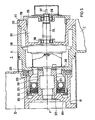
- FIG. 3 shows a section through the joint 1 with base 9.
- the electric drive motor 101 arranged in the interior of the base, including the reduction gear 102, is screwed to the base by means of screw connections 110.
- a displacement sensor 113 indicated by dashed lines, can also be plugged onto the shaft end 112 of the motor 101.
- the drive motor 101 is a three-phase motor with permanent excitation and a relatively low moment of inertia.
- the output pinion 103 of the transmission 102 meshes with a gear 104.
- This gear wheel 104 is firmly connected to a coaxial mounting flange 106 via screw connections 107.
- the mounting flange 106 designed as a rotating part and the gear wheel 104 are guided axially and radially in the bearing housing 105, which forms part of the joint housing, specifically axially via the needle bearing 109 and axially and radially via a tapered roller bearing 108.
- the bearings 108 and 109 are under tension by a spring 114.
- the bearing 108 is preloaded directly by the spring 114 and the bearing 109 via the gear 104 and the mounting flange 106. Since the mounting flange 106 is guided firmly on the bearing housing on a needle bearing ring of almost joint diameter, extensive clearance can be achieved in connection with the tapered roller bearing.
- the mounting flange 106 of the joint 1 can be screwed on its shoulder 115 to the joint 2 shown in FIG. 4, specifically to the tubular housing 211 of the joint 2.
- the electric drive motor 212 installed in the joint 2 drives a pinion 214 via a reduction gear 213, which meshes with a gear wheel 215.
- This gear wheel 215 is screwed to a coaxial flange 216.
- the annular shoulder 217 of this flange 216 is guided axially via a needle bearing 222 on a pressure ring 218 screwed to the joint housing.
- a ball bearing 219 which is prestressed by a spring 220 supported on the pressure ring 218, serves for the radial guidance of the flange 216.
- the bearing 222 is also preloaded via ring 221, gear wheel 215 and flange 216, so that a tight bearing is ensured.
- Figure 5 shows the joint 3 between the upper arm 7 and forearm 8 for rotation about the z-axis.
- the joint housing is essentially formed by two centrally adjacent tubular end parts 71 and 81 of the upper arm 7 and the forearm 8.
- the housing 310 of the electric drive motor 311 is pushed in up to the annular shoulder 312 and is screwed here to the part 71 via indicated screw connections 313.
- the shaft 314 of the motor 311 is guided in a ball bearing 316 arranged in the housing 310 and in a bearing cover 315.
- the shaft 314 is provided at one end 317 with receiving threads for displacement or speed sensors, not shown, and coaxially carries a reduction gear 318 (harmonic drive) at the other end.
- a cylindrical driver 319 coaxially encompassed by part 81 and lying in the longitudinal axis of the shaft, is screwed to reduction gear 318 and is guided in a coaxial support tube 320 fastened to part 71 by means of a ball bearing 321 located centrally to the forearm.
- the ball bearing 321 resting against a circumferential shoulder 323 of the driver 319 is under the pretension of a compression spring 324, which is supported on the pressure ring 325 screwed to the support tube 320.
- the end of the driver 319 is connected to the coupling part 811 of the end part 81 of the forearm 8 via indicated screw connections 336.
- the forearm 8 is also guided through an axial bearing 326, which is arranged between the adjoining annular surfaces of the parts 71 and 81 and is likewise under the compensating prestress of the spring 324.
- the forearm 8 can be released from the joint 3 after loosening the screw connections 322.
- Motor 312, gear 318 and driver 319 can be pulled out of part 71 after loosening the screw connections 313 indicated by dashed lines.
- Figure 6 shows the three interconnected joints 4 to 6 between the front arm 8 and gripper 10, with which rotations about the axes u, v and w are possible.
- the joint 4 consists of a tubular inner part 410 which can be screwed to the forearm 8 via a flange 411.
- the inner part 410 (rotating part) simultaneously forms the housing of the electric drive motor 412.
- This is a three-phase motor with permanent excitation and low moment of inertia and is initially arranged in the joint 3, so that its masses come into play as little as possible with regard to bending stress.
- the shaft 413 of the motor 412 drives a reduction gear 414 (harmonic drive) which is connected coaxially to the motor and whose inner part is screwed to the flange 415 of the tubular outer part 416 (rotating part) coaxially surrounding the inner part 410.
- the outer part 416 is guided on the inner part 410 via two spaced ball bearings 417 and 418. The distance between the two ball bearings 417 and 418 is selected so that the highest possible moments can be easily absorbed.
- the outer part 416 has an attached support part 420 in which the joint 5 is seated.
- the joint 5 also consists of a tubular inner part 510 screwed to the side support part 420, which at the same time forms the housing of the electric drive motor 511 and a tubular outer part 512 coaxially surrounding the inner part 510 with a vertically attached, also tubular add-on support part 513.
- the motor shaft 514 is coupled to the outer part 512 via the built-on reduction gear 515 and a bearing cover 516 connected to it on the output side.
- Inner part 510 and outer part 512 are again supported against one another via ball bearings 517 and 518. After loosening the indicated screw connections 519, the joint 5 can be pulled out of the joint 4 will.
- the inner part 510 together with the motor and transmission can be pulled out of the outer part 512.
- the joint 6 consists of the tubular inner part 610 which can be screwed to the mounting support part 513 of the joint and which likewise simultaneously forms the housing of the electric drive motor 611, and of a tubular outer part 612 which coaxially surrounds this inner part and which is held on the inner part via ball bearings 613 and 614 which are kept at a distance is supported.
- the drive connection between the motor shaft 615 and the outer part 612 runs via the coaxially mounted reduction gear 616, with the driven part of which the coupling flange 617 of the outer part 612 is screwed. After loosening the screw connections 618, the inner part 610 with motor and gear can be pulled out of the outer part 612.
- a displacement sensor 619 is arranged here, as with all other joints, on the side of the motor shaft 615 facing away from the transmission.
- the construction described above is characterized by a space-saving structure, ease of maintenance and high positioning accuracy.
Landscapes
- Engineering & Computer Science (AREA)
- Robotics (AREA)
- Mechanical Engineering (AREA)
- Manipulator (AREA)
Description
- Die Erfindung bezieht sich auf ein Robotergelenk mit im Gehäuse eingebautem elektrischen Antriebsmotor und Untersetzungsgetriebe, bei dem
- a) das abtreibende Ritzel des Untersetzungsgetriebes in ein Zahnrad eingreift, mit dem koaxial ein Anbauflansch verbunden ist;
- b) der Anbauflansch für ein nachfolgendes Bauteil des Roboters durch Lager in einem Gehäuse geführt ist.
- Eine solche Konstruktion ist im Prinzip aus der FR-A-2 315 629 bekannt.
- Bei dieser Lösung ist in einem zylindrischen Gehäuse koaxial ein Untersetzungsgetriebe (Harmonic Drive) doppelt gelagert. Das Spiel der hierbei verwendeten Kugellager ist über Schrauben einstellbar. Das Getriebe wird über ein Eingangszahnrad von einem angebauten Motor angetrieben.
- Zur Spielverminderung bei Lagern ist es auch bekannt, die Lager mittels Federn vorzuspannen (vergl. z.D. DE-A1-1 931 817).
- Hinsichtlich weiterer Ausführungsformen von Gelenkrobotern und Gelenkkonstruktionen wird z.B. auf die DE-AS 25 26 504, DE-AS 11 48 721 und die europäischen Patentanmeldungen 22 332 und 48 905 verwiesen.
- Industrieroboter sollen folgenden Anforderungen genügen:
- Sie sollten mudular als Baukastensystem aufbaubar sein, relativ wenig Platz benötigen, montage- und wartungsfreundlich sein und gleichzeitig eine hohe Verfahrgeschwindigkeit mit hoher Positioniergenauigkeit vereinen.
- Eine hohe Wiederholbarkeit der Positionierungsvorgänge bei einem modularen System erfordert dabei, daß die einzelnen Gelenke, vor allem am Beginn des Roboterarms, möglichst spielfrei sind. Diese Forderung läßt sich im allgemeinen nicht ohne weiteres mit einem platzsparenden Aufbau des Gelenks vereinen.
- Die Aufgabe der vorliegenden Erfindung besteht darin, unter Zuhilfenahme handelsüblicher Maschinenteile ein möglichst spielfreies und kompakt bauendes Robotergelenk im Rahmen eines modularen Baukastensystems zu schaffen.
- Diese Aufgabe wird erfindungsgemäß durch folgende Merkmale gelöst:
- c) zwischen Anbauflansch und Gehäuseteil ist ein unter Federspannung stehendes Kegelrollenlager angeordnet und
- d) zwischen Gehäuseteil und einer Ringschulter des Anbauflansches ist ein zusätzliches, ebenfalls unter Federvorspannung stehendes Axiallager vorgesehen, dessen Durchmesser nahezu dem Gelenkdurchmesser entspricht.
- Als Antriebsmotor wird ferner mit Vorteil ein permanenterregter Drehstrommotor benutzt, der auf der dem Getriebe abgewandten Seite gleichzeitig auch noch den Weggeber für die Lageregelung und Drehzahlführung trägt.
- Durch die vorstehend beschriebenen Merkmale erhält man ein Gelenk, das sich für den modularen Aufbau eines Roboters eignet und eine hohe Positioniergenauigkeit garantiert.
- Anhand eines in der Zeichnung dargestellten Ausführungsbeispiels sei die Erfindung näher beschrieben; es zeigen:
- Figur 1 eine Seitenansicht eines Industriegelenkroboters,
- Figur 2 eine Draufsicht auf den Roboter nach Figur 1,
- Figuren 3 und 4 Längsschnitte durch Gelenke zwischen Ständer und Oberarm,
- Figur 5 einen Schnitt durch das Gelenk zwischen Ober- und Vorderarm und
- Figur 6 einen Längsschnitt durch drei aneinandergesteckte Gelenke zwischen Unterarm und Greifer.
- Bei dem in Figur 1 und 2 schematisch dargestellten Industrie-Gelenkroboter sitzt auf einem Ständersockel 9 das Gelenk 1 (Rumpfgelenk), durch das eine Drehung um die x-Achse in einem Bereich von z.B. 400° möglich ist. Mit diesem Gelenk 1 ist ein Gelenk 2 (Schultergelenk) verschraubt, durch das eine Drehung um die senkrecht zur x-Achse liegende y-Achse in einem Bereich von z.B. 250° möglich ist.
- An diesem Gelenk 2 ist seitlich der Oberarm 7 befestigt. Dieser trägt am anderen Ende das Gelenk 3, durch das eine Drehung von z.B. 320° um die senkrecht zur Armlängsrichtung liegende z-Achse möglich ist. Die z-Achse und y-Achse liegen dabei parallel zueinander.
- Am Gelenk 3 ist der parallel zum Oberarm 7 geführte Vorderarm 8 befestigt. An diesen Vorderarm schließen sich drei Gelenke 4, 5 und 6 an, die zur Drehung um 300°, 180° und 540° in den Drehachsen u, v und w dienen.
- Am Gelenk 6 ist der eigentliche Greifer 10 (Hand) befestigbar.
- Wie ersichtlich, liegen jeweils die Achsen x, u und w in der gleichen Ebene, während die Achsen y und z parallel zueinander sind.
- Figur 3 zeigt einen Schnitt durch das Gelenk 1 mit Sockel 9. Wie ersichtlich, ist der im Sockelinnern angeordnete elektrische Antriebsmotor 101 samt Untersetzungsgetriebe 102 mittels Schraubverbindungen 110 mit dem Sockel verschraubt. Auf das Wellenende 112 des Motors 101 ist noch ein gestrichelt angedeuteter Weggeber 113 aufsteckbar. Der Antriebsmotor 101 ist ein Drehstrommotor mit Permanenterregung und relativ niedrigem Trägheitsmoment.
- Das Abtriebsritzel 103 des Getriebes 102 greift in ein Zahnrad 104 ein. Dieses Zahnrad 104 ist über Schraubverbindungen 107 mit einem koaxialen Anbauflansch 106 fest verbunden. Der als Drehteil ausgebildete Anbauflansch 106 und das Zahnrad 104 sind im Lagergehäuse 105, das einen Teil des Gelenkgehäuses bildet, axial und radial geführt, und zwar axial über das Nadellager 109 und axial und radial über ein Kegelrollenlager 108. Die Lager 108 und 109 stehen dabei durch eine Feder 114 unter Vorspannung. Das Lager 108 wird unmittelbar durch die Feder 114 vorgespannt und das Lager 109 über Zahnrad 104 und Anbauflansch 106. Da der Anbauflansch 106 fest am Lagergehäuse auf einem Nadellagerkranz von nahezu Gelenkdurchmesser geführt ist, läßt sich in Verbindung mit dem Kegelrollenlager eine weitgehende Spielfreiheit erreichen.
- Nach Lösen der Schraubverbindungen 11 können das Lagergehäuse 105 und die mit ihm verbundenen Teile vom Ständersockel 9 abgehoben werden.
- Der Anbauflansch 106 des Gelenkes 1 ist an seiner Schulter 115 mit dem in Figur 4 gezeigten Gelenk 2 verschraubbar, und zwar mit dem rohrförmigen Gehäuse 211 des Gelenks 2.
- Der im Gelenk 2 eingebaute elektrische Antriebsmotor 212 treibt über ein Untersetzungsgetriebe 213 ein Ritzel 214, das in ein Zahnrad 215 eingreift. Dieses Zahnrad 215 ist mit einem koaxialen Flansch 216 verschraubt. Die Ringschulter 217 dieses Flansches 216 ist über ein Nadellager 222 auf einem mit dem Gelenkgehäuse verschraubten Druckring 218 axial geführt. Zur radialen Führung des Flansches 216 dient ein Kugellager 219, das durch eine sich am Druckring 218 abstützende Feder 220 vorgespannt ist. Gleichzeitig steht hierdurch über Ring 221, Zahnrad 215 und Flansch 216 auch das Lager 222 unter Vorspannung, so daß eine straffe Lagerung gesichert ist.
- Figur 5 zeigt das Gelenk 3 zwischen Oberarm 7 und Vorderarm 8 zur Drehung um die z-Achse. Das Gelenkgehäuse wird im wesentlichen durch zwei zentrisch aneinandergrenzende rohrförmige Endteile 71 und 81 des Oberarmes 7 und des Vorderarmes 8 gebildet.
- Im Endteil 71 ist das Gehäuse 310 des elektrischen Antriebsmotors 311 bis zur Ringschulter 312 eingeschoben und hier über angedeutete Schraubverbindungen 313 mit dem Teil 71 verschraubt.
- Die Welle 314 des Motors 311 ist in einem im Gehäuse 310 und einem im Lagerdeckel 315 angeordneten Kugellager 316 geführt. Die Welle 314 ist an einem Ende 317 mit Aufnahmegewinden für nicht dargestellte Weg- bzw. Drehzahlgeber versehen und trägt am anderen Ende koaxial ein Untersetzungsgetriebe 318 (Harmonic Drive). An das Untersetzungsgetriebe 318 ist ein vom Teil 81 koaxial umfaßter,in der Wellenlängsachse liegender zylindrischer Mitnehmer 319 angeschraubt, der in einem am Teil 71 befestigten koaxialen Tragrohr 320 mittels eines mittig zum Vorderarm liegenden Kugellagers 321 geführt ist. Das an einer umlaufenden Schulter 323 des Mitnehmers 319 anliegende Kugellager 321 steht dabei unter der Vorspannung einer Druckfeder 324, die sich an dem mit dem Tragrohr 320 verschraubten Druckring 325 abstützt.
- Das Ende des Mitnehmers 319 ist mit dem Kupplungsteil 811 des Endteils 81 des Vorderarms 8 über angedeutete Schraubverbindungen 336 verbunden.
- Zusätzlich ist der Vorderarm 8 noch durch ein Axiallager 326 geführt, das zwischen den aneinandergrenzenden Ringflächen der Teile 71 und 81 angeordnet ist und ebenfalls unter der kompensierenden Vorspannung der Feder 324 steht.
- Der Vorderarm 8 kann nach Lösen der Schraubverbindungen 322 vom Gelenk 3 gelöst werden.
- Motor 312, Getriebe 318 und Mitnehmer 319 können nach Lösen der gestrichelt angedeuteten Schraubverbindungen 313 aus dem Teil 71 herausgezogen werden.
- Figur 6 zeigt die drei aneinandergesteckten Gelenke 4 bis 6 zwischen Vorderarm 8 und Greifer 10, mit denen Drehungen um die Achsen u, v und w möglich sind.
- Wie ersichtlich, besteht das Gelenk 4 aus einem rohrförmigen Innenteil 410, das über einen Flansch 411 mit dem Vorderarm 8 verschraubbar ist. Das Innenteil 410 (Drehteil) bildet gleichzeitig das Gehäuse des elektrischen Antriebsmotors 412. Dieser ist ein Drehstrommotor mit Permanenterregung und niedrigem Trägheitsmoment und ist zunächst dem Gelenk 3 angeordnet, so daß seine Massen hinsichtlich einer Biegebeanspruchung möglichst wenig zur Geltung kommen.
- Die Welle 413 des Motors 412 treibt ein koaxial an den Motor anschließendes, am Innenteil befestigtes Untersetzungsgetriebe 414 (Harmonic Drive), dessen abtreibender Teil mit dem Flansch 415 des rohrförmigen, das Innenteil 410 koaxial umgebenden rohrförmigen Außenteils 416 (Drehteil) verschraubt ist. Das Außenteil 416 ist dabei über zwei auf Abstand gehaltende Kugellager 417 und 418 am Innenteil 410 geführt. Der Abstand der beiden Kugellager 417 und 418 ist so gewählt, daß möglichst hohe Momente gut aufgenommen werden können.
- Nach Lösen der angedeuteten Schraubverbindungen 419 und 421 kann das Innenteil samt Motor 412 und Getriebe 414 aus dem Außenteil 416 herausgezogen werden.
- Der Außenteil 416 hat ein angesetztes Tragteil 420, in dem das Gelenk 5 sitzt.
- Das Gelenk 5 besteht ebenfalls aus einem rohrförmigen, mit dem seitlichen Tragteil 420 verschraubten Innenteil 510, das gleichzeitig das Gehäuse des elektrischen Antriebsmotors 511 bildet und einen das Innenteil 510 koaxial umgebenden rohrförmigen Außenteil 512 mit einem senkrecht angesetzten, ebenfalls rohrförmigen Anbauträgerteil 513. Die Motorwelle 514 ist über das angebaute Untersetzungsgetriebe 515 und einen damit abtriebsseitig verbundenen Lagerdeckel 516 mit dem Äußenteil 512 gekuppelt.
- Innenteil 510 und Außenteil 512 sind ebenfalls wieder über Kugellager 517 und 518 gegeneinander abgestützt. Nach Lösen der angedeuteten Schraubverbindungen 519 kann das Gelenk 5 aus dem Gelenk 4 herausgezogen werden.
- Nach Lösen der Schraubverbindungen 520 und 521 kann das Innenteil 510 samt Motor und Getriebe aus dem Außenteil 512 herausgezogen werden.
- Das Gelenk 6 besteht aus dem mit dem Anbauträgerteil 513 des Gelenkes verschraubbaren rohrförmigen Innenteil 610, das ebenfalls gleichzeitig das Gehäuse des elektrischen Antriebsmotors 611 bildet, und aus einem dieses Innenteil koaxial umgebenden rohrförmigen Außenteil 612, das über auf Abstand gehaltene Kugellager 613 und 614 am Innenteil abgestützt ist. Die Antriebsverbindung zwischen Motorwelle 615 und Außenteil 612 läuft über das koaxial angebaute Untersetzungsgetriebe 616, mit dessen abtreibenden Teil der Kupplungsflansch 617 des Außenteils 612 verschraubt ist. Nach Lösen der Schraubverbindungen 618 kann das Innenteil 610 mit Motor und Getriebe aus dem Außenteil 612 herausgezogen werden.
- Wie gestrichelt angedeutet, ist hierbei, wie auch bei allen anderen Gelenken, auf der dem Getriebe abgewandten Seite der Motorwelle 615 ein Weggeber 619 angeordnet.
- Die vorstehend beschriebene Konstruktion zeichnet sich durch einen platzsparenden Aufbau, hohe Wartungsfreundlichkeit und hohe Positioniergenauigkeit aus.
Claims (3)
gekennzeichnet durch folgende Merkmale:
Priority Applications (1)
| Application Number | Priority Date | Filing Date | Title |
|---|---|---|---|
| AT84103246T ATE28818T1 (de) | 1983-04-06 | 1984-03-23 | Robotergelenk. |
Applications Claiming Priority (3)
| Application Number | Priority Date | Filing Date | Title |
|---|---|---|---|
| DE8310054U DE8310054U1 (de) | 1983-04-06 | 1983-04-06 | Robotergelenk |
| DE19833312377 DE3312377A1 (de) | 1983-04-06 | 1983-04-06 | Robotergelenk |
| DE3312377 | 1983-04-06 |
Publications (2)
| Publication Number | Publication Date |
|---|---|
| EP0121844A1 EP0121844A1 (de) | 1984-10-17 |
| EP0121844B1 true EP0121844B1 (de) | 1987-08-12 |
Family
ID=25809750
Family Applications (1)
| Application Number | Title | Priority Date | Filing Date |
|---|---|---|---|
| EP84103246A Expired EP0121844B1 (de) | 1983-04-06 | 1984-03-23 | Robotergelenk |
Country Status (3)
| Country | Link |
|---|---|
| US (1) | US4738576A (de) |
| EP (1) | EP0121844B1 (de) |
| DE (2) | DE3312377A1 (de) |
Families Citing this family (29)
| Publication number | Priority date | Publication date | Assignee | Title |
|---|---|---|---|---|
| JPS60161083A (ja) * | 1984-01-30 | 1985-08-22 | 三菱電機株式会社 | ア−ク溶接ロボツトの旋回軸バツクラツシユ補正装置 |
| DE3627745A1 (de) * | 1985-08-20 | 1987-03-05 | Tokico Ltd | Industriewiedergaberoboter |
| SE462323B (sv) * | 1987-04-29 | 1990-06-11 | Asea Ab | Industrirobot med glappfri lagring av stativet i bottenplattan medelst axelkoppling |
| US4951517A (en) * | 1987-10-28 | 1990-08-28 | Canon Kabushiki Kaisha | Rotational driving apparatus with frictional engagement and robot using the same |
| JP2525462B2 (ja) * | 1988-06-23 | 1996-08-21 | ファナック株式会社 | 産業用ロボットの軸支持体構造 |
| JPH0261588U (de) * | 1988-10-24 | 1990-05-08 | ||
| US5102377A (en) * | 1991-04-08 | 1992-04-07 | Stanley Spanski | Rotary actuator with epicyclic transmission |
| US5293107A (en) * | 1993-02-24 | 1994-03-08 | Fanuc Robotics North America, Inc. | Motorized rotary joint and method of constructing a modular robot utilizing same |
| USD351849S (en) | 1993-07-09 | 1994-10-25 | Barrett Technology, Inc. | Robotic shoulder |
| IT1272083B (it) * | 1993-12-17 | 1997-06-11 | Comau Spa | Robot industriale con gruppi riduttori integrati. |
| US5523662A (en) * | 1994-05-02 | 1996-06-04 | Engineering Services, Inc. | Modular, expandable and reconfigurable robot |
| JPH0957680A (ja) * | 1995-08-18 | 1997-03-04 | Tokico Ltd | 工業用ロボット |
| JP4755357B2 (ja) * | 2001-04-18 | 2011-08-24 | ナブテスコ株式会社 | 減速機 |
| FR2845303B1 (fr) * | 2002-10-03 | 2005-07-08 | Forest Line Albert | Tete pivotante multiaxe de machine-outil |
| DE102006016404B3 (de) | 2006-04-07 | 2007-11-22 | Krauss-Maffei Wegmann Gmbh & Co. Kg | Schutzeinrichtung an einer Ein-/Ausstiegsluke eines Kampffahrzeugs, insbesondere eines Kampfpanzers |
| US8176808B2 (en) * | 2007-09-13 | 2012-05-15 | Foster-Miller, Inc. | Robot arm assembly |
| CA2709273C (en) | 2007-12-14 | 2013-01-15 | Foster-Miller, Inc. | Modular mobile robot |
| US8414043B2 (en) * | 2008-10-21 | 2013-04-09 | Foster-Miller, Inc. | End effector for mobile remotely controlled robot |
| US20100101356A1 (en) * | 2008-10-24 | 2010-04-29 | Albin Scott R | Remotely controlled mobile robot in-line robot arm and end effector mechanism |
| US8322249B2 (en) * | 2008-12-18 | 2012-12-04 | Foster-Miller, Inc. | Robot arm assembly |
| US8141924B2 (en) * | 2008-12-29 | 2012-03-27 | Foster-Miller, Inc. | Gripper system |
| TWI415724B (zh) * | 2010-12-22 | 2013-11-21 | Ind Tech Res Inst | 並聯機器人及手腕模組 |
| CN102161206B (zh) * | 2010-12-29 | 2013-03-06 | 奇瑞汽车股份有限公司 | 一种机器人平衡器联接结构及其装配方法 |
| CN103612265A (zh) * | 2013-11-26 | 2014-03-05 | 苏州晓炎自动化设备有限公司 | 一种机器人肘关节体前端转动机构 |
| TWI680040B (zh) * | 2014-09-17 | 2019-12-21 | 美商法伯沃克斯分解股份有限公司 | 利於轂部移除的多組件機器人轂部安裝盤 |
| CN104708618A (zh) * | 2015-03-16 | 2015-06-17 | 广东顺德三合工业自动化设备有限公司 | 机器人 |
| CN105522567A (zh) * | 2016-01-30 | 2016-04-27 | 东莞市腾迈五金塑胶制品有限公司 | 一种多功能六轴机械手 |
| CN105619402B (zh) * | 2016-03-17 | 2017-12-12 | 昆山华恒机器人有限公司 | 关节型工业机器人 |
| JP7440240B2 (ja) * | 2019-10-23 | 2024-02-28 | ファナック株式会社 | ロボット |
Family Cites Families (19)
| Publication number | Priority date | Publication date | Assignee | Title |
|---|---|---|---|---|
| US2594578A (en) * | 1948-03-23 | 1952-04-29 | Timken Roller Bearing Co | Tapered roller bearing |
| DE1041307B (de) * | 1956-01-13 | 1958-10-16 | Skf Kugellagerfabriken Gmbh | Drehkranz grosser Abmessungen |
| BE582789A (de) * | 1958-09-19 | |||
| DE1577411A1 (de) * | 1966-03-08 | 1970-02-19 | Georg Mueller Kg Kugellagerfab | Lagerung und Antrieb von Rundtischen an Werkzeugmaschinen,insbesondere an Flachschleifmaschinen |
| DE1903882B2 (de) * | 1969-01-27 | 1973-03-08 | Werkzeugmaschinen Fabrik Gildemeister & Co AG, 4800 Bielefeld | Mehrspindel-drehautomat mit drehschaltbarer spindeltrommel und hydrodynamisch arbeitenden drehspindellagern |
| US3893573A (en) * | 1973-08-20 | 1975-07-08 | Nasa | Variable ratio mixed-mode bilateral master-slave control system for shuttle remote manipulator system |
| US4046262A (en) * | 1974-01-24 | 1977-09-06 | The United States Of America As Represented By The Administrator Of The National Aeronautics And Space Administration | Anthropomorphic master/slave manipulator system |
| US3920972A (en) * | 1974-07-16 | 1975-11-18 | Cincinnati Milacron Inc | Method and apparatus for programming a computer operated robot arm |
| DE2530261C2 (de) * | 1974-10-22 | 1986-10-23 | Asea S.p.A., Mailand/Milano | Programmiereinrichtung für einen Manipulator |
| IT1027240B (it) * | 1975-01-03 | 1978-11-20 | Oboni G | Manipolatore con elementi compo nibili realizzianti i diversi assi di spostamento |
| FR2314390A1 (fr) * | 1975-06-13 | 1977-01-07 | Sofermo | Articulation modulaire autonome pour mecanismes divers et en particulier pour robots |
| FR2315629A1 (fr) * | 1975-06-24 | 1977-01-21 | Sofermo | Pivot modulaire autonome pour mecanismes divers en particulier pour robot |
| CA1034393A (en) * | 1976-10-13 | 1978-07-11 | Spar Aerospace Products Limited | Powered wrist joint |
| GB1592491A (en) * | 1977-02-17 | 1981-07-08 | British Aerospace | Bearing assemblies |
| SE410758B (sv) * | 1979-01-18 | 1979-10-29 | Skf Ab | Anordning for lagring av ett element virdbart kring en huvudsakligen vertikal axel |
| JPS5950474B2 (ja) * | 1979-06-30 | 1984-12-08 | ファナック株式会社 | 産業用ロボツト |
| JPS6039518B2 (ja) * | 1980-09-30 | 1985-09-06 | ファナック株式会社 | 工業用ロボットの手首機構 |
| US4392776A (en) * | 1981-05-15 | 1983-07-12 | Westinghouse Electric Corp. | Robotic manipulator structure |
| FR2512727A1 (fr) * | 1981-09-15 | 1983-03-18 | Renault | Poignet orientable a trois axes de rotation pour robot industriel |
-
1983
- 1983-04-06 DE DE19833312377 patent/DE3312377A1/de not_active Withdrawn
- 1983-04-06 DE DE8310054U patent/DE8310054U1/de not_active Expired
-
1984
- 1984-03-23 EP EP84103246A patent/EP0121844B1/de not_active Expired
-
1986
- 1986-04-03 US US06/848,336 patent/US4738576A/en not_active Expired - Fee Related
Also Published As
| Publication number | Publication date |
|---|---|
| DE3312377A1 (de) | 1984-10-18 |
| EP0121844A1 (de) | 1984-10-17 |
| US4738576A (en) | 1988-04-19 |
| DE8310054U1 (de) | 1986-02-27 |
Similar Documents
| Publication | Publication Date | Title |
|---|---|---|
| EP0121843B1 (de) | Robotergelenk | |
| EP0121844A1 (de) | Robotergelenk | |
| DE3048067C2 (de) | Getriebeanordnung für den Gelenkkopf eines Manipulators | |
| EP0178620B1 (de) | Robotergelenkanordnung | |
| DE102010007631B4 (de) | Parallelroboter mit einem Handgelenkabschnitt mit drei Freiheitsgraden | |
| DE69112557T2 (de) | Roboterhandgelenk. | |
| DE102016004787B4 (de) | Antriebsvorrichtung für einen Roboter und Verfahren zu ihrer Herstellung | |
| DE102017217907B4 (de) | Roboterarm mit einer Roboterhand-Antriebsvorrichtung | |
| EP0207150B1 (de) | Industrie-roboter für unterschiedliche einsatzzwecke | |
| DE2619336B2 (de) | Gelenkkopf für einen Manipulator zur Befestigung an einem Manipulatorann | |
| EP2666600A2 (de) | Industrieroboter mit in einem Handgrundgehäuse sich erstreckenden Antrieben | |
| DE102006011823A1 (de) | Positioniereinrichtung | |
| DE102013216449A1 (de) | Industrieroboter mit wenigstens einem Antrieb | |
| EP0133499A2 (de) | Getriebekopf für Manipulatoren | |
| DE7619985U1 (de) | Selbstaendiger modularer drehzapfen zum verbinden zweier maschinenelemente | |
| DE3490498T1 (de) | Handgelenk für Industrieroboter | |
| EP0674122A2 (de) | Getriebemotor | |
| DE3113184C2 (de) | ||
| DE3428748C2 (de) | Getriebekopf für Manipulatoren | |
| DE3719064A1 (de) | Roboterhandgelenk | |
| EP0527121A1 (de) | Getriebe zum Antrieb eines Gelenkes insbesondere eines Industrieroboters | |
| DE3788234T2 (de) | Manipulator mit Stangenmechanismus. | |
| DE3704951C2 (de) | ||
| DE3530365A1 (de) | Handgelenk fuer industrieroboter | |
| DE3809751A1 (de) | Futterkopf fuer automatische werkzeugmaschinen |
Legal Events
| Date | Code | Title | Description |
|---|---|---|---|
| PUAI | Public reference made under article 153(3) epc to a published international application that has entered the european phase |
Free format text: ORIGINAL CODE: 0009012 |
|
| AK | Designated contracting states |
Designated state(s): AT BE CH DE FR GB IT LI SE |
|
| 17P | Request for examination filed |
Effective date: 19841128 |
|
| RAP1 | Party data changed (applicant data changed or rights of an application transferred) |
Owner name: MANUTEC GESELLSCHAFT FUER AUTOMATISIERUNGS- UND HA |
|
| 17Q | First examination report despatched |
Effective date: 19860320 |
|
| R17C | First examination report despatched (corrected) |
Effective date: 19860908 |
|
| GRAA | (expected) grant |
Free format text: ORIGINAL CODE: 0009210 |
|
| AK | Designated contracting states |
Kind code of ref document: B1 Designated state(s): AT BE CH DE FR GB IT LI SE |
|
| REF | Corresponds to: |
Ref document number: 28818 Country of ref document: AT Date of ref document: 19870815 Kind code of ref document: T |
|
| REF | Corresponds to: |
Ref document number: 3465265 Country of ref document: DE Date of ref document: 19870917 |
|
| ET | Fr: translation filed | ||
| ITF | It: translation for a ep patent filed | ||
| PLBE | No opposition filed within time limit |
Free format text: ORIGINAL CODE: 0009261 |
|
| STAA | Information on the status of an ep patent application or granted ep patent |
Free format text: STATUS: NO OPPOSITION FILED WITHIN TIME LIMIT |
|
| 26N | No opposition filed | ||
| ITTA | It: last paid annual fee | ||
| PGFP | Annual fee paid to national office [announced via postgrant information from national office to epo] |
Ref country code: AT Payment date: 19930224 Year of fee payment: 10 |
|
| PGFP | Annual fee paid to national office [announced via postgrant information from national office to epo] |
Ref country code: DE Payment date: 19930518 Year of fee payment: 10 |
|
| PGFP | Annual fee paid to national office [announced via postgrant information from national office to epo] |
Ref country code: CH Payment date: 19930621 Year of fee payment: 10 |
|
| PGFP | Annual fee paid to national office [announced via postgrant information from national office to epo] |
Ref country code: GB Payment date: 19940218 Year of fee payment: 11 |
|
| PGFP | Annual fee paid to national office [announced via postgrant information from national office to epo] |
Ref country code: BE Payment date: 19940308 Year of fee payment: 11 |
|
| PGFP | Annual fee paid to national office [announced via postgrant information from national office to epo] |
Ref country code: FR Payment date: 19940317 Year of fee payment: 11 |
|
| PG25 | Lapsed in a contracting state [announced via postgrant information from national office to epo] |
Ref country code: AT Effective date: 19940323 |
|
| PGFP | Annual fee paid to national office [announced via postgrant information from national office to epo] |
Ref country code: SE Payment date: 19940324 Year of fee payment: 11 |
|
| PG25 | Lapsed in a contracting state [announced via postgrant information from national office to epo] |
Ref country code: LI Effective date: 19940331 Ref country code: CH Effective date: 19940331 |
|
| REG | Reference to a national code |
Ref country code: CH Ref legal event code: PL |
|
| PG25 | Lapsed in a contracting state [announced via postgrant information from national office to epo] |
Ref country code: DE Effective date: 19941201 |
|
| EAL | Se: european patent in force in sweden |
Ref document number: 84103246.9 |
|
| PG25 | Lapsed in a contracting state [announced via postgrant information from national office to epo] |
Ref country code: GB Effective date: 19950323 |
|
| PG25 | Lapsed in a contracting state [announced via postgrant information from national office to epo] |
Ref country code: SE Effective date: 19950324 |
|
| PG25 | Lapsed in a contracting state [announced via postgrant information from national office to epo] |
Ref country code: BE Effective date: 19950331 |
|
| BERE | Be: lapsed |
Owner name: MANUTEC G- FUR AUTOMATISIERUNGS- UND HANDHABUNGSS Effective date: 19950331 |
|
| GBPC | Gb: european patent ceased through non-payment of renewal fee |
Effective date: 19950323 |
|
| PG25 | Lapsed in a contracting state [announced via postgrant information from national office to epo] |
Ref country code: FR Free format text: LAPSE BECAUSE OF NON-PAYMENT OF DUE FEES Effective date: 19951130 |
|
| EUG | Se: european patent has lapsed |
Ref document number: 84103246.9 |
|
| REG | Reference to a national code |
Ref country code: FR Ref legal event code: ST |