EP0121131B1 - Handbetätigter Rohrabschneider - Google Patents
Handbetätigter Rohrabschneider Download PDFInfo
- Publication number
- EP0121131B1 EP0121131B1 EP84102349A EP84102349A EP0121131B1 EP 0121131 B1 EP0121131 B1 EP 0121131B1 EP 84102349 A EP84102349 A EP 84102349A EP 84102349 A EP84102349 A EP 84102349A EP 0121131 B1 EP0121131 B1 EP 0121131B1
- Authority
- EP
- European Patent Office
- Prior art keywords
- cutting head
- pipe
- gears
- pair
- operatively
- Prior art date
- Legal status (The legal status is an assumption and is not a legal conclusion. Google has not performed a legal analysis and makes no representation as to the accuracy of the status listed.)
- Expired
Links
- 238000005520 cutting process Methods 0.000 claims abstract description 63
- 238000006073 displacement reaction Methods 0.000 claims description 5
- 230000000306 recurrent effect Effects 0.000 claims 2
- 230000001351 cycling effect Effects 0.000 claims 1
- 238000010276 construction Methods 0.000 description 3
Images


Classifications
-
- B—PERFORMING OPERATIONS; TRANSPORTING
- B23—MACHINE TOOLS; METAL-WORKING NOT OTHERWISE PROVIDED FOR
- B23D—PLANING; SLOTTING; SHEARING; BROACHING; SAWING; FILING; SCRAPING; LIKE OPERATIONS FOR WORKING METAL BY REMOVING MATERIAL, NOT OTHERWISE PROVIDED FOR
- B23D21/00—Machines or devices for shearing or cutting tubes
- B23D21/06—Hand-operated tube-cutters
- B23D21/08—Hand-operated tube-cutters with cutting wheels
Definitions
- This invention relates to a pipe cutter of the hand tool type.
- a pipe cutter of this type and as defined in the pre-characterizing part of the following claim 1, is described in US-A-4 305 205.
- the cutter advancing apparatus is operated by hand from the side near the opening of the C-shaped housing, and pivotable around an axis which extends substantially in a plane vertical to the pipe axis. It is therefore not easily accessible when the pipe cutter is used in a restricted space, for instance when cutting a pipe fixed near a wall.
- a manual pipe cutter of somewhat similar construction is also described in US-A-4 177 557 of the applicant.
- the rotatable cutting head was made in one piece and, consequently, the various parts of the pipe cutter were difficult to assemble and to disassemble.
- the cutting disc was mounted for rotation about a fixed axis relative to the cutting head and, therefore, was difficult of access for removal and sharpening.
- This known cutter further includes a screw-and-knob arrangement to press a cutting disc against the pipe to be cut. This screw-and-knob arrangement protrudes from the cutting head, so that the pipe cannot be cut when it is very close to an obstruction.
- the manual pipe cutter of the invention is of relative simple construction. It is easier to assemble and disassemble and the cutting disc can be easily removed for sharpening or replacement. Moreover, the cutter advancing apparatus occupies much less room than in known manual pipe cutters, and is adapted for convenient operation, so that a pipe may be cut even when very close to an obstruction.
- the illustrated manual pipe cutter of Figures. 1 to 17 comprises a body 10, made of two halves 11 and 12 cooperatively forming a cutting head portion at 13 and a handle portion at 14.
- the cutting head portion 13 defines a pipe passage extending transversely through it and has a cutout at 15 forming an open mouth communicating transversely with the pipe passage to allow relative transverse displacement of a pipe inward into the pipe passage in the cutting head portion.
- a cutting head 16 made of two half-parts secured together by bolts, is rotatably mounted in the cutting head portion between the corresponding cutting head portions of the spaced-apart halves 11 and 12 of the body 10.
- the cutting edge portions of the two halves of the body define a pair of inner faces 17 and 18 which are mutually facing each other and engage the opposite sides respectively of the cutting head 16.
- the inner face 17 is formed with ratchet teeth 19 serially arranged circularly around the pipe passage. As shown in Figure 8, a bore extends transversely into the cutting head from the face adjacent the ratchet teeth 19.
- a pawl in the form of a pin 20, is slidable in that bore and is outwardly biased by a spring 21, such that its outer pointed end operatively abuts against the adjacent tooth 19.
- the ratchet teeth 19 and the pawl 20 are constructed and arranged such that, when the handle 14 is lowered in the direction of the arrow 22, as shown in Figure 16, the body 10 rotates the cutting head in the clockwise direction, as shown by the arrow 23.
- the handle 14 is pivoted in the direction of the arrow 24, as shown in Figure 14, the pawl 20 and ratchet teeth 19 allow the body 10 to idly pivot relative to the cutting head 16, such as when the latter bites a pipe 25.
- the reciprocative pivoting of the handle 14, as shown by the arrow 26, causes only unidirectional rotation of the cutting head 16 in the direction of the arrow 23, as shown in Figure 16.
- the cutting head 16, as the head portion 13, is provided with a pipe passage and a cutout forming an open mouth to insert the cutter endwise around the pipe 25 to be cut.
- a cutter-pressing jaw 27 is slidably mouted on the cutting head and is slidable in a predetermined direction transversely relative to the pipe passage and to the open mouth of the cutting head.
- a pair of guide rollers 28 are rotatively carried by the cutting head diametrically opposite to the cutter-pressing jaw 27 relative to the pipe passage. This allows operative displacement of the jaw toward the rollers to hold a pipe 25 between the rollers 28 and a cutting disc 29 carried by the jaw.
- the cutting disc 29 is arranged to engage the pipe 25 edgewise to cut it transversely.
- a blade spring 30 is fixed at one end to the cutting head and at its other end to the cutter-pressing jaw 27 and is made and arranged to retract the latter in opposite direction away from the rollers 28.
- a toothed rack 31 is fixed to the cutter-pressing jaw 27 and is bodily slidable endwise in the direction of the rollers 28.
- a pushbutton-and-gear arrangement is provided to progressively displace or slide the jaw 27 in the direction of the rollers 28 as the cutting operation progresses.
- the pushbutton-and-gear arrangement includes a pushbutton 32 and a ratchet-and-gear system operatively connecting the pushbutton 32 to the toothed rack and arranged for controlled operation of the same.
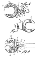
- the ratchet-and-gear system includes a first pair of gears 33 and 34 carried by the rotatable cutting head 16 and a second pair of gears 35 and 36 carried by the body 10 and displaceable with it translatively.
- the gears 33 and 34 are in meshing engagement one with the other and are translatively rotatable with the rotatable cutting head.
- the gear 33 is a double-toothed wheel or gear including one axial side 37 that drives the other axial side 38 bodily with it.
- the toothed wheel or gear forms a ratchet wheel 37 which meshes with the gear 34.
- a pin 39 is carried by the rotatable cutting head 16 and is spring biased into engagement as a pawl between a pair of teeth of the side 37 of the double gear. This forms a pawl-and- ratchet assembly to allow only unidirectional rotation of the gears.
- the side 38 of the double gear 33 has a couple of teeth removed, thus forming a non-toothed circumferential portion 40 that produces a detent to release the toothed rack 31 and allow the jaw to be retracted by the spring blade 30 away from the rollers 28 at the end of one cut through a pipe 25.
- the gears 34 and 35 form intermediate connection gears which mesh one with the other cyclically; that is, only when for each rotation of the cutting head 16, the latter has its mouth registering with the mouth of the head portion 13. Then gears 35 and 36 mesh one with the other.
- a gear sector 41 meshes with the intermediate connection gear 35 and is pivoted to produce a pivotable pawl to block the gears 35 and 36 against rotation in the direction opposite to the direction indicated by the arrow 42 in Figure 17 during a portion of the cycle of operation. This is done by abutment of the gear sector 41 with a pin 43.
- the pushbutton 32 includes a pushbutton head 44 which is secured at the outer end of an arm 45 that is pivoted at its other end around the axis of the gear 36.
- the pushbutton also includes a plunger 46 that is biased by a spring 47 toward pawl-like engagement with an adjacent tooth of the gear 36.
- a spring wire 48 engages the pivotable arm 45 to bias the same angularly away from engagement of the plunger 46 with a tooth of the gear 36.
- the plunger 46 is shaped to be wedged away from the gear 36 upon abutment with a blade 49.
- the up-and-down pivoting of the handle 14, as indicated by the arrow 26, causes rotation of the cutting head 16 and of the cutting disc 29 in the direction of the arrow 23 around the pipe to cut it; this is shown in Figure 15.
- Figure 16 shows the movements occurring upon release of the head 44 and by action of the spring wire 50 on the gear sector 41.
- the non-toothed portion 40 of the gear 33 registers with the toothed rack 31 and the jaw 27 is returned by the spring 30 to its starting position.
Landscapes
- Engineering & Computer Science (AREA)
- Mechanical Engineering (AREA)
- Shearing Machines (AREA)
- Surgical Instruments (AREA)
- Branch Pipes, Bends, And The Like (AREA)
- Scissors And Nippers (AREA)
Claims (9)
dadurch gekennzeichnet, daß
Priority Applications (1)
| Application Number | Priority Date | Filing Date | Title |
|---|---|---|---|
| AT84102349T ATE30219T1 (de) | 1983-03-07 | 1984-03-05 | Handbetaetigter rohrabschneider. |
Applications Claiming Priority (2)
| Application Number | Priority Date | Filing Date | Title |
|---|---|---|---|
| GB838306217A GB8306217D0 (en) | 1983-03-07 | 1983-03-07 | Tube/pipe cutter |
| GB8306217 | 1983-03-07 |
Publications (2)
| Publication Number | Publication Date |
|---|---|
| EP0121131A1 EP0121131A1 (de) | 1984-10-10 |
| EP0121131B1 true EP0121131B1 (de) | 1987-10-14 |
Family
ID=10539118
Family Applications (1)
| Application Number | Title | Priority Date | Filing Date |
|---|---|---|---|
| EP84102349A Expired EP0121131B1 (de) | 1983-03-07 | 1984-03-05 | Handbetätigter Rohrabschneider |
Country Status (4)
| Country | Link |
|---|---|
| EP (1) | EP0121131B1 (de) |
| AT (1) | ATE30219T1 (de) |
| DE (1) | DE3466766D1 (de) |
| GB (1) | GB8306217D0 (de) |
Cited By (2)
| Publication number | Priority date | Publication date | Assignee | Title |
|---|---|---|---|---|
| US9302402B2 (en) | 2007-03-15 | 2016-04-05 | Milwaukee Electric Tool Corporation | Pipe cutter |
| US12544842B2 (en) | 2020-10-30 | 2026-02-10 | Black & Decker Inc. | Power tool and power tool accessories for cutting tubular members |
Families Citing this family (6)
| Publication number | Priority date | Publication date | Assignee | Title |
|---|---|---|---|---|
| US6202307B1 (en) * | 1998-02-20 | 2001-03-20 | Leonard A. Wrate | Power-driven hand-held tubing cutter |
| TWM240019U (en) * | 2002-08-09 | 2004-08-01 | Tai-Hung Lee | Rotary tube-cutter |
| CN102133658B (zh) * | 2010-01-26 | 2013-03-27 | 泉峰(中国)贸易有限公司 | 切管机 |
| ES2454090B1 (es) * | 2012-10-09 | 2014-12-23 | Eduard Mondragón Condeminas | Dispositivo de corte simultáneo de dos elementos tubulares |
| CN109482978A (zh) * | 2018-12-24 | 2019-03-19 | 海盐沃企机电设备有限公司 | 一种棘轮式密封焊环切割器 |
| CN110977014A (zh) * | 2019-12-17 | 2020-04-10 | 爱牛管道工具(上海)有限公司 | 一种棘轮切割刀 |
Family Cites Families (7)
| Publication number | Priority date | Publication date | Assignee | Title |
|---|---|---|---|---|
| DE70989C (de) * | P. stoffels in Oberhausen, Rheinland | Rohrabschneider mit selbsttätigem Antrieb des Schneidrades | ||
| US2447371A (en) * | 1945-04-30 | 1948-08-17 | Sipsma Stewart | Single wheel ratchet pipe cutter |
| DE1452705A1 (de) * | 1964-03-20 | 1969-05-08 | Imp Eastman Corp | Vorrichtung zum Trennschneiden von Rohren |
| US3715804A (en) * | 1971-02-19 | 1973-02-13 | E Kelley | Free fulcrumed lever action for the cutting wheel pipe cutter |
| CA1079051A (en) * | 1977-01-17 | 1980-06-10 | Aurele Courty | Pipe cutter of the ratchet type |
| US4177557A (en) * | 1978-01-13 | 1979-12-11 | Aurele Courty | Tube cutter with a ratchet handle |
| US4305205A (en) * | 1980-04-09 | 1981-12-15 | The United States Of America As Represented By The Administrator Of The National Aeronautics And Space Administration | Open ended tubing cutters |
-
1983
- 1983-03-07 GB GB838306217A patent/GB8306217D0/en active Pending
-
1984
- 1984-03-05 AT AT84102349T patent/ATE30219T1/de not_active IP Right Cessation
- 1984-03-05 DE DE8484102349T patent/DE3466766D1/de not_active Expired
- 1984-03-05 EP EP84102349A patent/EP0121131B1/de not_active Expired
Cited By (3)
| Publication number | Priority date | Publication date | Assignee | Title |
|---|---|---|---|---|
| US9302402B2 (en) | 2007-03-15 | 2016-04-05 | Milwaukee Electric Tool Corporation | Pipe cutter |
| DE112008000686B4 (de) * | 2007-03-15 | 2016-07-28 | Milwaukee Electric Tool Corp. | Rohrschneider |
| US12544842B2 (en) | 2020-10-30 | 2026-02-10 | Black & Decker Inc. | Power tool and power tool accessories for cutting tubular members |
Also Published As
| Publication number | Publication date |
|---|---|
| EP0121131A1 (de) | 1984-10-10 |
| ATE30219T1 (de) | 1987-10-15 |
| DE3466766D1 (en) | 1987-11-19 |
| GB8306217D0 (en) | 1983-04-13 |
Similar Documents
| Publication | Publication Date | Title |
|---|---|---|
| US4438562A (en) | Manual pipe cutter | |
| US5009130A (en) | Coaxial cable stripper | |
| US4677748A (en) | Hand-operated cable cutter | |
| EP0121131B1 (de) | Handbetätigter Rohrabschneider | |
| EP0386950A1 (de) | Schrauber für Befestigungselemente | |
| DE10345765A1 (de) | Kreissäge | |
| US3118227A (en) | Tube cutting device | |
| AU780987B2 (en) | Hand-held can opener | |
| DE1253038B (de) | Photoapparat mit einer Filmtransporteinrichtung und einer Anschlussvorrichtung fuer eine Blitzlampeneinheit mit mehreren Blitzlampen | |
| US4063472A (en) | Remotely actuatable device for rotary knob | |
| US4449283A (en) | Semi-automatic insert tool | |
| DE2601037C3 (de) | Filterreinigungseinrichtung in einem Staubsauger | |
| DE3629920A1 (de) | Verschlussspannvorrichtung fuer kameras | |
| DE1597446C3 (de) | Photographische Kamera | |
| CN103128716B (zh) | 具有鼓状工具更换库的手持式工具机 | |
| CA1182284A (en) | Manual pipe cutter | |
| US4030592A (en) | Stencil cutting apparatus | |
| DE2040661C3 (de) | Steuermechanismus für Ab- und Aufblendung in einer Laufbildkamera | |
| EP0177363A2 (de) | Vorrichtung zum Entfernen von Innengraten | |
| DE2060363C3 (de) | Vorrichtung zur Uberblendungsaufnahme In einer Filmlauf kamera | |
| DE258787C (de) | ||
| DE958982C (de) | Fotografische Kamera mit Kupplung zwischen Filmfortschaltung und Verschlussaufzug | |
| DE2128481C3 (de) | Bildzählwerk | |
| DE1622232C (de) | Überblendeinrichtung fur Laufbild kameras | |
| DE2058570C3 (de) | Überblendvorrichtung in einer Laufbildkamera |
Legal Events
| Date | Code | Title | Description |
|---|---|---|---|
| PUAI | Public reference made under article 153(3) epc to a published international application that has entered the european phase |
Free format text: ORIGINAL CODE: 0009012 |
|
| AK | Designated contracting states |
Designated state(s): AT BE CH DE FR GB IT LI LU NL SE |
|
| 17P | Request for examination filed |
Effective date: 19850403 |
|
| 17Q | First examination report despatched |
Effective date: 19860429 |
|
| GRAA | (expected) grant |
Free format text: ORIGINAL CODE: 0009210 |
|
| AK | Designated contracting states |
Kind code of ref document: B1 Designated state(s): AT BE CH DE FR GB IT LI LU NL SE |
|
| REF | Corresponds to: |
Ref document number: 30219 Country of ref document: AT Date of ref document: 19871015 Kind code of ref document: T |
|
| REF | Corresponds to: |
Ref document number: 3466766 Country of ref document: DE Date of ref document: 19871119 |
|
| ET | Fr: translation filed | ||
| ITF | It: translation for a ep patent filed | ||
| PG25 | Lapsed in a contracting state [announced via postgrant information from national office to epo] |
Ref country code: LU Free format text: LAPSE BECAUSE OF NON-PAYMENT OF DUE FEES Effective date: 19880331 |
|
| PLBE | No opposition filed within time limit |
Free format text: ORIGINAL CODE: 0009261 |
|
| STAA | Information on the status of an ep patent application or granted ep patent |
Free format text: STATUS: NO OPPOSITION FILED WITHIN TIME LIMIT |
|
| 26N | No opposition filed | ||
| PG25 | Lapsed in a contracting state [announced via postgrant information from national office to epo] |
Ref country code: GB Effective date: 19890305 Ref country code: AT Effective date: 19890305 |
|
| PG25 | Lapsed in a contracting state [announced via postgrant information from national office to epo] |
Ref country code: SE Effective date: 19890306 |
|
| PG25 | Lapsed in a contracting state [announced via postgrant information from national office to epo] |
Ref country code: LI Effective date: 19890331 Ref country code: CH Effective date: 19890331 Ref country code: BE Effective date: 19890331 |
|
| BERE | Be: lapsed |
Owner name: COURTY AURELE Effective date: 19890331 |
|
| PG25 | Lapsed in a contracting state [announced via postgrant information from national office to epo] |
Ref country code: NL Effective date: 19891001 |
|
| GBPC | Gb: european patent ceased through non-payment of renewal fee | ||
| NLV4 | Nl: lapsed or anulled due to non-payment of the annual fee | ||
| PG25 | Lapsed in a contracting state [announced via postgrant information from national office to epo] |
Ref country code: FR Free format text: LAPSE BECAUSE OF NON-PAYMENT OF DUE FEES Effective date: 19891130 |
|
| REG | Reference to a national code |
Ref country code: CH Ref legal event code: PL |
|
| PG25 | Lapsed in a contracting state [announced via postgrant information from national office to epo] |
Ref country code: DE Effective date: 19891201 |
|
| REG | Reference to a national code |
Ref country code: FR Ref legal event code: ST |
|
| EUG | Se: european patent has lapsed |
Ref document number: 84102349.2 Effective date: 19900125 |