EP0114401A2 - Drosselklappensteuerungssystem für Motorfahreug - Google Patents
Drosselklappensteuerungssystem für Motorfahreug Download PDFInfo
- Publication number
- EP0114401A2 EP0114401A2 EP83113143A EP83113143A EP0114401A2 EP 0114401 A2 EP0114401 A2 EP 0114401A2 EP 83113143 A EP83113143 A EP 83113143A EP 83113143 A EP83113143 A EP 83113143A EP 0114401 A2 EP0114401 A2 EP 0114401A2
- Authority
- EP
- European Patent Office
- Prior art keywords
- accelerator pedal
- accelerator
- stroke
- signal
- throttle valve
- Prior art date
- Legal status (The legal status is an assumption and is not a legal conclusion. Google has not performed a legal analysis and makes no representation as to the accuracy of the status listed.)
- Granted
Links
Images


Classifications
-
- F—MECHANICAL ENGINEERING; LIGHTING; HEATING; WEAPONS; BLASTING
- F02—COMBUSTION ENGINES; HOT-GAS OR COMBUSTION-PRODUCT ENGINE PLANTS
- F02D—CONTROLLING COMBUSTION ENGINES
- F02D11/00—Arrangements for, or adaptations to, non-automatic engine control initiation means, e.g. operator initiated
- F02D11/06—Arrangements for, or adaptations to, non-automatic engine control initiation means, e.g. operator initiated characterised by non-mechanical control linkages, e.g. fluid control linkages or by control linkages with power drive or assistance
- F02D11/10—Arrangements for, or adaptations to, non-automatic engine control initiation means, e.g. operator initiated characterised by non-mechanical control linkages, e.g. fluid control linkages or by control linkages with power drive or assistance of the electric type
- F02D11/105—Arrangements for, or adaptations to, non-automatic engine control initiation means, e.g. operator initiated characterised by non-mechanical control linkages, e.g. fluid control linkages or by control linkages with power drive or assistance of the electric type characterised by the function converting demand to actuation, e.g. a map indicating relations between an accelerator pedal position and throttle valve opening or target engine torque
-
- F—MECHANICAL ENGINEERING; LIGHTING; HEATING; WEAPONS; BLASTING
- F02—COMBUSTION ENGINES; HOT-GAS OR COMBUSTION-PRODUCT ENGINE PLANTS
- F02D—CONTROLLING COMBUSTION ENGINES
- F02D11/00—Arrangements for, or adaptations to, non-automatic engine control initiation means, e.g. operator initiated
- F02D11/06—Arrangements for, or adaptations to, non-automatic engine control initiation means, e.g. operator initiated characterised by non-mechanical control linkages, e.g. fluid control linkages or by control linkages with power drive or assistance
- F02D11/10—Arrangements for, or adaptations to, non-automatic engine control initiation means, e.g. operator initiated characterised by non-mechanical control linkages, e.g. fluid control linkages or by control linkages with power drive or assistance of the electric type
- F02D2011/101—Arrangements for, or adaptations to, non-automatic engine control initiation means, e.g. operator initiated characterised by non-mechanical control linkages, e.g. fluid control linkages or by control linkages with power drive or assistance of the electric type characterised by the means for actuating the throttles
- F02D2011/102—Arrangements for, or adaptations to, non-automatic engine control initiation means, e.g. operator initiated characterised by non-mechanical control linkages, e.g. fluid control linkages or by control linkages with power drive or assistance of the electric type characterised by the means for actuating the throttles at least one throttle being moved only by an electric actuator
Definitions
- the present invention relates to an accelerator control system for an automotive vehicle and more specifically to an accelerator control system in which appropriate accelerator control characteristics are automatically selected according to vehicle travelling conditions or accelerator pedal depression conditions.
- an accelerator pedal is mechanically connected or linked directly to a throttle valve through a wire or a link mechanism, so that the opening rate of the throttle valve can be directly adjusted as the accelerator pedal is depressed by the driver.
- the accelerator control characteristics representative of the relationship between throttle valve opening rate and accelerator pedal stroke is fixedly determined in dependence upon the mechanical structure of the accelerator device such as the throttle valve actuating device.
- these accelerator pedal control characteristics between accelerator pedal stroke and throttle valve opening rate are fixedly, unselectably or unadjustably predetermined according to the types of throttle devices.
- these control characteristics are appropriate when a vehicle is travelling at a relatively high speed on a highway but not appropriate when the vehicle is travelling at a relatively low speed on a busy street.
- these control characteristics are suitable because the driver sometimes needs to quickly accelerate the vehicle in order to avert an accident.
- these control characteristics are not suitable because the driver often needs to repeatedly drive the vehicle only a short distance forward and it is rather difficult for the driver to repeatedly depress the accelerator pedal finely and skillfully.
- the state where the driver depresses the accelerator pedal finely is determined on the basis of detecting both of accelerator pedal stroke and accelerator pedal stroke speed. Further, when the driver depresses the pedal ordinarily, the control characteristics are of course returned to the ordinary control characteristics automatically.
- the .accelerator control system for an automotive comprises means for detecting accelerator pedal depression timing; means for detecting the stroke of the accelerator pedal; means for detecting the stroke speed of the accelerator pedal; a microcomputer for measuring a predetermined time perod To in response to the signal ADTS outputted from the accelerating pedal depression timing detecting means, comparing the voltage level of the detected signal ASS indicative of the accelerator pedal stroke with a first reference stroke voltage level ASS1 and the voltage level of the detected signal DASS indicative of the accelerator pedal stroke speed with a first reference stroke speed voltage level DASS1 within the predetermined time period To, and outputting a first command signal when either or both of the voltage levels of the detected signals ASS and DASS exceed the first reference voltage levels ASS1 and DASS1 respectively and a second command signal when both of the voltage levels of the detected signals ASS and DASS do not exceed the first reference voltage levels ASS1 and DASS1 respectively, storing first ordinary control characteristics such that opening rate of the
- the method of controlling an accelerator for an automotive comprises the following steps of: (a) detecting an accelerator pedal depression timing, (b) measuring a predetermined time period To in response to a signal ADTS indicative of accelerator pedal depression timing, (c) detecting accelerator pedal strokes, (d) detecting accelerator pedal stroke speed, (e) storing first ordinary control characteristics and second fine control characteristics, (f) comparing the voltage level of the detected accelerator pedal stroke ASS with a -first reference stroke voltage level ASS1 and the voltage level of the detected accelerator pedal stroke speed DASS with a first reference stroke speed voltage level DASS1 only within the predetermined time period To, (g) when either or both of the voltage levels of the detected stroke ASS and stroke speed DASS exceed the first reference voltage levels ASS1 and DASS1 respectively, stopping the time measuring operation and selecting the first ordinary control characteristics; (h) when both of the voltage levels of the detected stroke ASS and stroke speed DASS do not exceed the first reference voltage levels ASS1 and
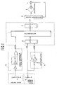
- Fig. 1 shows a hardware configuration of the accelerator control system including a microcomputer 1.
- the microcomputer 1 outputs a control signal indicative of a target throttle valve opening rate to a throttle valve servo system through a digital-to-analog converter 2.
- This servo system is made up of a servo motor 3 for opening or closing a throttle valve, a throttle valve position sensor 4 such as a potentiometer for detecting the opening rate of the throttle valve, and a servomotor driver 5 for comparing the control signal indicative of the target throttle valve opening rate outputted from the microcomputer 1 with the output signal indicative of the actual opening rate outputted from the throttle valve position sensor 4 in order to drive the servomotor 3 in the -normal or reverse direction so that the actual throttle valve opening rate detected by the position sensor matches the target rate.
- an accelerator pedal stroke sensor 6 such as potentiometer for detecting the stroke of an accelerator pedal and an accelerator pedal switch 7 turned on by a spring (not shown) when the accelerator pedal is released to the original (zero-stroke) position and turned off when the pedal is depressed by the driver.
- the accelerator pedal stroke sensor 6 outputs an accelerator pedal stroke signal ASS to the microcomputer 1 through an analog-to-digital converter 8. Additionally, this accelerator pedal stroke signal ASS is differentiated through a differentiator 9 including an operational amplifier into an accelerator pedal stroke displacement speed signal DASS. This accelerator pedal stroke speed signal DASS is also applied to the microcomputer 1 through the analog-to-digital converter 8.
- the timing when the accelerator pedal switch 7 is-turned from on to off, that is, when the accelerator pedal is depressed to accelerate the vehicle is detected throguh an accelerator pedal depression timing detector 10.
- the accelerator pedal depression timing signal (ADTS) detected by this detector 10 is also applied to the microcomputer 1 directly.
- the accelerator pedal depression timing detector 10 detects the rising edge of the signal from the -accelerator pedal switch 7 and output a pulse signal with a small pulse width.
- the microcomputer 1 determines target throttle valve opening rates and outputs control signals corresponding thereto to the servomotor driver 5.
- a plurality of target throttle valve opening rates are predetermined and previously stored in the memory unit of the microcomputer 1 with the accelerator pedal stroke as variable in the form of function tables.
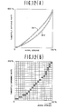
- control characteristics CB1 and CB2 representative of relationship between accelerator pedal stroke and throttle valve opening rate are predetermined, as depicted in Fig. 2.
- Both the control characteristics CB1 and CB2 are determined to be linear, by way of example, in which throttle valve opening rate increases in proportion to accelerator pedal stroke.
- the characteristics CBl are so determined as to be roughly the same as in the conventional accelerator pedal control device in which the accelerator pedal is directly linked to the throttle valve mechanically. Therefore, in the characteristics CB 1 , throttle valve opening rate increases relatively sharply with increasing accelerator pedal stroke. In such characteristics, the driver can accelerate the vehicle quickly or ordinarily.
- the characteristics CB2 are so determined that throttle valve opening rate increases relatively gently with increasing accelerator pedal stroke. In such characteristics, the driver can accelerate the vehicle gently and finely.
- the control characteristics CB1 are called ordinary control characteristics; the control characteristics CB2 are called fine control characteristics.
- the accelerator system under the ordinary vehicle travelling conditions, the accelerator system is controlled in accordance with the ordinary control characteristics CB1.
- the accelerator system is controlled in accordance with the fine control characteristics CB2 under-the following vehicle travelling conditions: (1) the accelerator pedal is depressed beginning from the position where the pedal is returned to the original zero position; (2) the accelerator pedal stroke is below a predetermined reference value within a sufficiently short period To after the accelerator pedal has been depressed; and (3) the accelerator pedal stroke speed is also below a predetermined reference value within the period To.
- the accelerator control characteristics are switched from the ordinary characteristics CB1 to the fine characteristics CS2, when the voltage levels of the detected accelerator pedal stroke signal ASS and the detected accelerator pedal stroke speed signal DASS do not both exceed the reference voltage levels ASS1 and DASS1 respectively within the predetermined time period To after the accelerator pedal depression timing detector 10 outputs an accelerator pedal depression timing signal ADTS.
- the accelerator pedal depression timing signal ADTS is generated.
- the microcomputer 1 activates a timer function provided therewithin in order to count a predetermined time period To. While this timer function is in operation, the accelerator pedal stroke signals ASS and the accelerator pedal stroke displacement speed signals DASS are both repeatedly sampled and updated. These signals are then compared with the reference signal thereof ASS1 and DASS1 in voltage level.
- the ordinary control characteristics CB1 is changed to the fine control characteristics CB2 immediately after the time To has elapsed.
- the accelerator system is controlled in accordance with the ordinary control characteristics CB1.
- the above-mentioned two reference values ASS1 -and DASS1 are both determined on the basis of various experiments. These experiments have been made when a number of drivers depress the accelerator pedal, under the intension of finely depressing the accelerator pedal, to drive the vehicle a little distance forward repeatedly.
- the reference accelerator pedal stroke ASS1 is determined to be approximately 20 percent of the position where the pedal is fully depressed; the reference accelerator pedal stroke speed DASSl is determined to be a speed at which the pedal is fully depressed during approximately one second.
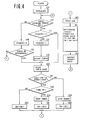
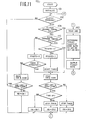
- accelerator pedal stroke signals ASS and accelerator pedal stroke speed signals DASS are both repeatedly read into the microcomputer (in block 120) and compared with the two reference values ASS1 and DASS1, separately (in block 121). If either or both of the two signals ASS and DASS exceed the reference values ASS1 and DASS1 (in block 121) respectively, the timer function is stopped (in block 124) and then the ordinary control characteristics CBl are stored in the register (in block 132).
- control set the flag FFADTS to "0" and then checks whether the timer function is in operation or not (in block 115). If the timer function is counting the predetermined time period To, the signals ASS and DASS are . both read again.
- either of the control characteristics CB1 or CB2 are always stored in the register in order to control throttle valve opening rates according to the accelerator pedal strokes, and the above operations are executed repeatedly at a high speed.
- control reads the accelerator pedal stroke signal ASS (in block 140) and determines an appropriate throttle valve opening rate corresponding to the read stroke signal ASS (in block 141).
- the appropriate throttle valve opening rate is determined in accordance with well-known table look-u p method and interpolation calculations or operations.
- the characteristics CBl or CB2 are listed on the basis of the relationship between accelerator pedal stroke and throttle valve opening rate as already described with reference to Fig. 2.
- a signal indicative of the determined target throttle valve opening rate is outputted (in block 142) to the servomotor driver 5 in order to drive the servomotor 3 so that the actual throttle valve opening rate matches the target opening rate.
- the control characteristics are changed from the ordinary ones CBl to the fine ones CB2 only when both of accelerator pedal stroke signal ASS and the accelerator pedal stroke speed signal DASS do not exceed the respective first reference signals ASS1 or DASS1 in voltage level within ia predetermined time period To after the accelerator pedal is first depressed. Further, the changed fine control characteristics CB2 are kept as they are until the accelerator pedal is depressed again. In other words, whenever the accelerator pedal is depressed by the driver, the characteristics are adjusted only once according to the pedal stroke and the pedal stroke speed.
- the control characteristics are changed from the ordinary ones CB1 to the fine ones CB2 as in the first embodiment but returned to the ordinary ones CBl while the pedal is kept depressed, when either or both of the accelerator pedal stroke signal ASS and the accelerator pedal stroke speed signal DASS exceed the respective second reference signals ASS2 and DASS2.
- the characteristics are changed from the ordinary ones CB1 to the fine ones CB2 or vice versa according to the pedal stroke and the pedal stroke speed values.
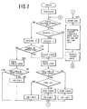
- the microcomputer 1 activates a timer function provided therewithin in order to count a predetermined period To. While this timer function is in operation, the accelerator pedal stroke signal ASS and the accelerator pedal stroke displacement speed signal DASS are repeatedly sampled and updated. These signals are then compared with the reference values thereof ASS1 and DASSl. If the two updated signals ASS and DASS are both do not exceed the reference signals ASS1 and DASSl respectively and continuously during the counted time period To, the ordinary characteristics CBl is changed to the fine characteristics CB2 immediately after the time To has elapsed. In the case where either or both of the two 'signals ASS and DASS exceed the reference signals ASS1 and DASS1 respectively, the accelerator system is of course controlled in accordance with the ordinary characteristics CB1.
- Fig. 6A In which the accelerator pedal stroke ASS is taken on the abscissa and the accelerator pedal stroke speed DASS is taken on the ordinate.
- the label R 1 designates a first range where the accelerator pedal stroke signal ASS does not exceed first reference signal ASS1 and the accelerator pedal stroke speed signal DASS does not also exceed the first reference signal DASS1.
- the fine characteristics CB2 are selected.
- the label R 2 designates a second range where the signal ASS exceeds the second referencesignal ASS2 or the signal DASS exceeds the second reference signal DASS2 in voltage level. When either or both of the two signal ASS and DASS exceed these two reference signals ASS2 and DASS2 even after the fine characteristics CB2 have been selected, the fine control characteristics CB2 are returned to the ordinary control characteristics CB1.
- the label R 3 designates a third range where the stroke signal ASS lies in voltage level between ASS1 and ASS2 and further below DASS2 or the stroke speed signal DASS lies in voltage level between DASS1 and DASS2 and further below ASS2.
- the control characteristics CB1 are kept stored as they are in the microcomputer 1. However, once the fine characteristics CB2 have been selected within the range R 1 , the characteristics CB2 are kept stored as they are in the microcomputer 1 within the third range R 3 .
- Fig. 6(B) shows another modification of these control characteristic ranges.
- the fine characteristics CB2 are kept stored as they are without returning them to the ordinary characteristics CBl.
- the above-mentioned various reference values ASS1, ASS2, DASS1, DASS2 and ' DASS3 are all determined on the basis of various experiments. These experiments have been made when a number of drivers depress the accelerator pedal, under the intension of finely depressing the accelerator pedal, to drive the vehicle a little distance forward repeatedly.
- the first reference accelerator pedal stroke ASS1 is determined to be approximately 20 percent of the position where the pedal is fully depressed and the second reference accelerator pedal stroke ASS2 is determined to be approximately 40 percent of the same position.
- the first reference accelerator pedal stroke speed DASS1 is determined to be a speed at which the pedal is fully depressed during approximately one second; the second reference accelerator pedal stroke speed DASS2 is determined to be a speed at which the pedal is fully depressed during approximately 0.5 seconds; and the third reference accelerator pedal stroke speed DASS3 is determined to be a speed at which the pedal is fully depressed during approximately 2 seconds.
- control characteristics are changed to the ordinary control characteristics CB1 (in block 152). If both of these signals do not exceed the second reference signals (in block 151), the control does not change the control characteristics.
- a third embodiment of the accelerator control system according to the present invention will be described hereinbelow.
- the feature of this third embodiment is to change the control characteristics from the ordinary ones CB1 to the fine ones CB2 under the consideration of the engagement/ disengagement conditions of the clutch.
- the control characteristics are not changed, irrespective of the stroke or stroke speed of the accelerator pedal, that is, even when the system determines that the characteristics ' should be changed to appropriate characteristics CB1 or CB2.
- the control procedure to change the characteristics is executed only when the clutch is being engaged.
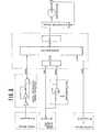
- Fig. 8 shows the system configuration of the third embodiment of the system according to the present invention, in which only a clutch siwtch 11 is provided in addition to the elements shown in Fig. 1 (the first and second embodiments).
- This clutch.switch 11 is closed when the clutch is being released or engaged but opened when the clutch is being depressed or disengaged.
- the clutch timing signal CLS is also inputted to the microcomputer 1.
- control When control is initialized (in block 101), control first checks whether the clutch switch 11 is on (engaged) or off (disengaged) (in block 102). If the clutch switch 11 is off; that is, the clutch is depressed or disengaged, control advances the steps directly to the step where the accelerator pedal stroke signal ASS is read to determine an appropriate throttle valve opening rate according to the pedal stroke (in block 140) without executing the steps for determining whether the driver depresses the accelerator pedal finely; that is, for selecting the fine control characteristics CB2. If the clutch switch 11 is on; that is, the clutch is released or engaged, control executes the various steps for selecting the fine control characteristics CB2 as already described in the second embodiment.
- the above-mentioned third embodiment has an advantage which can settle the following problems: In the state where the clutch is depressed and therefore disengaged, the accelerator pedal is generally fully released or is depressed only a little. Under these conditions, the driver does not necessarily want the fine control characteristics CB2. Therefore, when the fine control characteristics CB2 have been selected with the clutch disengaged, there exist a problem in that it is impossible for the driver to quickly accelerate the vehicle immediately after the clutch has been engaged by the driver.
- a fourth embodiment of the accelerator control system according to the present invention will be described hereinbelow.
- the feature of this fourth embodiment is to change the control characteristics from the ordinary ones CS1 to the fine ones CB2 under the consideration of engagement/disengagement conditions of the clutch and further clutch engagement timing having priority over accelerator pedal depression timing.
- the control characteristics are not changed to the fine control characteristics CB2, irrespective of the stroke and the stroke speed of the accelerator pedal as in the third embodiment.
- the control procedure for changing the ordinary control characteristics CB2 to the fine control characteristics CB2 is executed, irrespective of the presence or absence of the accelerator pedal depression timing signal, that is, of whether the accelerator pedal is first depressed or not.
- the step for counting the predetermined time period To is executed in response to the clutch engagement timing signal CLS having priority over the accelerator pedal depression timing signal ADTS.
- Fig. 10 shows the configuration of the fourth embodiment of the system according to the present invention, in which only a clutch engagement timing detector 12 is provided in addition to the elements shown in Fig. 8 (the third embodiment).
- This detector 12 is connected to the clutch switch 11 for detecting the timing when the clutch is engaged and outputs a pulse signal CLTS with a short pulse width to the microcomputer 1.
- control When control is initialized (in block 101), control first checks whether the clutch switch 11 is on (engaged) or off (disengaged) (in block 102). If the clutch switch 11 is off, that is, the clutch is depressed or disengaged, control advances the steps directly to the step where the accelerator pedal stroke signal ASS is read (in block 140) without executing the steps for determining whether the driver depreses the accelerator pedal finely. If the clutch switch 11 is on; that is, the clutch is released or engaged, control first checks whether the clutch engagement timing signal CLTT is present or not (in block 103).
- control skips the step for checking the presence of the accelerator pedal depression timing signal ADTS (block 110), that is, disregards the presence or absence of the accelerator pedal depression timing signal ADTS. Thereafter, control executes the same processing steps for determining whether the characteristics should be changed to the fine ones CB2 or not. Further, when the clutch engagement timing signal ADTS is absent (in block 103), control of course executes the step for determining whether the accelerator pedal depression timing signal ADTS is present or not (in block 110). Therefore, in the case when the accelerator pedal stroke ASS and the accelerator pedal stroke speed DASS do not both exceed the first reference values ASS1 and DASS1 within the predetermined time period To after the clutch has been engaged, the fine characteristics CB2 are selected, in the same way as in-the first embodiment.
- This embodiment results from the fact that whenever the driver depresses the accelerator pedal finely, the timing when the pedal is depressed is closely related to the timing when the clutch is released.
- the driver drives the vehicle a little distance forward repeatedly on a busy load, he usually engages the 'clutch a little, immediately before he depresses the accelerator pedal. Therefore, it is possible for the driver to drive the vehicle in accordance with the fine control characteristics, immediately after the accelerator pedal has been depressed.
- the reference numeral 13 denotes a lamp indicative of the fact that the ordinary control characteristics CB1 is being selected and the reference numeral 14 denotes another lamp indicative of the fact that the fine control characteristics CB2 is being selected.
- These indicator lamps 13 and 14 are disposed at an appropriate position on the dashboard.
- the driver when the driver once depresses the accelerator pedal finely to drive the vehicle a little distance forward, since the ordinary control characteristics representative of relationship between the throttle valve opening rate and the accelerator pedal stroke are switched automatically to the fine control characteristics suitable to fine accelerator pedal depression, the driver can easily control vehicle speed in driving his vehicle on a busy road, thus preventing the vehicle vibrations caused by the change in engine torque generated when the driver depresses the accelerator pedal irritatingly while the vehicle is travelling at a low speed on a busy road. Additionally, it is also possible to prevent driver's discomfort due to vehicle vibration and driver's irritation due to fatigue caused by the fact that the driver must depress the accelerator pedal finely and repeatedly by his foot. However, in the ordinary vehicle travelling conditions, since the fine control characteristics are returned to the ordinary characteristics automatically, the driver of course can accelerate the vehicle as is usual.
Landscapes
- Engineering & Computer Science (AREA)
- Chemical & Material Sciences (AREA)
- Combustion & Propulsion (AREA)
- Mechanical Engineering (AREA)
- General Engineering & Computer Science (AREA)
- Control Of Throttle Valves Provided In The Intake System Or In The Exhaust System (AREA)
- Electrical Control Of Air Or Fuel Supplied To Internal-Combustion Engine (AREA)
Applications Claiming Priority (8)
| Application Number | Priority Date | Filing Date | Title |
|---|---|---|---|
| JP23043382A JPS59122745A (ja) | 1982-12-28 | 1982-12-28 | 車両用アクセル制御装置 |
| JP20225182U JPS59103845U (ja) | 1982-12-28 | 1982-12-28 | 車両用アクセル制御装置 |
| JP23043482A JPS59122746A (ja) | 1982-12-28 | 1982-12-28 | 車両用アクセル制御装置 |
| JP230433/82 | 1982-12-28 | ||
| JP202251/82U | 1982-12-28 | ||
| JP230434/82 | 1982-12-28 | ||
| JP978/83 | 1983-01-07 | ||
| JP97883A JPS59126036A (ja) | 1983-01-07 | 1983-01-07 | 車両用アクセル制御装置 |
Publications (3)
| Publication Number | Publication Date |
|---|---|
| EP0114401A2 true EP0114401A2 (de) | 1984-08-01 |
| EP0114401A3 EP0114401A3 (en) | 1984-11-07 |
| EP0114401B1 EP0114401B1 (de) | 1986-12-30 |
Family
ID=27453296
Family Applications (1)
| Application Number | Title | Priority Date | Filing Date |
|---|---|---|---|
| EP83113143A Expired EP0114401B1 (de) | 1982-12-28 | 1983-12-27 | Drosselklappensteuerungssystem für Motorfahreug |
Country Status (3)
| Country | Link |
|---|---|
| US (1) | US4597049A (de) |
| EP (1) | EP0114401B1 (de) |
| DE (1) | DE3368559D1 (de) |
Cited By (5)
| Publication number | Priority date | Publication date | Assignee | Title |
|---|---|---|---|---|
| DE3504181A1 (de) * | 1984-02-07 | 1985-08-14 | Nissan Motor Co., Ltd., Yokohama, Kanagawa | Vorrichtung zur steuerung der ansaugluftmenge von brennkraftmaschinen in kraftfahrzeugen |
| DE3447629A1 (de) * | 1984-12-28 | 1986-07-03 | Fujitsu Ltd., Kawasaki, Kanagawa | Signalverarbeitungssystem fuer einen kraftfahrzeug-beschleunigungsfuehler |
| EP0230745A3 (en) * | 1985-12-19 | 1988-10-19 | Nippondenso Co., Ltd. | Vehicle acceleration control system vehicle acceleration control system |
| EP1975390A1 (de) * | 2007-03-30 | 2008-10-01 | HONDA MOTOR CO., Ltd. | Steuerung der Antriebsstärke |
| CN104847508A (zh) * | 2015-03-27 | 2015-08-19 | 山西文正卓越汽车电喷装置有限公司 | 机动车的发动机的控制方法及发动机 |
Families Citing this family (28)
| Publication number | Priority date | Publication date | Assignee | Title |
|---|---|---|---|---|
| JPS60163731A (ja) * | 1984-02-07 | 1985-08-26 | Nissan Motor Co Ltd | 車速制御装置 |
| JPS61171843A (ja) * | 1985-01-24 | 1986-08-02 | Mazda Motor Corp | エンジンのスロツトル弁制御装置 |
| US4718380A (en) * | 1985-05-27 | 1988-01-12 | Nissan Motor Company, Limited | System and method for controlling the opening angle of a throttle valve according to the position of an accelerator for an automotive vehicle |
| JP2564275B2 (ja) | 1986-05-09 | 1996-12-18 | 株式会社日立製作所 | 状態適応型内燃機関制御システム |
| US5189621A (en) * | 1987-05-06 | 1993-02-23 | Hitachi, Ltd. | Electronic engine control apparatus |
| JPS6412935A (en) * | 1987-07-02 | 1989-01-17 | Mitsubishi Electric Corp | Constant-speed travel device for vehicle |
| JP2559480B2 (ja) * | 1988-11-07 | 1996-12-04 | 株式会社日立製作所 | 電子式弁開度制御装置 |
| WO1990006434A1 (en) * | 1988-11-29 | 1990-06-14 | Robert Bosch Gmbh | Device for detecting and correcting faulty disconformity between desired and actual positions of a servo controlled regulating member |
| JP2706790B2 (ja) * | 1988-11-30 | 1998-01-28 | スズキ株式会社 | 連続可変変速機の回転数制御装置 |
| DE3844353A1 (de) * | 1988-12-30 | 1990-07-05 | Bosch Gmbh Robert | Verfahren und vorrichtung fuer ein elektronisch-mechanisches fahrpedal |
| US5109819A (en) * | 1991-03-29 | 1992-05-05 | Cummins Electronics Company, Inc. | Accelerator control system for a motor vehicle |
| JP3073591B2 (ja) * | 1992-03-17 | 2000-08-07 | マツダ株式会社 | エンジンの制御装置 |
| DE4223782B4 (de) * | 1992-07-18 | 2010-05-06 | Bayerische Motoren Werke Aktiengesellschaft | Ansaugluftmengensteuereinrichtung für eine Brennkraftmaschine eines Kraftfahrzeugs |
| DE4230925C1 (de) * | 1992-09-16 | 1994-02-24 | Bosch Gmbh Robert | Digitaler Lageregler für Fahrzeuge |
| JPH0771412A (ja) * | 1993-09-03 | 1995-03-17 | Kubota Corp | 作業車の油圧アクチュエータ操作構造 |
| US5521825A (en) * | 1993-10-06 | 1996-05-28 | General Motors Corporation | Engine inlet air valve positioning |
| JPH08338270A (ja) * | 1995-06-09 | 1996-12-24 | Nippondenso Co Ltd | 車両用制御装置 |
| US5775293A (en) * | 1996-10-01 | 1998-07-07 | Cummins Engine Co., Inc. | Electronic throttle pedal nonlinear filter |
| FR2757900B1 (fr) * | 1996-12-30 | 1999-02-05 | Renault | Procede de commande electronique d'un papillon motorise dans un moteur a combustion interne |
| DE19730906A1 (de) * | 1997-07-18 | 1999-01-28 | Daimler Benz Ag | Verfahren zur Einstellung der Drosselklappe und/oder Einspritzmenge einer Brennkraftmaschine eines Kraftfahrzeuges an die Vorgabe des Fahrzeugführers |
| DE10150422B4 (de) * | 2001-10-11 | 2012-04-05 | Robert Bosch Gmbh | Verfahren und Vorrichtung zur Ermittlung eines Fahrerwunsches |
| WO2003074311A1 (de) * | 2002-03-07 | 2003-09-12 | Josef Bergmeister | Fahrzeugantrieb fahrzeugantriebsverfahren motorsteuerung und motorsteuerungsverfahren |
| SE526382C2 (sv) * | 2004-01-16 | 2005-09-06 | Scania Cv Abp | Anordning samt förfarande för dämpning |
| GR1005429B (el) * | 2005-12-09 | 2007-02-01 | Ενισχυτης σηματος επιταχυνσης-αυτοματος πιλοτος για αυτοκινητα νεας τεχνολογιας | |
| US20140207353A1 (en) * | 2005-12-09 | 2014-07-24 | Stamatios Boulekos | Acceleration adjuster for vehicles with an electronic accelerator |
| FR2934065B1 (fr) * | 2008-07-17 | 2010-08-27 | Airbus France | Dispositif pour la determination de la position d'une manette des gaz dans un aeronef |
| US9085237B2 (en) * | 2011-10-03 | 2015-07-21 | Fuji Jukogyo Kabushiki Kaisha | Speed limiter |
| US11235885B2 (en) * | 2019-12-20 | 2022-02-01 | Pratt & Whitney Canada Corp. | Method and system for determining a throttle position of an aircraft |
Family Cites Families (27)
| Publication number | Priority date | Publication date | Assignee | Title |
|---|---|---|---|---|
| US3893537A (en) * | 1970-07-03 | 1975-07-08 | Aisin Seiki | Apparatus for control of a vehicle constant speed mechanism |
| JPS5141177B2 (de) * | 1972-03-06 | 1976-11-08 | ||
| JPS5228172B2 (de) * | 1974-03-18 | 1977-07-25 | ||
| DE2436982C2 (de) * | 1974-08-01 | 1984-06-28 | Robert Bosch Gmbh, 7000 Stuttgart | Anordnung zur Einstellung der Drosselklappe eines Verbrennungsmotors |
| JPS5825853B2 (ja) * | 1975-05-23 | 1983-05-30 | カブシキガイシヤ ニツポンジドウシヤブヒンソウゴウケンキユウシヨ | 内燃機関のスロツトル弁制御装置 |
| DE2609842A1 (de) * | 1976-03-10 | 1977-09-15 | Bosch Gmbh Robert | Einrichtung zum regeln der fahrgeschwindigkeit eines mit einem verbrennungsmotor angetriebenen fahrzeuges |
| FR2356007A1 (fr) * | 1976-06-24 | 1978-01-20 | Henry Jancelin Georges | Dispositif de servo-commande electronique de l'admission des gaz dans les moteurs a explosion |
| SE434932B (sv) * | 1977-03-30 | 1984-08-27 | Vdo Schindling | Anordning for reglering av ett motorfordons korhastighet |
| US4113046A (en) * | 1977-06-20 | 1978-09-12 | Arpino R | Vehicle fuel economy indicator |
| DE2732905C3 (de) * | 1977-07-21 | 1994-02-24 | Vdo Schindling | Einrichtung zum Regeln der Fahrgeschwindigkeit eines Kraftfahrzeugs |
| DE2751125A1 (de) * | 1977-11-16 | 1979-05-17 | Bosch Gmbh Robert | Steuereinrichtung fuer eine brennkraftmaschine |
| DE2839467C2 (de) * | 1978-09-11 | 1985-01-31 | Vdo Adolf Schindling Ag, 6000 Frankfurt | Einrichtung zur Übertragung der Stellung eines die Fahrgeschwindigkeit eines Kraftfahrzeugs steuernden, durch den Fahrzeugführer betätigbaren Steuerelements |
| DE2843456C2 (de) * | 1978-10-05 | 1984-11-15 | Vdo Adolf Schindling Ag, 6000 Frankfurt | Stellungsgeber zum Beeinflussen der Fahrgeschwindigkeit eines Kraftfahrzeugs |
| JPS55123327A (en) * | 1979-03-16 | 1980-09-22 | Nippon Denso Co Ltd | Throttle valve controlling system for internal combustion engine |
| FR2453048A1 (fr) * | 1979-04-05 | 1980-10-31 | Sejournet Jerome | Appareil regulateur de la vitesse d'un vehicule automobile |
| DE2926106C2 (de) * | 1979-06-28 | 1987-03-19 | Volkswagen AG, 3180 Wolfsburg | Verfahren und Anordnung zum Betrieb einer Fahrzeug-Brennkraftmaschine |
| DE2926105A1 (de) * | 1979-06-28 | 1981-01-08 | Volkswagenwerk Ag | Einrichtung an einer brennkraftmaschine mit einer kraftstoffzumesseinrichtung |
| FR2460224A1 (fr) * | 1979-06-29 | 1981-01-23 | Renault | Regulateur d'allure pour vehicule automobile |
| GB2068456B (en) * | 1980-01-30 | 1983-09-28 | Lucas Industries Ltd | Internal combustion engine throttle valve control linkage |
| IT1128017B (it) * | 1980-02-05 | 1986-05-28 | Fiat Auto Spa | Siatema e metodo di controllo per veicoli a motore muniti di una trasmissione a ruota libera |
| JPS56132428A (en) * | 1980-03-19 | 1981-10-16 | Hitachi Ltd | Controller of intake air amount to internal combustion engine |
| DE3019562A1 (de) * | 1980-05-22 | 1981-11-26 | Daimler-Benz Ag, 7000 Stuttgart | Vorrichtung zum steuern einer brennkraftmaschine |
| JPS5744750A (en) * | 1980-08-28 | 1982-03-13 | Aisin Seiki Co Ltd | Transducer type accelerator |
| US4419729A (en) * | 1980-10-27 | 1983-12-06 | The Bendix Corporation | Automatic speed control for heavy vehicles |
| DE3109638A1 (de) * | 1981-03-13 | 1982-09-23 | Vdo Adolf Schindling Ag, 6000 Frankfurt | Schutz- und ueberwachungseinrichtung fuer steuerschaltungsanordnungn in kraftfahrzeugen |
| DE3130099C2 (de) * | 1981-07-30 | 1983-05-19 | Vdo Adolf Schindling Ag, 6000 Frankfurt | Einrichtung zur elektrischen Regelung der Geschwindigkeit eines Kraftfahrzeugs |
| US4470396A (en) * | 1982-12-02 | 1984-09-11 | Mikuni Kogyo Kabushiki Kaisha | Internal combustion engine control system with means for reshaping of command from driver's foot pedal |
-
1983
- 1983-12-23 US US06/564,682 patent/US4597049A/en not_active Expired - Lifetime
- 1983-12-27 DE DE8383113143T patent/DE3368559D1/de not_active Expired
- 1983-12-27 EP EP83113143A patent/EP0114401B1/de not_active Expired
Cited By (7)
| Publication number | Priority date | Publication date | Assignee | Title |
|---|---|---|---|---|
| DE3504181A1 (de) * | 1984-02-07 | 1985-08-14 | Nissan Motor Co., Ltd., Yokohama, Kanagawa | Vorrichtung zur steuerung der ansaugluftmenge von brennkraftmaschinen in kraftfahrzeugen |
| DE3447629A1 (de) * | 1984-12-28 | 1986-07-03 | Fujitsu Ltd., Kawasaki, Kanagawa | Signalverarbeitungssystem fuer einen kraftfahrzeug-beschleunigungsfuehler |
| DE3447629C2 (de) * | 1984-12-28 | 1992-05-27 | Isuzu Motors Ltd., Tokio/Tokyo, Jp | |
| EP0230745A3 (en) * | 1985-12-19 | 1988-10-19 | Nippondenso Co., Ltd. | Vehicle acceleration control system vehicle acceleration control system |
| EP1975390A1 (de) * | 2007-03-30 | 2008-10-01 | HONDA MOTOR CO., Ltd. | Steuerung der Antriebsstärke |
| US7702448B2 (en) | 2007-03-30 | 2010-04-20 | Honda Motor Co., Ltd. | Driving amount controller |
| CN104847508A (zh) * | 2015-03-27 | 2015-08-19 | 山西文正卓越汽车电喷装置有限公司 | 机动车的发动机的控制方法及发动机 |
Also Published As
| Publication number | Publication date |
|---|---|
| EP0114401B1 (de) | 1986-12-30 |
| EP0114401A3 (en) | 1984-11-07 |
| DE3368559D1 (en) | 1987-02-05 |
| US4597049A (en) | 1986-06-24 |
Similar Documents
| Publication | Publication Date | Title |
|---|---|---|
| EP0114401B1 (de) | Drosselklappensteuerungssystem für Motorfahreug | |
| US5713428A (en) | Apparatus for regulating the speed of a motor vehicle | |
| US5839534A (en) | System and method for intelligent cruise control using standard engine control modes | |
| US5774820A (en) | Method and apparatus for limiting the speed of a motor vehicle | |
| US4969103A (en) | Speed control apparatus for an automotive vehicle with creep control | |
| US5020645A (en) | Vehicle clutch control system | |
| US5845726A (en) | Vehicle driving force control apparatus | |
| US6542804B2 (en) | Automatic transmission controller having automatic-shifting-to-neutral control | |
| EP0735957B1 (de) | Kupplungs-steuerungssystem | |
| EP0106360A2 (de) | Gaspedal-Steuersystem für ein Kraftfahrzeug | |
| US5051905A (en) | System and method for automatically controlling vehicle speed to desired cruise speed | |
| EP0602685B1 (de) | Steuervorrichtung für ein automatisiertes Getriebe eines Nutzfahrzeuges | |
| EP0364276A2 (de) | Vorrichtung zur Steuerung von Getriebe und Kupplung von Fahrzeugen | |
| US4747326A (en) | Speed control system | |
| US5012419A (en) | System and method for automatically controlling vehicle speed to desired cruise speed | |
| US5595550A (en) | Clutch control system | |
| EP0335333A2 (de) | System und Verfahren zur Steuerung der Fahrzeug-Reisegeschwindigkeit auf eine gewünschte Geschwindigkeit für Fahrzeuge | |
| EP0323070A2 (de) | Integrierte Motorkupplungs-Steuerung | |
| US5434786A (en) | Vehicle speed controlling apparatus and method for controlling speed of vehicle with automatic transmission | |
| US5040121A (en) | System and method for automatically controlling vehicle speed to desired cruise speed | |
| JPH0211452B2 (de) | ||
| EP0650000A1 (de) | Elektronische Steueranlage für ein stufenlos automatisches Getriebe eines Kraftfahrzeugs, insbesondere eines Automobils | |
| EP0649766A1 (de) | Verfahren und Apparat zur Regelung der Geschwindigkeit eines Fahrzeuges | |
| KR950011275B1 (ko) | 차량용 엔진브레이크 자동 제어 장치 | |
| GB2283338A (en) | Vehicle cruise control resume function |
Legal Events
| Date | Code | Title | Description |
|---|---|---|---|
| PUAI | Public reference made under article 153(3) epc to a published international application that has entered the european phase |
Free format text: ORIGINAL CODE: 0009012 |
|
| 17P | Request for examination filed |
Effective date: 19831227 |
|
| AK | Designated contracting states |
Designated state(s): DE FR GB |
|
| PUAL | Search report despatched |
Free format text: ORIGINAL CODE: 0009013 |
|
| AK | Designated contracting states |
Designated state(s): DE FR GB |
|
| RAP1 | Party data changed (applicant data changed or rights of an application transferred) |
Owner name: NISSAN MOTOR CO., LTD. |
|
| GRAA | (expected) grant |
Free format text: ORIGINAL CODE: 0009210 |
|
| AK | Designated contracting states |
Kind code of ref document: B1 Designated state(s): DE FR GB |
|
| PG25 | Lapsed in a contracting state [announced via postgrant information from national office to epo] |
Ref country code: FR Free format text: THE PATENT HAS BEEN ANNULLED BY A DECISION OF A NATIONAL AUTHORITY Effective date: 19861230 |
|
| REF | Corresponds to: |
Ref document number: 3368559 Country of ref document: DE Date of ref document: 19870205 |
|
| EN | Fr: translation not filed | ||
| PLBE | No opposition filed within time limit |
Free format text: ORIGINAL CODE: 0009261 |
|
| STAA | Information on the status of an ep patent application or granted ep patent |
Free format text: STATUS: NO OPPOSITION FILED WITHIN TIME LIMIT |
|
| 26N | No opposition filed | ||
| GBPC | Gb: european patent ceased through non-payment of renewal fee | ||
| PG25 | Lapsed in a contracting state [announced via postgrant information from national office to epo] |
Ref country code: GB Free format text: LAPSE BECAUSE OF NON-PAYMENT OF DUE FEES Effective date: 19881122 |
|
| PGFP | Annual fee paid to national office [announced via postgrant information from national office to epo] |
Ref country code: DE Payment date: 20030109 Year of fee payment: 20 |