EP0112574A1 - Seringue préremplie à double compartiment - Google Patents
Seringue préremplie à double compartiment Download PDFInfo
- Publication number
- EP0112574A1 EP0112574A1 EP83113098A EP83113098A EP0112574A1 EP 0112574 A1 EP0112574 A1 EP 0112574A1 EP 83113098 A EP83113098 A EP 83113098A EP 83113098 A EP83113098 A EP 83113098A EP 0112574 A1 EP0112574 A1 EP 0112574A1
- Authority
- EP
- European Patent Office
- Prior art keywords
- valve
- syringe
- piston
- liquid
- chamber
- Prior art date
- Legal status (The legal status is an assumption and is not a legal conclusion. Google has not performed a legal analysis and makes no representation as to the accuracy of the status listed.)
- Withdrawn
Links
Images


Classifications
-
- A—HUMAN NECESSITIES
- A61—MEDICAL OR VETERINARY SCIENCE; HYGIENE
- A61M—DEVICES FOR INTRODUCING MEDIA INTO, OR ONTO, THE BODY; DEVICES FOR TRANSDUCING BODY MEDIA OR FOR TAKING MEDIA FROM THE BODY; DEVICES FOR PRODUCING OR ENDING SLEEP OR STUPOR
- A61M5/00—Devices for bringing media into the body in a subcutaneous, intra-vascular or intramuscular way; Accessories therefor, e.g. filling or cleaning devices, arm-rests
- A61M5/178—Syringes
- A61M5/31—Details
- A61M5/315—Pistons; Piston-rods; Guiding, blocking or restricting the movement of the rod or piston; Appliances on the rod for facilitating dosing ; Dosing mechanisms
- A61M5/31596—Pistons; Piston-rods; Guiding, blocking or restricting the movement of the rod or piston; Appliances on the rod for facilitating dosing ; Dosing mechanisms comprising means for injection of two or more media, e.g. by mixing
-
- A—HUMAN NECESSITIES
- A61—MEDICAL OR VETERINARY SCIENCE; HYGIENE
- A61M—DEVICES FOR INTRODUCING MEDIA INTO, OR ONTO, THE BODY; DEVICES FOR TRANSDUCING BODY MEDIA OR FOR TAKING MEDIA FROM THE BODY; DEVICES FOR PRODUCING OR ENDING SLEEP OR STUPOR
- A61M5/00—Devices for bringing media into the body in a subcutaneous, intra-vascular or intramuscular way; Accessories therefor, e.g. filling or cleaning devices, arm-rests
- A61M5/178—Syringes
- A61M5/24—Ampoule syringes, i.e. syringes with needle for use in combination with replaceable ampoules or carpules, e.g. automatic
- A61M5/2422—Ampoule syringes, i.e. syringes with needle for use in combination with replaceable ampoules or carpules, e.g. automatic using emptying means to expel or eject media, e.g. pistons, deformation of the ampoule, or telescoping of the ampoule
- A61M5/2429—Ampoule syringes, i.e. syringes with needle for use in combination with replaceable ampoules or carpules, e.g. automatic using emptying means to expel or eject media, e.g. pistons, deformation of the ampoule, or telescoping of the ampoule by telescoping of ampoules or carpules with the syringe body
-
- A—HUMAN NECESSITIES
- A61—MEDICAL OR VETERINARY SCIENCE; HYGIENE
- A61M—DEVICES FOR INTRODUCING MEDIA INTO, OR ONTO, THE BODY; DEVICES FOR TRANSDUCING BODY MEDIA OR FOR TAKING MEDIA FROM THE BODY; DEVICES FOR PRODUCING OR ENDING SLEEP OR STUPOR
- A61M5/00—Devices for bringing media into the body in a subcutaneous, intra-vascular or intramuscular way; Accessories therefor, e.g. filling or cleaning devices, arm-rests
- A61M5/178—Syringes
- A61M5/28—Syringe ampoules or carpules, i.e. ampoules or carpules provided with a needle
- A61M5/284—Syringe ampoules or carpules, i.e. ampoules or carpules provided with a needle comprising means for injection of two or more media, e.g. by mixing
-
- A—HUMAN NECESSITIES
- A61—MEDICAL OR VETERINARY SCIENCE; HYGIENE
- A61M—DEVICES FOR INTRODUCING MEDIA INTO, OR ONTO, THE BODY; DEVICES FOR TRANSDUCING BODY MEDIA OR FOR TAKING MEDIA FROM THE BODY; DEVICES FOR PRODUCING OR ENDING SLEEP OR STUPOR
- A61M5/00—Devices for bringing media into the body in a subcutaneous, intra-vascular or intramuscular way; Accessories therefor, e.g. filling or cleaning devices, arm-rests
- A61M5/178—Syringes
- A61M5/24—Ampoule syringes, i.e. syringes with needle for use in combination with replaceable ampoules or carpules, e.g. automatic
- A61M5/2455—Ampoule syringes, i.e. syringes with needle for use in combination with replaceable ampoules or carpules, e.g. automatic with sealing means to be broken or opened
- A61M5/2459—Ampoule syringes, i.e. syringes with needle for use in combination with replaceable ampoules or carpules, e.g. automatic with sealing means to be broken or opened upon internal pressure increase, e.g. pierced or burst
- A61M2005/2462—Ampoule syringes, i.e. syringes with needle for use in combination with replaceable ampoules or carpules, e.g. automatic with sealing means to be broken or opened upon internal pressure increase, e.g. pierced or burst by displacing occluding plugs
-
- A—HUMAN NECESSITIES
- A61—MEDICAL OR VETERINARY SCIENCE; HYGIENE
- A61M—DEVICES FOR INTRODUCING MEDIA INTO, OR ONTO, THE BODY; DEVICES FOR TRANSDUCING BODY MEDIA OR FOR TAKING MEDIA FROM THE BODY; DEVICES FOR PRODUCING OR ENDING SLEEP OR STUPOR
- A61M5/00—Devices for bringing media into the body in a subcutaneous, intra-vascular or intramuscular way; Accessories therefor, e.g. filling or cleaning devices, arm-rests
- A61M5/178—Syringes
- A61M5/28—Syringe ampoules or carpules, i.e. ampoules or carpules provided with a needle
- A61M5/285—Syringe ampoules or carpules, i.e. ampoules or carpules provided with a needle with sealing means to be broken or opened
- A61M5/286—Syringe ampoules or carpules, i.e. ampoules or carpules provided with a needle with sealing means to be broken or opened upon internal pressure increase, e.g. pierced or burst
- A61M2005/287—Syringe ampoules or carpules, i.e. ampoules or carpules provided with a needle with sealing means to be broken or opened upon internal pressure increase, e.g. pierced or burst by displacing occluding plugs
-
- A—HUMAN NECESSITIES
- A61—MEDICAL OR VETERINARY SCIENCE; HYGIENE
- A61M—DEVICES FOR INTRODUCING MEDIA INTO, OR ONTO, THE BODY; DEVICES FOR TRANSDUCING BODY MEDIA OR FOR TAKING MEDIA FROM THE BODY; DEVICES FOR PRODUCING OR ENDING SLEEP OR STUPOR
- A61M5/00—Devices for bringing media into the body in a subcutaneous, intra-vascular or intramuscular way; Accessories therefor, e.g. filling or cleaning devices, arm-rests
- A61M5/178—Syringes
- A61M5/24—Ampoule syringes, i.e. syringes with needle for use in combination with replaceable ampoules or carpules, e.g. automatic
- A61M5/2455—Ampoule syringes, i.e. syringes with needle for use in combination with replaceable ampoules or carpules, e.g. automatic with sealing means to be broken or opened
- A61M5/2459—Ampoule syringes, i.e. syringes with needle for use in combination with replaceable ampoules or carpules, e.g. automatic with sealing means to be broken or opened upon internal pressure increase, e.g. pierced or burst
-
- A—HUMAN NECESSITIES
- A61—MEDICAL OR VETERINARY SCIENCE; HYGIENE
- A61M—DEVICES FOR INTRODUCING MEDIA INTO, OR ONTO, THE BODY; DEVICES FOR TRANSDUCING BODY MEDIA OR FOR TAKING MEDIA FROM THE BODY; DEVICES FOR PRODUCING OR ENDING SLEEP OR STUPOR
- A61M5/00—Devices for bringing media into the body in a subcutaneous, intra-vascular or intramuscular way; Accessories therefor, e.g. filling or cleaning devices, arm-rests
- A61M5/178—Syringes
- A61M5/28—Syringe ampoules or carpules, i.e. ampoules or carpules provided with a needle
- A61M5/285—Syringe ampoules or carpules, i.e. ampoules or carpules provided with a needle with sealing means to be broken or opened
- A61M5/286—Syringe ampoules or carpules, i.e. ampoules or carpules provided with a needle with sealing means to be broken or opened upon internal pressure increase, e.g. pierced or burst
-
- A—HUMAN NECESSITIES
- A61—MEDICAL OR VETERINARY SCIENCE; HYGIENE
- A61M—DEVICES FOR INTRODUCING MEDIA INTO, OR ONTO, THE BODY; DEVICES FOR TRANSDUCING BODY MEDIA OR FOR TAKING MEDIA FROM THE BODY; DEVICES FOR PRODUCING OR ENDING SLEEP OR STUPOR
- A61M5/00—Devices for bringing media into the body in a subcutaneous, intra-vascular or intramuscular way; Accessories therefor, e.g. filling or cleaning devices, arm-rests
- A61M5/178—Syringes
- A61M5/31—Details
- A61M5/32—Needles; Details of needles pertaining to their connection with syringe or hub; Accessories for bringing the needle into, or holding the needle on, the body; Devices for protection of needles
- A61M5/34—Constructions for connecting the needle, e.g. to syringe nozzle or needle hub
-
- A—HUMAN NECESSITIES
- A61—MEDICAL OR VETERINARY SCIENCE; HYGIENE
- A61M—DEVICES FOR INTRODUCING MEDIA INTO, OR ONTO, THE BODY; DEVICES FOR TRANSDUCING BODY MEDIA OR FOR TAKING MEDIA FROM THE BODY; DEVICES FOR PRODUCING OR ENDING SLEEP OR STUPOR
- A61M5/00—Devices for bringing media into the body in a subcutaneous, intra-vascular or intramuscular way; Accessories therefor, e.g. filling or cleaning devices, arm-rests
- A61M5/50—Devices for bringing media into the body in a subcutaneous, intra-vascular or intramuscular way; Accessories therefor, e.g. filling or cleaning devices, arm-rests having means for preventing re-use, or for indicating if defective, used, tampered with or unsterile
- A61M5/5013—Means for blocking the piston or the fluid passageway to prevent illegal refilling of a syringe
- A61M5/504—Means for blocking the piston or the fluid passageway to prevent illegal refilling of a syringe for blocking the fluid passageway
Definitions
- the present invention relates to a double-filled pre-filled syringe comprising a syringe body as well as an internal plunger provided with a valve and dividing the syringe body into two chambers respectively containing a liquid or pulverulent product, and a liquid product intended to be mixed with said liquid or powdery product inside the corresponding chamber.
- mixing syringes having an inner plunger dividing the syringe body into two chambers, one of which is delimited by said inner plunger and the bottom of this syringe body contains a powder, and the other of which is delimited by said inner piston and a second piston provided with a piston rod, contains a liquid intended to dissolve this powder.
- the internal piston is provided with a one-way valve which is in the form of a tongue which theoretically opens when the pressure generated in the chamber containing the liquid, following a pressure exerted on the piston rod, is greater than the pressure prevailing in the chamber containing the powder.
- the tab which constitutes the valve must yield to a very low overpressure, which is incompatible with the conditions of a efficient and watertight separation of the two chambers during storage.
- the piston tends to advance each time the operator exerts pressure on the rod of the second piston, which has the effect of reducing the differential pressure and consequently of limiting the volume of liquid passing through this valve. one-way from the corresponding chamber in the one containing the powder.
- the number of small pressures to be exerted on the second piston to effect the liquid-powder mixture is relatively large, which constitutes one of the major drawbacks which are at the origin of the commercial failure of this system. Another drawback comes from the lack of guarantee as to the tightness between the two chambers.
- the chamber containing the powder must have a large volume, which is contrary to the requirements in terms of space and cost which tend rather to favor a construction for which the powder chamber has a limited volume.
- the syringe has two chambers separated by an internal piston, provided with a one-way valve, and retaining members arranged along the internal wall of the body of the syringe and intended to retain the internal piston when an overpressure is exerted on the liquid contained in one of the chambers. Thanks to these retaining members, the inner piston remains fixed in position, initially, so that a differential pressure is created between the two chambers, allowing the opening of the one-way valve. Of made of the flow of liquid from the posterior chamber towards the anterior chamber, the pressure increases in the latter.
- the differential pressure gradually decreases and in proportion to the decrease in the volume occupied by the compressed gas in the anterior chamber originally containing the powder and serving as a chamber mixture.
- the progressive decrease in the differential pressure has the effect of opposing a normal opening of the one-way valve. This results in a decrease in flow rate despite an increase in the pressure exerted on the rod of the second piston.
- the pressure exerted on the external piston must be considerably increased, pressure which is transmitted entirely on the internal piston as long as the retaining members manage to retain the latter in position.
- the retaining members must be powerful enough to maintain the interior piston in position despite significant pressure exerted on the exterior piston. If these retainers fail prematurely, the system hangs, so mixing cannot be complete.
- the retaining members are constituted by at least one bead or a groove formed along the inner wall of the body of the syringe. Both solutions are difficult and expensive. In addition, they impose a very precise prepositioning of the internal piston so that it becomes essential to adapt the model according to the products and volumes of these products to be injected, and prevent the use of a standard syringe usable for a wide range of products and volumes.
- this piston moves away from the retaining members which are essential for the creation of a differential pressure between the two chambers, themselves at the origin of the opening of the one-way valve.
- a new pressure exerted on the external piston will only have the effect of displacing the internal piston axially and bringing it into contact with these retaining members integral with the body of the syringe.
- this system loses the advantage of an expected reduction in the volume of the anterior chamber.
- this system must include an anterior chamber larger than the volume of the posterior chamber, in order to allow mixing in a single cycle.
- the anterior chamber may have a volume corresponding to the sum of the volumes of the components initially contained in the first and second chambers of the body of the syringe.
- the volume of the anterior chamber which also constitutes the mixing chamber precisely defines the position of the retaining members.
- the drawbacks of this system arise from the fact that the beads or grooves formed along the internal walls of the body of the syringe are difficult to produce and costly, because the retaining members constituted by these beads or grooves cause -laps during injection, that these retaining members must be positioned in a precise location, which poses filling problems and does not allow any flexibility of adaptation to different products and volumes, and in that the obligation to have an anterior chamber of large volume generates a large unpleasant bulk in storage and causes a loss of workability of the syringe when in use.
- the inner piston is provided with a peripheral strip whose purpose is to replace the retaining members by ensuring braking tending to prevent the axial progression of the inner piston towards the anterior chamber.
- a lamella necessarily offers a certain resistance to recoil, if we want it to be able to effectively replace the retaining members described above.
- the retaining member must be powerful, in particular when the differential pressure decreases, because the dropout limit of the retaining member depends on the pressure exerted by the completely incompressible liquid, on the anterior chamber. To generate a differential pressure capable of keeping the one-way valve open, it is necessary to increase the pressure exerted on the external piston, which may well cause the release of the retaining tab and the blocking of the system.
- the retaining tab must be designed to provide powerful braking.
- the negative consequences are that the injection is done in spurts and requires the exertion of a significant pressure on the external piston, and that the mixing can be done only during several cycles, which slows down the operation and unpleasantly increases the number of operations prior to injection.
- the other embodiments include either a cuff or very thin sealing lips which do not make it possible either to overcome the various drawbacks described.
- the cuff can only operate if the pressure in the posterior chamber is greater than that of the anterior chamber. To be effective, it must exert an unpleasant braking effect on injection.
- the lips which theoretically fold back towards the moment of injection in order to avoid braking during this operation, generate delicate positioning problems to be solved. The fineness of the reversible lips seems entirely incompatible with the need for powerful retaining devices.
- Unlocking requires a recoil movement of the external piston to create a partial vacuum which generates a recall of said thin lips. The presence of these lips obliges the operator to make several back and forth movements.
- the establishment of the inner piston requires relatively high precision.
- the present invention proposes to overcome the aforementioned drawbacks by providing a device free from retaining members, which is inconvenient for injection, which allows rapid transfer of the liquid from the second to the first chamber in a closed and compact medium and an injection smoothly mixing the patient's skin tissue.
- the double-compartment pre-filled syringe according to the invention is characterized in that the internal piston has a central recess in which said valve is housed, in that this valve is axially movable in this recess between a first position called position shutter and a second position called flow position, in that the valve has a first bearing surface oriented towards one of the chambers and a second on bearing face oriented towards the other chamber, and in that this valve comprises at least one flow channel arranged to make the two chambers communicate with each other to allow the liquid to flow towards the chamber containing said liquid or pulverulent product when the valve is in its flow position, as well as spring members arranged to urge the valve in its closed position.
- the prefilled syringe comprises a substantially cylindrical syringe body 10 provided with a neck 11 whose end is equipped with a peripheral bead 12 and a rim 13 in the form of 'gripping fins formed along its rear end.
- This syringe body contains an internal piston 14 provided with a bidirectional valve 15 and dividing the cavity inside the body of the syringe into a first chamber 16 containing for example a powdery product 17 and an inert gas. expanded 18 and in a second chamber 19 containing a liquid product 20.
- the rear end of the body of the syringe 10 is closed by a piston 21 coupled to a piston rod 22 provided with a pusher 23.
- the neck 11 of the body the syringe 10 is closed by a closure member 24 fitted with a T-shaped internal flow conduit and movable in the direction of the double arrow A between a closure position illustrated in FIG. 1 and a flow position illustrated in FIG. 4.
- the internal piston 14 consists of a body 26 of substantially cylindrical elastomer preferably comprising peripheral beads to guarantee the seal between the two chambers 16 and 19.
- a cavity whose shape is adapted to that of the valve 15.
- This valve consists in the example described of a circular plate 27 of surface S1 oriented towards the inside of the second chamber 19, of a frustoconical block 28 whose outer surface corresponding to the large base has a surface S2 oriented towards the inside of the first chamber and of a cylindrical section 29 which provides the connection between the plate 27 and the block 28.
- An L-shaped conduit 30 opens firstly into the second chamber 19 and on the other hand against the wall of the cylindrical bore formed in the body 26 of the piston 14.
- Spring members 31 are arranged in the cavity inside the body 26 of the internal piston 14 to urge the valve 15 into the position illustrated by the fig. 1.
- Fig. 2 illustrates an intermediate position in which the operator pushes on the piston 21 in the direction of arrow B by acting on the pusher 23 so as to increase the pressure prevailing in the two chambers 16 and 19. This generates a displacement towards the bottom (in Fig. 2) of the inner piston 14 since there is no retaining member for locking this piston in position. Since the chamber 19 is completely filled with a liquid 20 the pressure exerted by the piston 21 is transmitted entirely to the internal piston 14 which transmits this pressure to the contents of the chamber 16 by compressing the gas 18.
- the valve 15 Due to the particular construction of the valve 15 comprising, as mentioned above, an upper plate with an area S1 corresponding for example to 80% of the upper surface of the internal piston and a lower plate whose surface S2 represents for example 20% of the total surface of the cross section of the internal piston, the valve opens and allows the liquid 20 to escape through the conduit 29 and between the frustoconical block 28 and its conical seat, to flow into the chamber 16 and mix with the powder 17. During the entire operation of discharging the liquid 20 towards the chamber 16, the valve remains open, since the conditions that caused it to open remain unchanged for some time.
- the pressure in the two chambers increases in proportion to the reduction in the volume which the gas can occupy in chamber 16, up to a maximum value of this pressure corresponding to the stage of incompressibility of the gas.
- the operator releases the pressure on the pusher 23, which has the effect of causing an expansion of the gas 18, a closing of the valve 15, an ascent of the internal piston 14 in the direction.
- arrow C (see fig. 3) and an identical rise of the piston 21.
- a new pressure exerted on the pusher 23 allows to start again the operation tending to pass the remaining liquid 20, in the anterior chamber 16 containing present the mixture 32 and the gas 18.
- the mixing can be carried out in a single or in several successive cycles until the piston 14 is raised so as to adopt an adjoining or possibly latched position in the piston 21.
- the mixture being made the syringe is ready for injection.
- the operator turns the syringe upside down and pushes the obturator 24 back into its position illustrated in FIG. 4 so as to free the orifices of the radial channel of the conduit 25, proceed to degassing the syringe beforehand and inject the mixture.
- this mixing syringe is particularly comfortable since the operator only has to exert a single movement which consists in pressing on the plunger 23 and in releasing this plunger without carrying out any manipulation at the front of the syringe.
- FIGS 5 to 9 illustrate another embodiment of the syringe described with reference to Figures 1 to 4.
- the syringe shown comprises, as before, a syringe body 10, an internal piston 14 provided with a valve 15 which divides the body of the syringe 10 into two chambers 16 and 19, a second piston 21 equipped with a rod piston 2, a plunger 23 and a closure member 24 adapted on the neck 11 of the body of the syringe 10.
- the internal piston 14 consists of a substantially cylindrical body 40 provided with a central recess 41 in which is housed the valve 15.
- This valve consists of a frusto-conical upper part 42 integral with a cylindrical heel 43 whose periphery is in abutment against a bead 44 which surrounds the upper edge of a central cup-shaped part 45 of the body 40 of the inner piston.
- This bowl 45 contains a spring member 46 which tends to push the valve 15 back into its position illustrated in FIG. 5.
- Axial conduits 47 are formed in the thickness of the body parallel to the side walls of the bowl 45.
- the upper surface of the valve 15 comprises a protruding member 48 whose profile is complementary to that of a recess 49 formed in the base of the piston 21, these two members being intended to allow the coupling of the internal piston 14 and the piston 21.
- Fig. 5 shows the storage position, that is to say the position in which the first chamber contains a powder or a liquid 17 surmounted by a gas 18 and where the second chamber 19 contains a liquid 20.
- No pressure is exerted on the piston 21 and the valve 15 is closed under the effect of the spring 46.
- the device of FIG. 6 shows an intermediate position of this syringe. A push is exerted on the pusher 23 in the direction of arrow D, which has the effect, after a slight prior movement of the inner piston not retained by retaining members, to open the valve 15 and allow the flow liquid 20 between the frustoconical element 42 of this valve and its conical seat formed in the cylindrical body 40 of the internal piston, and through the conduits 47.
- the spring 46 is compressed.
- the bead 44 seals between the bowl 45 and the cylindrical heel 43 of the valve 15. Therefore the surface S2 is represented by the annular surface of the shoulder which separates the frustoconical part and the cylindrical heel of the valve 15 , the surface S1 being represented by the surface of the valve 15 being in contact with the liquid 20.
- part of the liquid 20 passes into the first chamber to mix with the product. it contains. If the operator releases the plunger 23, the internal piston 14 and the upper piston 21 go up in the direction of the arrow F as shown in FIG. 3. After two or three cycles of pressing on the pusher, the internal piston 14 comes to mate with the piston 21. After a prior degassing of the mixing chamber and an opening of the closure member 24, the mixture can be injected into the patient's tissue.
- this pressure is distributed at the rate of 80% on the surface of the piston itself and approximately 20% (which correspond to the surface S2) on the lower plate of this valve.
- the internal piston continues to advance, which has the effect of increasing the pressure throughout the system in proportion to the compression exerted on the gas contained by the anterior chamber.
- this displacement is extremely small, for example of the order of a few millimeters, because for a determined pressure, the spring acting on the valve fails and there is a sort of "relative crushing" between the upper plate of the valve and the inner piston, this crushing causing the opening of the valve and consequently the opening of the discharge channel.
- the internal piston stabilizes inside the syringe body regardless of the intensity of the pressure exerted on the external piston. The valve remains open as long as the system is under pressure and in particular as long as this pressure is increasing.
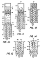
- Figures 10, 11 and 12 illustrate another embodiment in which the body of the syringe has been replaced by a vial 50 closed at one of its ends.
- the second piston which no longer has a raison d' scope, has been eliminated.
- This ampoule is divided into two chambers 51 and 52 of which the first 51 contains a powder or a liquid 53 and an inert gas 54 and the second of which contains a liquid 55 intended to be mixed with the powder 53.
- the two chambers are separated by an internal piston 14 provided with a valve 15, which will be described in more detail below.
- the open end of the bulb 50 is closed by a closure member 56 comprising a substantially cylindrical closure plug 57, the diameter of which is at least equal to the diameter of the section of the bulb 50 near its open end, a shutter 58 housed inside a central bore formed in the plug 57 and a capsule 59 integral with or produced in one piece with the shutter 58.
- the shutter 55 made in one piece with the capsule 59 comprises a thread 60 which cooperates with a complementary thread 61 formed at the base of the central bore of the plug 57 and screwed fully into this bore so that its frusto-conical end section 62 is in abutment against the conical seat 63 constituting the upper end of said central bore of the plug 57.
- a flow duct 64 ending substantially in the center of the needle-holder end 65 of the capsule 59, originates along the periphery of the frustoconical end section 62.
- the internal piston 14 comprises a substantially cylindrical body 66, preferably made of an elastomer, and which is provided with a central recess arranged to allow the positioning of the valve 15 and of the spring members 67.
- the valve 15 is substantially identical to that described with reference to FIGS. 1 to 4 and consists of a plate 68 of circular shape, of a frustoconical element 69 and of a cylindrical section 70 which provides the connection between the plate 68 and the frustoconical element 69.
- An internal conduit 71 allows the liquid 55 to flow towards the chamber 51 when the valve 15 is open.
- Fig. 10 shows the storage position in which the valve 15 and the closure member 56 are closed.
- the device functions substantially like the systems provided with an external piston described above.
- the operator exerts pressure on the bottom 72 of the bulb, by pressing for example with the thumb on this bottom and holding the assembly by the fins 73 of the capsule 59, he pushes the bulb 50 with respect to the capsule 59 and with respect to the plug 57.
- This has the effect of creating an increase in pressure in the two chambers 51 and 52, of opening the valve 15 and of allowing the flow of the liquid 55 in the direction of arrows G.
- the internal piston 14 is coupled to the closure member 56.
- the body 66 of the internal piston 14 has an annular rim 74 intended to engage on a frontal projection 75 formed along the inner end of the plug 57.
- FIG. 11 illustrates an intermediate position in which the inner piston is adopting its final position.
- the shutter 58 has been unscrewed by rotation of the capsule 59 relative to the bulb 50, which has the effect of freeing the passage between the frustoconical end section 62 and the conical seat 63, passage communicating with the conduit 71 formed in the valve 15.
- a simple pressure on the bottom 72 of the bulb makes it possible to inject the prepared mixture into the chamber 51.
- This mixing syringe design is particularly advantageous because of the simplicity of its production and the small number of parts necessary for its manufacture. This results in an extremely competitive cost as well as the possibility of fully automating assembly and filling.
- the shutter member used in the embodiment according to FIGS. 10 to 12 can have various variants illustrated in particular by FIGS. 13, 14 and 15, 16.
- the shutter member of FIGS. 13 and 14 comprises a plug 80 whose enlarged base 81 is screwed inside a capsule 82.
- the plug 80 is provided with a central bore 83 in which is engaged a shutter 84 whose side wall is equipped with an axial groove 85 communicating with the central duct 86 of a needle holder tip 87.
- the upper end of the shutter 84 has a frustoconical shape which cooperates with a conical seat constituting the upper end of the central bore 83 of the plug 80 to seal the 'bulb and prevent the flow of liquid contained in the lower chamber through the axial groove 85.
- Figures 15 and 16 show another variant comprising as previously a plug 90, the narrowed base 81 is provided with a thread for screwing or unscrewing this plug on the base 91 of a shutter 92 housed in a central bore of the plug 90.
- the base 91 of the shutter 92 is integral with a block 93 produced in one piece with the capsule 94 and the needle-holder tip 95.
- the shutter 92 comprises a frustoconical upper section 96 whose peripheral surface is , in the storage position illustrated in fig. 15, bearing against the walls of a conical seat which constitutes the upper part of the central bore of the plug 90.
- a relative movement of the shutter 92 relative to the plug 90 makes it possible to free up a passage sufficient to ensure the flow of the mixture towards the central conduit 97 passing through the block 93 and the needle holder 95.
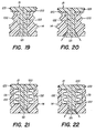
- FIGS. 17 and 18 illustrate a first embodiment of an internal piston 14 provided with a valve 15 and spring members 100 made in one piece with the body of the piston 14.
- These spring members are constituted by an annular structure whose cross section axial has an accordion pleated shape and which is made of a flexible elastomer material capable of being crushed in the direction of the double arrow I.
- the valve 15 has an upper part 101 in contact with the chamber containing the liquid.
- An enlarged rim 102 adjacent to the part 101 makes it possible to couple the valve to the body of the piston 100.
- a cylindrical section 103 of reduced section provides the connection between the upper part 101 and the lower frustoconical element 105 oriented towards the chamber containing the powder topped of a compressible gas.
- the radial channel 106 communicating with the axial duct 107 is closed by an annular bead 108 formed along the wall of the conical seat 109 in which is housed the frustoconical element 105 of the valve 15.
- An annular bead 110 in the shape of a point on which a shoulder 111 of the cylindrical section 103 of the valve 15 is supported, ensures the sealing of the central cavity 112 by preventing a rise of liquid along the walls of the conical seat 109.
- FIGS 19 and 20 illustrate another embodiment of the inner piston 14 and its valve 15.
- the valve 15 consists of an upper plate 120 connected to a frustoconical end piece 121 by a cylindrical section 122.
- a seal 123 is mounted in a peripheral groove of the plate 120.
- FIGS. 21 and 22 differs from that in FIGS. 19 and 20 in that the spring members 131 are constituted by a metallic spiral spring housed in a cavity 132 formed inside the body of the piston 14.
- the other elements such as the upper plate 120 of the valve 15, the frustoconical end piece 121 and the cylindrical connecting section 122 as well as the seal 123 are identical to the corresponding elements of the device according to FIGS. 19 and 20.
- the syringes illustrated in FIGS. 23 to 26 include an internal plunger provided with powerful retaining members, but which, as will be demonstrated below, have no character bothersome at the time of injection.
- the syringe body 10 is divided into two chambers 141 and 142, the first of which 141 contains a liquid 143 surmounted by an expanded gas 144, and the second of which 142 preferably contains a powder 145.
- the internal piston 14 includes a valve 15 movable axially inside a central bore formed in the body of the piston, and urged towards its closed position by a spring 146.
- the body of the syringe is closed on one side by an external piston 22 and on the other side by a closure member 147 comprising a stopper 148 disposed inside the body of the syringe and a shutter 149 screwed into a bore of the stopper 148.
- the inner face of the stopper 148 has recesses 150, 151, 152 of complementary shapes to those of the protrusions 153, 154 and 155 formed at the base of the internal piston 14.
- the internal piston 14 comprises powerful retaining members, located along its periphery, these members being in the form of elastic beads bearing on the smooth wall of the body of the syringe.
- the valve opens and at least part of the liquid 143 can flow to the chamber 145 without back pressure which allows a complete and rapid discharge.
- the valve closes under the effect of the thrust exerted by the spring 146.
- a new cycle can be started.
- the internal piston 14 is entirely driven back to the bottom of the syringe body and the protrusions 153, 154 and 155 have engaged in the complementary recesses. shutters 150, 151 and 152.
- a rotation of the shutter 149 integral with the capsule 156 makes it possible to clear a passage 157 between the plug 149 and the shutter 148 and to ensure the evacuation of the mixture, the shutter 15 being blocked. in the open position when the internal piston and the closure member are coupled (see fig. 26).
- the syringe ampoule illustrated in FIGS. 27 and 28 comprises an ampoule 50 identical to that of FIGS. 10 to 12 and provided with a closure member similar to the closure member 56.
- the internal piston 14 divides the ampoule in two chambers 161 and 162 of which the first contains powder and the other a liquid and an initially expanded gas.
- the device works much like the previous one.
- the push on the bottom of the bulb causes compression of the gas, the valve 15 remaining closed.
- the expansion of the gas after release of the pressure, causes the valve to open and the liquid to pass (see fig. 29).
- the valve 15 consists of a frustoconical block 163 forming an upper plate 164 and a lower plate 165.
- a flexible central stop 166 is supported on the lower plate 165, and an annular stop 167 is supported on a shoulder 168 formed between the plate upper and lower tray. These stops block the valve in the closed position in FIGS. 27 and 28 and are crushed when the valve is open, as shown in FIG. 29.
- the internal piston is pushed back into a position in which the retaining members present no discomfort during injection (see fig. 28).
- the latter system in particular is advantageous in that the number of parts which compose it is particularly reduced.
Landscapes
- Health & Medical Sciences (AREA)
- Vascular Medicine (AREA)
- Engineering & Computer Science (AREA)
- Anesthesiology (AREA)
- Biomedical Technology (AREA)
- Heart & Thoracic Surgery (AREA)
- Hematology (AREA)
- Life Sciences & Earth Sciences (AREA)
- Animal Behavior & Ethology (AREA)
- General Health & Medical Sciences (AREA)
- Public Health (AREA)
- Veterinary Medicine (AREA)
- Infusion, Injection, And Reservoir Apparatuses (AREA)
Applications Claiming Priority (2)
| Application Number | Priority Date | Filing Date | Title |
|---|---|---|---|
| CH8200139 | 1982-12-27 | ||
| WOPCT/CH82/00139 | 1982-12-27 |
Publications (1)
| Publication Number | Publication Date |
|---|---|
| EP0112574A1 true EP0112574A1 (fr) | 1984-07-04 |
Family
ID=4539342
Family Applications (1)
| Application Number | Title | Priority Date | Filing Date |
|---|---|---|---|
| EP83113098A Withdrawn EP0112574A1 (fr) | 1982-12-27 | 1983-12-24 | Seringue préremplie à double compartiment |
Country Status (2)
| Country | Link |
|---|---|
| EP (1) | EP0112574A1 (ja) |
| JP (1) | JPS59155264A (ja) |
Cited By (42)
| Publication number | Priority date | Publication date | Assignee | Title |
|---|---|---|---|---|
| US4596561A (en) * | 1983-05-04 | 1986-06-24 | Meditec S.A. | Prefilled single-dose syringe |
| EP0397977A2 (de) * | 1989-05-17 | 1990-11-22 | Arzneimittel GmbH Apotheker Vetter & Co. Ravensburg | Spritze für medizinische Zwecke |
| EP0737485A1 (en) * | 1993-12-28 | 1996-10-16 | HIGASHIKAWA, Tetsuro | Syringe |
| EP0768901A1 (en) * | 1994-06-30 | 1997-04-23 | Science Incorporated | Fluid delivery apparatus |
| WO1997041909A1 (en) * | 1996-05-03 | 1997-11-13 | Nordway Limited | Vial for use as syringe accessory |
| WO1998001174A1 (fr) * | 1996-07-05 | 1998-01-15 | Debiotech S.A. | Seringue a chambre double permettant le melange de deux produits avant leur injection |
| WO1998046136A1 (fr) * | 1997-04-15 | 1998-10-22 | Debiotech S.A. | Seringue a compartiments multiples |
| EP0974373A1 (en) * | 1998-07-20 | 2000-01-26 | Jaime Luis Szapiro Melamed | Syringe with two variable volume chambers for containing and administering mixtures of products provided separately |
| FR2784034A1 (fr) * | 1998-10-01 | 2000-04-07 | Marc Brunel | Dispositif d'injection a usage unique destine a etre pre-rempli |
| GB2376048A (en) * | 2001-03-31 | 2002-12-04 | David William Armfield | An intermediate piston for dispensing sealant from a tube in sequence |
| US6641561B1 (en) | 2000-10-10 | 2003-11-04 | Meridian Medical Technologies, Inc. | Drug delivery device |
| FR2839892A1 (fr) * | 2002-05-27 | 2003-11-28 | Mb Innovation | Dispositif d'injection a usage unique destine a etre pre-rempli |
| WO2004037326A2 (en) * | 2002-10-23 | 2004-05-06 | Boston Scientific Limited | Mixing and delivery medical syringe system for therapeutic compositions |
| US6770052B2 (en) | 2000-10-10 | 2004-08-03 | Meridian Medical Technologies, Inc. | Wet/dry automatic injector assembly |
| WO2007058866A1 (en) * | 2005-11-16 | 2007-05-24 | Paul Mario Diperna | Novel enhanced device and technique for mixing and dispensing a preserved agent |
| EP1797920A1 (de) * | 2005-12-15 | 2007-06-20 | Dentaco Dentalindustrie- und Marketing GmbH | Vorrichtung zur Aufnahme und zum Austragen einer fliessfähigen Substanz |
| US7556614B2 (en) | 2000-10-10 | 2009-07-07 | Meridian Medical Technologies, Inc. | Separation assembly for drug delivery device |
| US7608055B2 (en) | 2000-10-10 | 2009-10-27 | Meridian Medical Technologies, Inc. | Flow-path inserts for wet/dry automatic injectors |
| US7757370B2 (en) | 2000-10-10 | 2010-07-20 | Meridian Medical Technologies, Inc. | Methods of forming a needle and hub assembly for automatic injectors |
| WO2011133672A3 (en) * | 2010-04-20 | 2012-01-05 | West Pharmaceutical Services, Inc. | Automatic injection syringe assembly with integrated, fillable medicine container and method of filling an injection syringe assembly |
| USD657876S1 (en) | 2010-02-02 | 2012-04-17 | 3M Innovative Properties Company | Dental capsule |
| WO2012110057A1 (en) | 2011-02-15 | 2012-08-23 | Chemisches Institut Schaefer Ag | Cefuroxime safety kit |
| US8323237B2 (en) | 2006-06-21 | 2012-12-04 | Novo Nordisk Healthcare Ag | One-hand operated drug mixing and expelling device |
| US8556848B2 (en) | 2008-01-17 | 2013-10-15 | Becton, Dickinson & Company | Valve for mixing of substances |
| WO2013163598A3 (en) * | 2012-04-27 | 2013-12-19 | Glucago, Llc | Reconstitution device |
| WO2014099846A1 (en) | 2012-12-20 | 2014-06-26 | Merck Sharp & Dohme Corp. | Dual chamber mixing syringes and methods of using same |
| US20150011975A1 (en) * | 2012-02-22 | 2015-01-08 | Consort Medical Plc | Syringe assembly |
| US8992469B2 (en) | 2012-06-26 | 2015-03-31 | Glucago Llc | Reconstitution device |
| EP2853311A1 (en) * | 2013-09-30 | 2015-04-01 | Shofu Inc. | Two-component mixing container including piston using spring engagement |
| US9125995B2 (en) | 2012-12-05 | 2015-09-08 | Glucago Llc | Reconstitution devices |
| US9149581B2 (en) | 2009-03-09 | 2015-10-06 | Glucago Llc | Compact device for rapidly mixing and delivering substances to a patient |
| WO2015159013A1 (fr) * | 2014-04-16 | 2015-10-22 | Aptar France Sas | Distributeur de produit fluide. |
| EP2432528A4 (en) * | 2009-05-22 | 2017-09-13 | Michael P. Connair | Steroid delivery system |
| US9844796B2 (en) | 2005-10-14 | 2017-12-19 | 3M Innovative Properties Company | Plunger and plunger assembly for a cartridge, system for storing a substance, and method of filling and sealing a substance in a delivery system |
| EP3183020A4 (en) * | 2014-08-18 | 2018-05-02 | Windgap Medical, Inc. | Portable drug mixing and delivery device and associated methods |
| US10030771B2 (en) | 2013-07-29 | 2018-07-24 | Terumo Kabushiki Kaisha | Gasket insertion method for mounting gasket inside outer cylinder of syringe, and gasket for mounting |
| AU2018203250B2 (en) * | 2017-05-17 | 2019-01-17 | Heraeus Medical Gmbh | Bone cement applicator with hollow cylinder on delivery plunger |
| US20200139048A1 (en) * | 2013-03-15 | 2020-05-07 | Windgap Medical, Inc. | Portable drug mixing and delivery device and associated methods |
| US10695505B2 (en) | 2014-10-21 | 2020-06-30 | Sulzer Mixpac Ag | Dual-chamber syringe |
| US11185391B2 (en) | 2016-09-21 | 2021-11-30 | 3M Innovative Properties Company | Mixer assembly and device for dispensing a dental material |
| US11590285B2 (en) * | 2011-11-07 | 2023-02-28 | Battelle Memorial Institute | Processes for delivery of viscous drug therapies |
| WO2024042068A1 (en) * | 2022-08-22 | 2024-02-29 | Kevin Abbott | Device for fluid-dispensing vessel |
Families Citing this family (9)
| Publication number | Priority date | Publication date | Assignee | Title |
|---|---|---|---|---|
| JPH01500165A (ja) * | 1986-07-11 | 1989-01-26 | アルツナイミツテル ゲ−エムベ−ハ− アポテ−カ フエツタ− ウント コンパニ ラ−ヴエンスブルク | 医療用注射器 |
| JPH03276856A (ja) * | 1990-03-27 | 1991-12-09 | Nissan Motor Co Ltd | 車両の旋回挙動制御装置 |
| JP2762711B2 (ja) * | 1990-07-02 | 1998-06-04 | 日産自動車株式会社 | 車両の制動挙動補償装置 |
| JP2623927B2 (ja) * | 1990-07-05 | 1997-06-25 | 日産自動車株式会社 | 車両の旋回挙動制御装置 |
| JP2583367B2 (ja) * | 1991-07-22 | 1997-02-19 | 日産自動車株式会社 | 制動力制御装置 |
| AU2002332808C1 (en) * | 2002-09-03 | 2008-11-13 | Meridian Medical Technologies, Inc. | Drug delivery device |
| JP4902096B2 (ja) * | 2003-07-10 | 2012-03-21 | 株式会社根本杏林堂 | 薬液シリンジ |
| JP2005185747A (ja) * | 2003-12-26 | 2005-07-14 | Sumitomo Rubber Ind Ltd | ガスケット及びプレフィルドシリンジ |
| CN112295093B (zh) * | 2020-09-30 | 2022-12-06 | 广州迈普再生医学科技股份有限公司 | 一种医用胶电动喷涂装置 |
Citations (9)
| Publication number | Priority date | Publication date | Assignee | Title |
|---|---|---|---|---|
| FR458199A (fr) * | 1913-05-21 | 1913-10-04 | Pierre Antoine Gentile | Seringue pour usages médicaux avec piston à clapet |
| US2567001A (en) * | 1950-02-06 | 1951-09-04 | Thomas E Watson | Hypodermic syringe |
| US3076456A (en) * | 1960-03-07 | 1963-02-05 | Elsie B Hunt | Hypodermic syringe |
| US3380451A (en) * | 1965-06-14 | 1968-04-30 | Robert E. Porter | Two compartment syringe |
| FR1574830A (ja) * | 1967-03-04 | 1969-07-18 | ||
| FR1598878A (ja) * | 1968-12-27 | 1970-07-06 | ||
| DE1909794A1 (de) * | 1969-02-27 | 1970-09-17 | Ehrhardt Soehne Fa | Spritzampulle fuer zwei Komponenten |
| FR2082128A5 (en) * | 1970-03-04 | 1971-12-10 | Idees | Syringe - for preserving and injecting medicaments |
| CH541481A (fr) * | 1971-08-12 | 1973-09-15 | Lacroix Michel | Distributeur de produit fluide |
-
1983
- 1983-12-24 EP EP83113098A patent/EP0112574A1/fr not_active Withdrawn
- 1983-12-27 JP JP58252270A patent/JPS59155264A/ja active Pending
Patent Citations (9)
| Publication number | Priority date | Publication date | Assignee | Title |
|---|---|---|---|---|
| FR458199A (fr) * | 1913-05-21 | 1913-10-04 | Pierre Antoine Gentile | Seringue pour usages médicaux avec piston à clapet |
| US2567001A (en) * | 1950-02-06 | 1951-09-04 | Thomas E Watson | Hypodermic syringe |
| US3076456A (en) * | 1960-03-07 | 1963-02-05 | Elsie B Hunt | Hypodermic syringe |
| US3380451A (en) * | 1965-06-14 | 1968-04-30 | Robert E. Porter | Two compartment syringe |
| FR1574830A (ja) * | 1967-03-04 | 1969-07-18 | ||
| FR1598878A (ja) * | 1968-12-27 | 1970-07-06 | ||
| DE1909794A1 (de) * | 1969-02-27 | 1970-09-17 | Ehrhardt Soehne Fa | Spritzampulle fuer zwei Komponenten |
| FR2082128A5 (en) * | 1970-03-04 | 1971-12-10 | Idees | Syringe - for preserving and injecting medicaments |
| CH541481A (fr) * | 1971-08-12 | 1973-09-15 | Lacroix Michel | Distributeur de produit fluide |
Cited By (83)
| Publication number | Priority date | Publication date | Assignee | Title |
|---|---|---|---|---|
| US4596561A (en) * | 1983-05-04 | 1986-06-24 | Meditec S.A. | Prefilled single-dose syringe |
| EP0397977A2 (de) * | 1989-05-17 | 1990-11-22 | Arzneimittel GmbH Apotheker Vetter & Co. Ravensburg | Spritze für medizinische Zwecke |
| EP0397977A3 (de) * | 1989-05-17 | 1991-03-20 | Arzneimittel GmbH Apotheker Vetter & Co. Ravensburg | Spritze für medizinische Zwecke |
| EP0737485A1 (en) * | 1993-12-28 | 1996-10-16 | HIGASHIKAWA, Tetsuro | Syringe |
| US5830193A (en) * | 1993-12-28 | 1998-11-03 | Higashikawa; Tetsuro | Syringe |
| EP0737485A4 (en) * | 1993-12-28 | 1998-02-04 | Tetsuro Higashikawa | SYRINGE |
| EP0768901A4 (en) * | 1994-06-30 | 1998-09-30 | Science Inc | LIQUID SUPPLY APPARATUS |
| EP0768901A1 (en) * | 1994-06-30 | 1997-04-23 | Science Incorporated | Fluid delivery apparatus |
| US6080131A (en) * | 1996-05-03 | 2000-06-27 | Nordway Limited | Vial for use as syringe accessory |
| WO1997041909A1 (en) * | 1996-05-03 | 1997-11-13 | Nordway Limited | Vial for use as syringe accessory |
| WO1998001174A1 (fr) * | 1996-07-05 | 1998-01-15 | Debiotech S.A. | Seringue a chambre double permettant le melange de deux produits avant leur injection |
| WO1998046136A1 (fr) * | 1997-04-15 | 1998-10-22 | Debiotech S.A. | Seringue a compartiments multiples |
| EP0974373A1 (en) * | 1998-07-20 | 2000-01-26 | Jaime Luis Szapiro Melamed | Syringe with two variable volume chambers for containing and administering mixtures of products provided separately |
| FR2784034A1 (fr) * | 1998-10-01 | 2000-04-07 | Marc Brunel | Dispositif d'injection a usage unique destine a etre pre-rempli |
| WO2000020057A1 (fr) * | 1998-10-01 | 2000-04-13 | Sanofi-Synthelabo | Dispositif d'injection a usage unique destine a etre pre-rempli |
| US6432090B1 (en) | 1998-10-01 | 2002-08-13 | Sanofi-Synthelabo | Disposable injection device designed to be pre-filled |
| US8568367B2 (en) | 2000-10-10 | 2013-10-29 | Meridian Medical Technologies, Inc. | Needle assemblies for wet/dry automatic injectors |
| US6641561B1 (en) | 2000-10-10 | 2003-11-04 | Meridian Medical Technologies, Inc. | Drug delivery device |
| US8187220B2 (en) | 2000-10-10 | 2012-05-29 | Meridian Medical Technologies, Inc. | Seal structures for wet/dry automatic injectors |
| US8506526B2 (en) | 2000-10-10 | 2013-08-13 | Meridian Medical Technologies, Inc. | Seal structures for wet/dry automatic injectors |
| US6770052B2 (en) | 2000-10-10 | 2004-08-03 | Meridian Medical Technologies, Inc. | Wet/dry automatic injector assembly |
| US7608055B2 (en) | 2000-10-10 | 2009-10-27 | Meridian Medical Technologies, Inc. | Flow-path inserts for wet/dry automatic injectors |
| US7757370B2 (en) | 2000-10-10 | 2010-07-20 | Meridian Medical Technologies, Inc. | Methods of forming a needle and hub assembly for automatic injectors |
| US7749190B2 (en) | 2000-10-10 | 2010-07-06 | Meridan Medical Technologies, Inc. | Seal structures for wet/dry automatic injectors |
| US7621887B2 (en) | 2000-10-10 | 2009-11-24 | Meridian Medical Technologies, Inc. | Wet/dry automatic injector assembly |
| US7556614B2 (en) | 2000-10-10 | 2009-07-07 | Meridian Medical Technologies, Inc. | Separation assembly for drug delivery device |
| GB2376048A (en) * | 2001-03-31 | 2002-12-04 | David William Armfield | An intermediate piston for dispensing sealant from a tube in sequence |
| GB2376048B (en) * | 2001-03-31 | 2004-11-10 | David William Armfield | Pistons |
| EP1393763A1 (en) * | 2001-07-03 | 2004-03-03 | Meridian Medical Technologies, Inc. | Drug delivery device |
| FR2839892A1 (fr) * | 2002-05-27 | 2003-11-28 | Mb Innovation | Dispositif d'injection a usage unique destine a etre pre-rempli |
| AU2003255605C1 (en) * | 2002-05-27 | 2009-08-27 | Mb Innovation | Disposable injection device designed to be pre-filled |
| AU2003255605B2 (en) * | 2002-05-27 | 2008-11-13 | Mb Innovation | Disposable injection device designed to be pre-filled |
| WO2003100424A3 (fr) * | 2002-05-27 | 2004-04-15 | Mb Innovation | Dispositif d'injection a usage unique destine a etre pre-rempli |
| US7883490B2 (en) | 2002-10-23 | 2011-02-08 | Boston Scientific Scimed, Inc. | Mixing and delivery of therapeutic compositions |
| WO2004037326A3 (en) * | 2002-10-23 | 2004-12-23 | Boston Scient Ltd | Mixing and delivery medical syringe system for therapeutic compositions |
| WO2004037326A2 (en) * | 2002-10-23 | 2004-05-06 | Boston Scientific Limited | Mixing and delivery medical syringe system for therapeutic compositions |
| US10279935B2 (en) | 2005-10-14 | 2019-05-07 | 3M Innovative Properties Company | Plunger and plunger assembly for a cartridge, system for storing a substance, and method of filing and sealing a substance in a delivery system |
| US9844796B2 (en) | 2005-10-14 | 2017-12-19 | 3M Innovative Properties Company | Plunger and plunger assembly for a cartridge, system for storing a substance, and method of filling and sealing a substance in a delivery system |
| WO2007058866A1 (en) * | 2005-11-16 | 2007-05-24 | Paul Mario Diperna | Novel enhanced device and technique for mixing and dispensing a preserved agent |
| US8197448B2 (en) | 2005-12-15 | 2012-06-12 | Sulzer Mixpac Ag | Device for retaining and dispensing a free-flowing substance |
| EP1797920A1 (de) * | 2005-12-15 | 2007-06-20 | Dentaco Dentalindustrie- und Marketing GmbH | Vorrichtung zur Aufnahme und zum Austragen einer fliessfähigen Substanz |
| CN101007192B (zh) * | 2005-12-15 | 2011-10-05 | 苏尔寿米克斯帕有限公司 | 用于保持和分配自由流动物质的装置 |
| US7927312B2 (en) | 2005-12-15 | 2011-04-19 | Sulzer Mixpac Ag | Device for retaining and dispensing a free-flowing substance |
| US8323237B2 (en) | 2006-06-21 | 2012-12-04 | Novo Nordisk Healthcare Ag | One-hand operated drug mixing and expelling device |
| EP2231232A4 (en) * | 2008-01-17 | 2015-07-29 | Becton Dickinson Co | VALVE FOR MIXING SUBSTANCES |
| US8556848B2 (en) | 2008-01-17 | 2013-10-15 | Becton, Dickinson & Company | Valve for mixing of substances |
| US9149581B2 (en) | 2009-03-09 | 2015-10-06 | Glucago Llc | Compact device for rapidly mixing and delivering substances to a patient |
| EP2432528A4 (en) * | 2009-05-22 | 2017-09-13 | Michael P. Connair | Steroid delivery system |
| USD657876S1 (en) | 2010-02-02 | 2012-04-17 | 3M Innovative Properties Company | Dental capsule |
| USD658763S1 (en) | 2010-02-02 | 2012-05-01 | 3M Innovative Properties Company | Dental capsule |
| WO2011133672A3 (en) * | 2010-04-20 | 2012-01-05 | West Pharmaceutical Services, Inc. | Automatic injection syringe assembly with integrated, fillable medicine container and method of filling an injection syringe assembly |
| US9259536B2 (en) | 2010-04-20 | 2016-02-16 | West Pharmaceutical Services, Inc. | Automatic injection syringe assembly with integrated, fillable medicine container and method of filling an injection syringe assembly |
| WO2012110471A1 (en) | 2011-02-15 | 2012-08-23 | Chemisches Institut Schaefer Ag | Cefuroxime safety delivery system |
| WO2012110057A1 (en) | 2011-02-15 | 2012-08-23 | Chemisches Institut Schaefer Ag | Cefuroxime safety kit |
| US11590285B2 (en) * | 2011-11-07 | 2023-02-28 | Battelle Memorial Institute | Processes for delivery of viscous drug therapies |
| US20150011975A1 (en) * | 2012-02-22 | 2015-01-08 | Consort Medical Plc | Syringe assembly |
| US9962492B2 (en) * | 2012-02-22 | 2018-05-08 | Consort Medical Plc | Syringe assembly |
| AU2013223804B2 (en) * | 2012-02-22 | 2017-07-13 | Consort Medical Plc | Improved syringe assembly |
| WO2013163598A3 (en) * | 2012-04-27 | 2013-12-19 | Glucago, Llc | Reconstitution device |
| US8992469B2 (en) | 2012-06-26 | 2015-03-31 | Glucago Llc | Reconstitution device |
| US9125995B2 (en) | 2012-12-05 | 2015-09-08 | Glucago Llc | Reconstitution devices |
| US20150343153A1 (en) * | 2012-12-20 | 2015-12-03 | Christopher J. Granelli | Dual chamber mixing syringes and methods of using same |
| US9872962B2 (en) | 2012-12-20 | 2018-01-23 | Merck Sharp & Dohme Corp. | Dual chamber mixing syringes and methods of using same |
| WO2014099846A1 (en) | 2012-12-20 | 2014-06-26 | Merck Sharp & Dohme Corp. | Dual chamber mixing syringes and methods of using same |
| EP2934636A4 (en) * | 2012-12-20 | 2016-08-17 | Merck Sharp & Dohme | DOUBLE CHAMBER MIXING SYRINGES AND METHODS OF USE THEREOF |
| US20200139048A1 (en) * | 2013-03-15 | 2020-05-07 | Windgap Medical, Inc. | Portable drug mixing and delivery device and associated methods |
| US10030771B2 (en) | 2013-07-29 | 2018-07-24 | Terumo Kabushiki Kaisha | Gasket insertion method for mounting gasket inside outer cylinder of syringe, and gasket for mounting |
| CN104512634A (zh) * | 2013-09-30 | 2015-04-15 | 株式会社松风 | 具有利用弹簧卡合的活塞的双成分混合容器 |
| CN104512634B (zh) * | 2013-09-30 | 2017-11-14 | 株式会社松风 | 具有利用弹簧卡合的活塞的双成分混合容器 |
| EP2853311A1 (en) * | 2013-09-30 | 2015-04-01 | Shofu Inc. | Two-component mixing container including piston using spring engagement |
| US9162199B2 (en) | 2013-09-30 | 2015-10-20 | Shofu Inc. | Two-component mixing container including piston using spring engagement |
| US10076762B2 (en) | 2014-04-16 | 2018-09-18 | Aptar France Sas | Fluid product dispenser |
| WO2015159013A1 (fr) * | 2014-04-16 | 2015-10-22 | Aptar France Sas | Distributeur de produit fluide. |
| CN106170345B (zh) * | 2014-04-16 | 2018-11-16 | 阿普塔尔法国简易股份公司 | 流体产品分配器 |
| FR3020052A1 (fr) * | 2014-04-16 | 2015-10-23 | Aptar France Sas | Distributeur de produit fluide. |
| CN106170345A (zh) * | 2014-04-16 | 2016-11-30 | 阿普塔尔法国简易股份公司 | 流体产品分配器 |
| EP3183015A4 (en) * | 2014-08-18 | 2018-05-02 | Windgap Medical, Inc. | Portable drug mixing and delivery device and associated methods |
| EP3183020A4 (en) * | 2014-08-18 | 2018-05-02 | Windgap Medical, Inc. | Portable drug mixing and delivery device and associated methods |
| US10695505B2 (en) | 2014-10-21 | 2020-06-30 | Sulzer Mixpac Ag | Dual-chamber syringe |
| US11185391B2 (en) | 2016-09-21 | 2021-11-30 | 3M Innovative Properties Company | Mixer assembly and device for dispensing a dental material |
| AU2018203250B2 (en) * | 2017-05-17 | 2019-01-17 | Heraeus Medical Gmbh | Bone cement applicator with hollow cylinder on delivery plunger |
| US10987147B2 (en) | 2017-05-17 | 2021-04-27 | Heraeus Medical Gmbh | Bone cement applicator with hollow cylinder on delivery plunger |
| WO2024042068A1 (en) * | 2022-08-22 | 2024-02-29 | Kevin Abbott | Device for fluid-dispensing vessel |
Also Published As
| Publication number | Publication date |
|---|---|
| JPS59155264A (ja) | 1984-09-04 |
Similar Documents
| Publication | Publication Date | Title |
|---|---|---|
| EP0112574A1 (fr) | Seringue préremplie à double compartiment | |
| EP0462255B1 (fr) | Flacon de stockage et de transfert a double compartiment | |
| EP0721573B1 (fr) | Dispositif doseur destine a delivrer des doses unitaires constantes | |
| EP0453555B1 (fr) | Flacon de stockage contenant un composant d'une solution medicamenteuse | |
| WO1987006141A1 (fr) | Dispositif de conditionnement de substances liquides ou liquides et solides | |
| EP0551782B1 (fr) | Valve doseuse utilisable en position inversée | |
| EP1115361B1 (fr) | Dispositif de connexion entre un recipient et un contenant et ensemble pret a l'emploi comprenant un tel dispositif | |
| EP1015335B1 (fr) | Recipient distributeur multichambre pour le stockage d'au moins deux substances. | |
| FR2836129A1 (fr) | Dispositif de connexion entre un recipient et un contenant et ensemble pret a l'emploi comprenant un tel dispositif | |
| FR2503565A1 (fr) | Ensemble a corps unique et deux compartiments pour medicaments | |
| EP1507565B1 (fr) | Dispositif d injection a usage unique destine a etre pre-rem pli | |
| FR2790948A1 (fr) | Dispositif de transfert bidirectionnel d'un liquide entre un flacon et une capsule | |
| EP0111796A1 (fr) | Ampoule-seringue | |
| WO1998001174A1 (fr) | Seringue a chambre double permettant le melange de deux produits avant leur injection | |
| FR2900344A1 (fr) | Dispositif d'injection avec aiguille retractable | |
| FR2749833A1 (fr) | Recipient de distribution de produits | |
| EP0069686A1 (fr) | Dispositif permettant le mélange à terme de deux ou plusieurs composants | |
| FR2477403A1 (fr) | Ensemble a aiguilles multiples de prise d'echantillons comportant un clapet anti-refoulement | |
| CA1319131C (fr) | Appareil distributeur de substances liquides | |
| WO1998049994A1 (fr) | Dispositif de mise en solution d'un produit lyophilise, contenu dans une cartouche a usage unique utilisee dans un dispositif d'injection sans aiguille | |
| FR2667050A1 (fr) | Dispositif pour projeter sous forme pulverisee ou pulsee une dose definie de liquide ou produit visqueux, et notamment un medicament, et procede pour maintenir ce dispositif etanche. | |
| WO1991000749A1 (fr) | Seringue et aiguille d'injection a usage unique | |
| FR2853830A1 (fr) | Capuchon de transfert a moyen d'etancheite | |
| FR2667049A1 (fr) | Flacon double corps. | |
| BE738453A (en) | Syringe assembly |
Legal Events
| Date | Code | Title | Description |
|---|---|---|---|
| PUAI | Public reference made under article 153(3) epc to a published international application that has entered the european phase |
Free format text: ORIGINAL CODE: 0009012 |
|
| AK | Designated contracting states |
Designated state(s): AT BE CH DE FR GB IT LI LU NL SE |
|
| 17P | Request for examination filed |
Effective date: 19841228 |
|
| 17Q | First examination report despatched |
Effective date: 19860122 |
|
| STAA | Information on the status of an ep patent application or granted ep patent |
Free format text: STATUS: THE APPLICATION IS DEEMED TO BE WITHDRAWN |
|
| 18D | Application deemed to be withdrawn |
Effective date: 19860603 |
|
| RIN1 | Information on inventor provided before grant (corrected) |
Inventor name: MEYER, GABRIEL Inventor name: HOWALD, ERNST |