EP0110835A2 - Cylindre de serrure à verrouillage électromagnétique intégré - Google Patents
Cylindre de serrure à verrouillage électromagnétique intégré Download PDFInfo
- Publication number
- EP0110835A2 EP0110835A2 EP83810551A EP83810551A EP0110835A2 EP 0110835 A2 EP0110835 A2 EP 0110835A2 EP 83810551 A EP83810551 A EP 83810551A EP 83810551 A EP83810551 A EP 83810551A EP 0110835 A2 EP0110835 A2 EP 0110835A2
- Authority
- EP
- European Patent Office
- Prior art keywords
- lock cylinder
- locking
- lock
- rotor
- stator
- Prior art date
- Legal status (The legal status is an assumption and is not a legal conclusion. Google has not performed a legal analysis and makes no representation as to the accuracy of the status listed.)
- Granted
Links
Images

Classifications
-
- E—FIXED CONSTRUCTIONS
- E05—LOCKS; KEYS; WINDOW OR DOOR FITTINGS; SAFES
- E05B—LOCKS; ACCESSORIES THEREFOR; HANDCUFFS
- E05B47/00—Operating or controlling locks or other fastening devices by electric or magnetic means
- E05B47/02—Movement of the bolt by electromagnetic means; Adaptation of locks, latches, or parts thereof, for movement of the bolt by electromagnetic means
-
- E—FIXED CONSTRUCTIONS
- E05—LOCKS; KEYS; WINDOW OR DOOR FITTINGS; SAFES
- E05B—LOCKS; ACCESSORIES THEREFOR; HANDCUFFS
- E05B47/00—Operating or controlling locks or other fastening devices by electric or magnetic means
- E05B47/06—Controlling mechanically-operated bolts by electro-magnetically-operated detents
- E05B47/0611—Cylinder locks with electromagnetic control
- E05B47/0619—Cylinder locks with electromagnetic control by blocking the rotor
- E05B47/0623—Cylinder locks with electromagnetic control by blocking the rotor axially, i.e. with an axially engaging blocking element
-
- E—FIXED CONSTRUCTIONS
- E05—LOCKS; KEYS; WINDOW OR DOOR FITTINGS; SAFES
- E05B—LOCKS; ACCESSORIES THEREFOR; HANDCUFFS
- E05B27/00—Cylinder locks or other locks with tumbler pins or balls that are set by pushing the key in
-
- E—FIXED CONSTRUCTIONS
- E05—LOCKS; KEYS; WINDOW OR DOOR FITTINGS; SAFES
- E05B—LOCKS; ACCESSORIES THEREFOR; HANDCUFFS
- E05B47/00—Operating or controlling locks or other fastening devices by electric or magnetic means
- E05B47/0001—Operating or controlling locks or other fastening devices by electric or magnetic means with electric actuators; Constructional features thereof
- E05B47/0002—Operating or controlling locks or other fastening devices by electric or magnetic means with electric actuators; Constructional features thereof with electromagnets
- E05B47/0003—Operating or controlling locks or other fastening devices by electric or magnetic means with electric actuators; Constructional features thereof with electromagnets having a movable core
- E05B47/0004—Operating or controlling locks or other fastening devices by electric or magnetic means with electric actuators; Constructional features thereof with electromagnets having a movable core said core being linearly movable
-
- Y—GENERAL TAGGING OF NEW TECHNOLOGICAL DEVELOPMENTS; GENERAL TAGGING OF CROSS-SECTIONAL TECHNOLOGIES SPANNING OVER SEVERAL SECTIONS OF THE IPC; TECHNICAL SUBJECTS COVERED BY FORMER USPC CROSS-REFERENCE ART COLLECTIONS [XRACs] AND DIGESTS
- Y10—TECHNICAL SUBJECTS COVERED BY FORMER USPC
- Y10S—TECHNICAL SUBJECTS COVERED BY FORMER USPC CROSS-REFERENCE ART COLLECTIONS [XRACs] AND DIGESTS
- Y10S70/00—Locks
- Y10S70/62—Cylinder plug stop
-
- Y—GENERAL TAGGING OF NEW TECHNOLOGICAL DEVELOPMENTS; GENERAL TAGGING OF CROSS-SECTIONAL TECHNOLOGIES SPANNING OVER SEVERAL SECTIONS OF THE IPC; TECHNICAL SUBJECTS COVERED BY FORMER USPC CROSS-REFERENCE ART COLLECTIONS [XRACs] AND DIGESTS
- Y10—TECHNICAL SUBJECTS COVERED BY FORMER USPC
- Y10T—TECHNICAL SUBJECTS COVERED BY FORMER US CLASSIFICATION
- Y10T70/00—Locks
- Y10T70/70—Operating mechanism
- Y10T70/7051—Using a powered device [e.g., motor]
- Y10T70/7062—Electrical type [e.g., solenoid]
- Y10T70/7124—Retracted electrically only
-
- Y—GENERAL TAGGING OF NEW TECHNOLOGICAL DEVELOPMENTS; GENERAL TAGGING OF CROSS-SECTIONAL TECHNOLOGIES SPANNING OVER SEVERAL SECTIONS OF THE IPC; TECHNICAL SUBJECTS COVERED BY FORMER USPC CROSS-REFERENCE ART COLLECTIONS [XRACs] AND DIGESTS
- Y10—TECHNICAL SUBJECTS COVERED BY FORMER USPC
- Y10T—TECHNICAL SUBJECTS COVERED BY FORMER US CLASSIFICATION
- Y10T70/00—Locks
- Y10T70/70—Operating mechanism
- Y10T70/7441—Key
- Y10T70/7486—Single key
- Y10T70/7508—Tumbler type
- Y10T70/7559—Cylinder type
- Y10T70/7667—Operating elements, parts and adjuncts
- Y10T70/7706—Operating connections
- Y10T70/7712—Rollbacks
-
- Y—GENERAL TAGGING OF NEW TECHNOLOGICAL DEVELOPMENTS; GENERAL TAGGING OF CROSS-SECTIONAL TECHNOLOGIES SPANNING OVER SEVERAL SECTIONS OF THE IPC; TECHNICAL SUBJECTS COVERED BY FORMER USPC CROSS-REFERENCE ART COLLECTIONS [XRACs] AND DIGESTS
- Y10—TECHNICAL SUBJECTS COVERED BY FORMER USPC
- Y10T—TECHNICAL SUBJECTS COVERED BY FORMER US CLASSIFICATION
- Y10T70/00—Locks
- Y10T70/70—Operating mechanism
- Y10T70/7441—Key
- Y10T70/7915—Tampering prevention or attack defeating
- Y10T70/7932—Anti-pick
- Y10T70/7944—Guard tumbler
Definitions
- the invention relates to a security lock cylinder with mechanical tumbler and an electromagnetic tumbler arranged in the cylinder, the mechanical tumblers being unlocked by the associated key, but the electromagnetic tumbler by an external actuation.
- Combinations are known in which a mechanical interlock, which is actuated by mechanical means, interacts with a mechanical interlock, which is actuated by electromagnetic means. It is customary to use the mechanical means to open a lock on site, for example by means of a door knob, door latch, but also a key, etc., and to actuate the same lock from a remote location using the electromagnetic means.
- the independence of the location of the operating location for manipulating electromagnetic means allows, for example, central monitoring of partially remote closings, this monitoring, for example, from time to time dependent fully automatically, by intervention of an operator, also by imposing condition specifications, etc.
- the mechanical means for actuating the lock which is a door lock, are rotary knobs arranged on the door for pushing a bolt.
- the electromagnetic means actuate an additional bolt which, depending on the position, blocks or releases the main bolt.
- a security cylinder is associated with the actuation or triggering of the electromagnetically actuated additional bolt, and this in turn has a query device.
- the electromagnetic part is housed in the door frame, as is the security cylinder that triggers the electromagnetics.
- the security cylinder actuates the electromagnetic lock exclusively, with the help of a specially crafted serrated key, which contains the information for the reader arranged in the back of the key.
- the electromagnetic triggering can also take place disjunctively, that is to say in a key OR central form.
- an additional bolt that can be actuated by electromagnetic means blocks the main bolt.
- the additional mechanical locking system which is manipulated via a security cylinder using a key, is housed together with the electromagnetic means in the door lock case, i.e. not separately in the door and frame.
- the lock bolt is not blocked in the front bolt part, but in the rear bolt part.
- Blocking a bolt acting, for example, between the door and the door frame, either by a device in the door frame or a device in the door, requires a special configuration of the lock.
- intervening changes in the mechanical part of the lock even preferably, require the replacement of an existing lock with one that is intended for the additional electromagnetic lock, or with such is already provided in terms of production.
- FIG. 1 now shows the side of a lock cylinder 10 carrying the locking parts, that is, based on the spatial representation of FIG. 5, the rear part of the lock cylinder protruding into the lock mechanism.
- the cylinder sleeve 7 delimiting the lock cylinder has an outer circumference which corresponds to the standardized dimensions.
- a lock cylinder according to the present invention can be used in a conventionally equipped lock; either when replacing, for example, if an existing lock is to be additionally lockable, or when creating new locks in which the additional electromagnetic lock is provided.
- the usual lock systems that are widespread everywhere can therefore be used without modification.
- the stator 5 is arranged within the cylinder sleeve 7. this has radial bores for the mechanical tumblers to be actuated with the key.
- These mechanical tumblers are only indicated by the tumbler planes 4, the tumbler planes, for example 45 ° inclined to the key main plane, being designated 4a and 4a ', the plane 90 ° inclined 4b and 4b', and furthermore the tumbler plane coinciding with the key master plane 4c '.
- the rotor 3 with the key channel end 1 and a locking part 28 is visible. This locking part 28 comes into engagement with a locking ring 37, also shown, attached to the rotor 3, for example, when the armature 21 is brought into one of two intended positions or positions by the magnetic effect.
- the armature 21 is part of the entire electromagnetic bolt 20, which is in a in the stator 5th axially extending groove 6 is housed.
- the groove for receiving the magnetic bar is covered by the cylinder sleeve 7 and pressed at the same time, so that the magnetic bar 20 is largely secured against rotation and displacement.
- the position of the magnetic bar in the stator groove can be secured by various precautions, of which, for example, the partial flange 44 shown in FIG. 5 on the magnetic bar 20, or the carrier plate 42 for the electrical leads 45 for actuating the magnetic winding of the bar, or both elements together should be mentioned as appropriate.
- a fixed connection 38 between the rotor 3 and the locking ring 37 has the effect that a link 40, only indicated here, for example with a rounded locking edge 48, can be moved together with the rotor 3 by turning the key on the locking part 28 in a defined position.
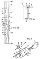
- the detailed version of the magnetic bar is shown in Fig. 2.
- a housing 25 preferably adapted to the shape of the groove, but in the simplest embodiment cylindrical, which encloses the electrical and mechanical locking parts.
- the coil body 24 carrying the magnetic coil 23 is inserted and fastened in the bolt housing.
- the soft iron armature 21 running through the inner part of the coil 23 carries a locking washer 27 attached in approximately one third of its length, which is dimensioned so large that it acts as a longitudinal movement limitation against the stop 29 arranged at the end of the housing.
- a compression coil spring 26 acting between the coil body 24 and the locking washer 27 brings the armature 21 into a defined position with respect to the housing 25 and thus also with respect to the rotor 3 of the lock cylinder.
- the magnetic field generated by the excited winding pulls the armature 21 against the force of the compression coil spring 26 as far as the armature stop 22, while at the same time a clearance 21 'in the longitudinal direction is released for the dumbbell-shaped locking part 28 which is freely movable on the extension of the active armature part.
- This forward and backward movement possibility of the locking part 28 is used to inhibit or release the rotary movement of the rotor by engagement of the locking part in the locking ring 37 fixedly connected to the rotor 3.
- the locking part 28 specified here for example, in the form of a dumbbell, engages with a disk end in a locking ring groove shown below with groove walls designed to form sliding blocks, the entire locking part being able to be moved back and forth along its rotational or longitudinal axis by rotating the locking ring.
- the (other) disk end 28 ′′ and the inside of the housing 25 shown here in a cylindrical shape serve as the sliding seat 47.
- the “barbell handle” serves as the connecting part 28 ′ co-forming disc 28 "and the other disc in engagement with the backdrop of the reciprocating locking part 28 finds the necessary space.
- FIG. 3 The interaction of the lock cylinder 10 with the magnetic bolt 20 or the interaction of the magnetic bolt 20 with the rotor 3 can be seen in FIG. 3.
- the magnetic bar 20 shown in FIG. 2 is fastened in the groove 6 incorporated in the stator 5.
- the front part of the lock cylinder shown is provided with an input flange 31 for the key channel 1. This page is for the key from accessible from outside.
- the opposite side that is to say inside the lock, carries the electrically actuable blocking with the locking ring 37, the link 40 and the link play 42 and the locking part 28.
- the whole together also forms the rotor end 39 with the connection 38 between the rotor and locking ring. You can still see some of the tumblers 4, which are shown in FIG. 1 with their tumbler levels.
- the locking part 28 protrudes into the backdrop 40, and the rotor 3 cannot be rotated about its axis after unlocking the mechanical tumblers by means of the key belonging to the lock cylinder because of the backdrop locking; this despite an attempt to actuate the correct key, i.e. the key assigned to the security cylinder.
- the excitation power to be applied can be reduced by holding the armature 21 in the immediate vicinity of the armature stop 22 in a defined rest or neutral state in order to keep the air gap to be overcome by the flooding as small as possible. This is done by special training of the scenery 40, as shown for example in Figure 4b at 0 ° +. This makes it possible to unlock the lock cylinder with a relatively low current and still a sufficiently large holding force. This is an essential aspect in the specified versions in small signal technology.
- FIGS. 4a and 4b show in detail the locking with the locking ring 37 and the locking part 28.
- FIG. 4a it is shown again in a schematic representation how the locking part 28, the locking ring 37 and the magnet armature 21 interact in principle.
- the locking ring 37 is rotatably movable and firmly connected to the cylinder rotor 3 and driven by this in a clockwise or counterclockwise direction.
- the blocking part 28 is arranged in close contact with the setting 40 of the locking ring 37, a type of (setting) groove; it moves through the locking ring 37 or its backdrop 40 driven back and forth in the rotational axis direction of the locking ring. In its free mobility, the locking part 28 is only affected by the position of the magnet armature 21.
- the blocking part can translate freely within the scope that is thereby freed.
- the locking part 28 in the example shown is pressed against a wall part of the link 40 by the force of the helical compression spring 26.
- Different states can be created with an ON / OFF function.
- a development of the link 40 of the locking ring 37 in connection with the locking part 28 is in an exemplary embodiment. 4b shown.
- the blocking part 28 is arranged in the neutral or rest position at 0 °.
- a rotation in the + 180 ° direction causes the lock to close and a rotation in the 180 direction opens the lock.
- the formation of the backdrop in this example enables the same control process when opening as when closing, which can also be seen in the symmetrical design. If the magnet 20 is now de-energized, the blocking part 28 is pressed by the force of the spring 26 against the link wall lying on the right in the drawing. Turning the locking ring 37 in either direction would cause blocking at one of the locking edges 48 R after about 60 °.
- the locking part 28 can be moved into the locked position, that is to say without the aid of a spring force. Only an excitation pulse of a certain length of time and at a certain time releases the further rotation of the rotor.
- phase R from 0 - 60 ° as reading phase and phase D from 60 0 - 100 ° as decision phase. In phase R there would be a radio if the magnet was defective tional rotation prevented from the outset, since a decision is no longer possible if the magnet is defective.
- a key to a lock cylinder of this type should not only be mechanically recognizable for this by means of a tumbler bolt, but also electrically.
- the key By inserting specially ferromagnetic or magnetized parts into specially provided holes in the key, the key is able to "send" its own code.
- a reading device i.e. a receiver, reads and recognizes this code and evaluates it accordingly.
- the electronics to be used for this can be accommodated in the door or in the frame, for example.
- FIG. 5 The entire arrangement of the magnetic latch 20, lock cylinder 10, rotor end 39 and the corresponding key is shown in a spatial representation in FIG. 5.
- only one lock cylinder 10 of a lock can be seen from a lock.
- a further lock cylinder facing the lock cylinder 10 shown must be arranged. Both are able to operate the common lock and both have mechanical tumblers assigned to a corresponding key.
- the carrier plate 42 for the electrical feed lines 45 which is arranged at one end of the magnetic bar 20, is mounted outside the cylinder sleeve 7 only slightly overhanging in its radius. As already mentioned, it can also be used to secure the position of the magnetic bolt 20 in the stator 5. It is even more expedient for the partial flange 44 to be fitted onto the rotor end 39 or for the housing shape of the magnetic latch housing 25 to be adapted to an axial groove 6 running in the stator 5.
Priority Applications (1)
| Application Number | Priority Date | Filing Date | Title |
|---|---|---|---|
| AT83810551T ATE33869T1 (de) | 1982-11-26 | 1983-11-24 | Schlosszylinder mit integrierter elektromagnetischer verriegelung. |
Applications Claiming Priority (2)
| Application Number | Priority Date | Filing Date | Title |
|---|---|---|---|
| CH690382 | 1982-11-26 | ||
| CH6903/82 | 1982-11-26 |
Publications (3)
| Publication Number | Publication Date |
|---|---|
| EP0110835A2 true EP0110835A2 (fr) | 1984-06-13 |
| EP0110835A3 EP0110835A3 (en) | 1984-10-10 |
| EP0110835B1 EP0110835B1 (fr) | 1988-04-27 |
Family
ID=4316865
Family Applications (1)
| Application Number | Title | Priority Date | Filing Date |
|---|---|---|---|
| EP83810551A Expired EP0110835B1 (fr) | 1982-11-26 | 1983-11-24 | Cylindre de serrure à verrouillage électromagnétique intégré |
Country Status (8)
| Country | Link |
|---|---|
| US (1) | US4761976A (fr) |
| EP (1) | EP0110835B1 (fr) |
| JP (1) | JPS59109674A (fr) |
| KR (1) | KR890003022B1 (fr) |
| AT (1) | ATE33869T1 (fr) |
| AU (1) | AU566903B2 (fr) |
| DE (1) | DE3376437D1 (fr) |
| ES (1) | ES527777A0 (fr) |
Cited By (11)
| Publication number | Priority date | Publication date | Assignee | Title |
|---|---|---|---|---|
| DE3630597A1 (de) * | 1985-10-24 | 1987-05-14 | Bauer Kaba Ag | Vorrichtung zur elektromagnetischen verriegelung an einem schliesszylinder fuer ein mechanisch/elektronisches schliess-system |
| DE3632904A1 (de) * | 1985-12-19 | 1987-06-25 | Bauer Kaba Ag | Schliesseinrichtung fuer ein mechanisch/elektronisches schliess-system |
| EP0281507A2 (fr) * | 1987-03-05 | 1988-09-07 | IKON AKTIENGESELLSCHAFT Präzisionstechnik | Serrure cylindrique double |
| DE3727566A1 (de) * | 1987-08-19 | 1989-03-02 | Bks Gmbh | Schliesszylinder mit elektromagnetisch betaetigbarem sperrelement |
| US5092147A (en) * | 1985-09-12 | 1992-03-03 | Nissan Motor Co., Ltd. | Steering lock |
| EP0882858A2 (fr) * | 1994-10-25 | 1998-12-09 | WILKA SCHLIESSTECHNIK GmbH | Serrure cylindrique à goupille électromagnétique |
| EP1022416A1 (fr) * | 1999-01-19 | 2000-07-26 | Aug. Winkhaus GmbH & Co. KG | Dispositif de blocage à actionnement électromagnétique |
| EP1366255A1 (fr) * | 2001-02-13 | 2003-12-03 | Videx, Inc. | Systeme de verrouillage electronique |
| DE102005001067A1 (de) * | 2005-01-07 | 2006-07-20 | Aug. Winkhaus Gmbh & Co. Kg | Schließzylinder |
| WO2021027282A1 (fr) * | 2019-08-13 | 2021-02-18 | 上海杉脉电子科技发展有限公司 | Verrou intelligent miniature doté d'une fonction anti-effraction |
| DE102005004774B4 (de) | 2004-02-06 | 2021-08-12 | Continental Teves Ag & Co. Ohg | Verfahren zur Prüfung einer hydraulischen Kraftfahrzeugbremsanlage und hydraulische Kraftfahrzeugbremsanlage |
Families Citing this family (20)
| Publication number | Priority date | Publication date | Assignee | Title |
|---|---|---|---|---|
| US4848115A (en) * | 1986-03-21 | 1989-07-18 | Emhart Industries, Inc. | Electronic locking system and key therefor |
| US4712398A (en) * | 1986-03-21 | 1987-12-15 | Emhart Industries, Inc. | Electronic locking system and key therefor |
| IL81451A (en) * | 1987-02-02 | 1990-03-19 | Eldad Ben-Asher | Electronic lock |
| CH671800A5 (fr) * | 1987-02-09 | 1989-09-29 | Berchtold Ag | |
| FR2631067B1 (fr) * | 1988-05-04 | 1991-02-08 | Neiman Sa | Verrou a rotor debrayable |
| US4909053A (en) * | 1988-05-17 | 1990-03-20 | Liberty Telephone Communications, Inc. | High security door locking device |
| GB2255368B (en) * | 1991-05-03 | 1994-09-28 | Yale Security Prod Ltd | Electro-mechanical lock devices |
| US5582050A (en) * | 1991-12-19 | 1996-12-10 | Assa Ab | Cylinder lock-key-combination, a key therefor and a method of producing the key from a key blank |
| US5771722A (en) * | 1993-11-12 | 1998-06-30 | Kaba High Security Locks Corporation | Dual control mode lock system |
| US5423198A (en) * | 1993-11-12 | 1995-06-13 | Kaba High Security Locks, Inc. | Dual control mode lock |
| US5636880A (en) * | 1995-10-11 | 1997-06-10 | Milocon Corporation | Electronic lock |
| US6209367B1 (en) | 1997-06-06 | 2001-04-03 | Richard G. Hyatt, Jr. | Electronic cam assembly |
| US6588243B1 (en) | 1997-06-06 | 2003-07-08 | Richard G. Hyatt, Jr. | Electronic cam assembly |
| DE10020038A1 (de) * | 2000-04-22 | 2001-10-25 | Winkhaus Fa August | Elektromagnetisch aktivierbarer Sperrmechanismus |
| TW501648U (en) * | 2002-02-08 | 2002-09-01 | Acer Peripherals Inc | Self-locking hinge apparatus with a single stable state |
| ES2577327T3 (es) * | 2006-09-14 | 2016-07-14 | The Knox Company | Conjunto electrónico de cerradura y llave |
| NZ579688A (en) * | 2007-04-27 | 2011-12-22 | Assa Abloy Ab | A modular lock cylinder having a free-turning function between the cylinder core and the tailpiece |
| US8276415B2 (en) | 2009-03-20 | 2012-10-02 | Knox Associates | Holding coil for electronic lock |
| US9041510B2 (en) | 2012-12-05 | 2015-05-26 | Knox Associates, Inc. | Capacitive data transfer in an electronic lock and key assembly |
| USD881677S1 (en) | 2017-04-27 | 2020-04-21 | Knox Associates, Inc. | Electronic key |
Citations (5)
| Publication number | Priority date | Publication date | Assignee | Title |
|---|---|---|---|---|
| US2475220A (en) * | 1946-10-09 | 1949-07-05 | Ray Chaulk | Electric key lock |
| DE2325566A1 (de) * | 1973-05-19 | 1974-12-05 | Zeiss Ikon Ag | Mit magnetischen mitteln arbeitendes schloss, insbesondere zylinderschloss, und hiermit ausgestattete verschlussanlage |
| FR2428130A1 (fr) * | 1978-06-06 | 1980-01-04 | Neiman Sa | Dispositif de verrouillage et de deverrouillage du barillet d'une serrure cylindrique |
| DD156727A5 (de) * | 1980-03-07 | 1982-09-15 | Sodex Magister | Zylinderschloss |
| WO1982004459A1 (fr) * | 1981-06-17 | 1982-12-23 | Kleinhaeny Arno | Barillet de serrure a verrouillage electromagnetique integre |
Family Cites Families (11)
| Publication number | Priority date | Publication date | Assignee | Title |
|---|---|---|---|---|
| US288512A (en) * | 1883-11-13 | Le grand terry | ||
| US874438A (en) * | 1907-06-08 | 1907-12-24 | Samuel Berlowitz | Lock. |
| US1010727A (en) * | 1911-04-07 | 1911-12-05 | Philip Corbin | Lock. |
| US1464315A (en) * | 1921-09-20 | 1923-08-07 | Cowles And Company C | Locking handle for vehicle doors |
| US1695518A (en) * | 1927-10-10 | 1928-12-18 | Glenn W Watson | Electric lock |
| US1832108A (en) * | 1929-12-23 | 1931-11-17 | Falk Morris | Removable plug for pin tumbler locks |
| US3599454A (en) * | 1969-12-31 | 1971-08-17 | Sargent & Co | Key reader and identifier system |
| US3788110A (en) * | 1970-12-09 | 1974-01-29 | Showa Sargent Ltd | Pin-tumbler lock cylinder |
| US3939679A (en) * | 1973-06-19 | 1976-02-24 | Precision Thin Film Corporation | Safety system |
| AU6557274A (en) * | 1974-02-13 | 1975-08-14 | Engineering Desing & Dev Pty L | Locking apparatus |
| NO792077L (no) * | 1978-06-27 | 1979-12-28 | Marlok Inc | Doerstyreenhet. |
-
1983
- 1983-11-22 AU AU21588/83A patent/AU566903B2/en not_active Ceased
- 1983-11-24 AT AT83810551T patent/ATE33869T1/de not_active IP Right Cessation
- 1983-11-24 DE DE8383810551T patent/DE3376437D1/de not_active Expired
- 1983-11-24 ES ES527777A patent/ES527777A0/es active Granted
- 1983-11-24 EP EP83810551A patent/EP0110835B1/fr not_active Expired
- 1983-11-25 JP JP58223040A patent/JPS59109674A/ja active Pending
- 1983-11-26 KR KR1019830005602A patent/KR890003022B1/ko not_active IP Right Cessation
- 1983-11-28 US US06/555,332 patent/US4761976A/en not_active Expired - Fee Related
Patent Citations (5)
| Publication number | Priority date | Publication date | Assignee | Title |
|---|---|---|---|---|
| US2475220A (en) * | 1946-10-09 | 1949-07-05 | Ray Chaulk | Electric key lock |
| DE2325566A1 (de) * | 1973-05-19 | 1974-12-05 | Zeiss Ikon Ag | Mit magnetischen mitteln arbeitendes schloss, insbesondere zylinderschloss, und hiermit ausgestattete verschlussanlage |
| FR2428130A1 (fr) * | 1978-06-06 | 1980-01-04 | Neiman Sa | Dispositif de verrouillage et de deverrouillage du barillet d'une serrure cylindrique |
| DD156727A5 (de) * | 1980-03-07 | 1982-09-15 | Sodex Magister | Zylinderschloss |
| WO1982004459A1 (fr) * | 1981-06-17 | 1982-12-23 | Kleinhaeny Arno | Barillet de serrure a verrouillage electromagnetique integre |
Non-Patent Citations (1)
| Title |
|---|
| "Baubeschlag Magazin" 10/1980, s.158 * |
Cited By (16)
| Publication number | Priority date | Publication date | Assignee | Title |
|---|---|---|---|---|
| US5092147A (en) * | 1985-09-12 | 1992-03-03 | Nissan Motor Co., Ltd. | Steering lock |
| DE3630597A1 (de) * | 1985-10-24 | 1987-05-14 | Bauer Kaba Ag | Vorrichtung zur elektromagnetischen verriegelung an einem schliesszylinder fuer ein mechanisch/elektronisches schliess-system |
| FR2595397A1 (fr) * | 1985-10-24 | 1987-09-11 | Bauer Kaba Ag | Dispositif de verrouillage electromagnetique sur un barillet pour un systeme de verrouillage mecanique/electronique |
| US4730471A (en) * | 1985-10-24 | 1988-03-15 | Bauer Kaba Ag | Apparatus for electromagnetic locking on a lock cylinder for a mechanical/electronic locking system |
| DE3632904A1 (de) * | 1985-12-19 | 1987-06-25 | Bauer Kaba Ag | Schliesseinrichtung fuer ein mechanisch/elektronisches schliess-system |
| EP0281507A2 (fr) * | 1987-03-05 | 1988-09-07 | IKON AKTIENGESELLSCHAFT Präzisionstechnik | Serrure cylindrique double |
| EP0281507A3 (en) * | 1987-03-05 | 1988-11-17 | Zeiss Ikon Ag | Double-cylinder lock |
| DE3727566A1 (de) * | 1987-08-19 | 1989-03-02 | Bks Gmbh | Schliesszylinder mit elektromagnetisch betaetigbarem sperrelement |
| EP0882858A2 (fr) * | 1994-10-25 | 1998-12-09 | WILKA SCHLIESSTECHNIK GmbH | Serrure cylindrique à goupille électromagnétique |
| EP0882858A3 (fr) * | 1994-10-25 | 1999-08-18 | WILKA SCHLIESSTECHNIK GmbH | Serrure cylindrique à goupille électromagnétique |
| EP1022416A1 (fr) * | 1999-01-19 | 2000-07-26 | Aug. Winkhaus GmbH & Co. KG | Dispositif de blocage à actionnement électromagnétique |
| EP1366255A1 (fr) * | 2001-02-13 | 2003-12-03 | Videx, Inc. | Systeme de verrouillage electronique |
| EP1366255A4 (fr) * | 2001-02-13 | 2010-04-14 | Videx Inc | Systeme de verrouillage electronique |
| DE102005004774B4 (de) | 2004-02-06 | 2021-08-12 | Continental Teves Ag & Co. Ohg | Verfahren zur Prüfung einer hydraulischen Kraftfahrzeugbremsanlage und hydraulische Kraftfahrzeugbremsanlage |
| DE102005001067A1 (de) * | 2005-01-07 | 2006-07-20 | Aug. Winkhaus Gmbh & Co. Kg | Schließzylinder |
| WO2021027282A1 (fr) * | 2019-08-13 | 2021-02-18 | 上海杉脉电子科技发展有限公司 | Verrou intelligent miniature doté d'une fonction anti-effraction |
Also Published As
| Publication number | Publication date |
|---|---|
| ES8500374A1 (es) | 1984-11-01 |
| AU566903B2 (en) | 1987-11-05 |
| EP0110835B1 (fr) | 1988-04-27 |
| AU2158883A (en) | 1984-05-31 |
| JPS59109674A (ja) | 1984-06-25 |
| ES527777A0 (es) | 1984-11-01 |
| DE3376437D1 (en) | 1988-06-01 |
| KR890003022B1 (ko) | 1989-08-18 |
| EP0110835A3 (en) | 1984-10-10 |
| US4761976A (en) | 1988-08-09 |
| ATE33869T1 (de) | 1988-05-15 |
| KR840006841A (ko) | 1984-12-03 |
Similar Documents
| Publication | Publication Date | Title |
|---|---|---|
| EP0110835B1 (fr) | Cylindre de serrure à verrouillage électromagnétique intégré | |
| WO1982004459A1 (fr) | Barillet de serrure a verrouillage electromagnetique integre | |
| DE19861400B4 (de) | Schließzylinder | |
| DE3632904C2 (fr) | ||
| DE2123168B2 (de) | Magnetische spperr- und steuervorrichtung | |
| DE3048222A1 (de) | "schloss" | |
| DE10303220B3 (de) | Schließzylinder | |
| WO2004057137A1 (fr) | Dispositif de verrouillage | |
| EP1065335B1 (fr) | Système de verrouillage électromécanique | |
| DE10055361C2 (de) | Vorrichtung mit einer Lenkungsverriegelung sowie mit einem Zündanlassschalter, die bei Anwesenheit eines Identifikationsgebers von einer Handhabe steuerbar sind | |
| DE102009005322B4 (de) | Elektronische Möbelschließeinheit | |
| EP0304760B1 (fr) | Système de fermeture être composé d'une serrure et plusieurs clés | |
| DE2522301C3 (de) | Elektromagnetische Zentralverriegelungsvorrichtung für die Türen eines Kraftfahrzeuges | |
| EP0668422A1 (fr) | Mécanisme de blocage pour serrure | |
| EP1135284A1 (fr) | Systeme de fermeture, notamment pour automobiles | |
| DE3707201A1 (de) | Doppelschliesszylinder | |
| DE3105390A1 (de) | Zylinderschloss | |
| EP1170443B1 (fr) | Combinaison d'une entraînement électromoteur pour serrure et d'un système d'alarme | |
| DE3639111C1 (en) | Stop-and-block lock | |
| EP0710969B1 (fr) | Dispositif verrouillable entraîné manuellement pour appareils de commutation blindés | |
| WO2002057575A1 (fr) | Dispositif de fermeture a commande electronique | |
| DE19614576C2 (de) | Schloß | |
| EP0943762A2 (fr) | Dispositif de verrouillage / deverrouillage avec une codage mécanique et électrique | |
| DE19812276C1 (de) | Sicherheitsschloß | |
| DE10015802C1 (de) | Schloß-Schlüssel-System |
Legal Events
| Date | Code | Title | Description |
|---|---|---|---|
| PUAI | Public reference made under article 153(3) epc to a published international application that has entered the european phase |
Free format text: ORIGINAL CODE: 0009012 |
|
| AK | Designated contracting states |
Designated state(s): AT BE CH DE FR GB IT LI LU NL SE |
|
| PUAL | Search report despatched |
Free format text: ORIGINAL CODE: 0009013 |
|
| AK | Designated contracting states |
Designated state(s): AT BE CH DE FR GB IT LI LU NL SE |
|
| 17P | Request for examination filed |
Effective date: 19850328 |
|
| 17Q | First examination report despatched |
Effective date: 19860513 |
|
| ITF | It: translation for a ep patent filed |
Owner name: DE DOMINICIS & MAYER S.R.L. |
|
| GRAA | (expected) grant |
Free format text: ORIGINAL CODE: 0009210 |
|
| AK | Designated contracting states |
Kind code of ref document: B1 Designated state(s): AT BE CH DE FR GB IT LI LU NL SE |
|
| REF | Corresponds to: |
Ref document number: 33869 Country of ref document: AT Date of ref document: 19880515 Kind code of ref document: T |
|
| GBT | Gb: translation of ep patent filed (gb section 77(6)(a)/1977) | ||
| REF | Corresponds to: |
Ref document number: 3376437 Country of ref document: DE Date of ref document: 19880601 |
|
| ET | Fr: translation filed | ||
| PG25 | Lapsed in a contracting state [announced via postgrant information from national office to epo] |
Ref country code: LU Free format text: LAPSE BECAUSE OF NON-PAYMENT OF DUE FEES Effective date: 19881130 |
|
| PLBE | No opposition filed within time limit |
Free format text: ORIGINAL CODE: 0009261 |
|
| STAA | Information on the status of an ep patent application or granted ep patent |
Free format text: STATUS: NO OPPOSITION FILED WITHIN TIME LIMIT |
|
| 26N | No opposition filed | ||
| PGFP | Annual fee paid to national office [announced via postgrant information from national office to epo] |
Ref country code: GB Payment date: 19890930 Year of fee payment: 7 |
|
| PGFP | Annual fee paid to national office [announced via postgrant information from national office to epo] |
Ref country code: LU Payment date: 19891019 Year of fee payment: 7 |
|
| PGFP | Annual fee paid to national office [announced via postgrant information from national office to epo] |
Ref country code: DE Payment date: 19891027 Year of fee payment: 7 |
|
| PGFP | Annual fee paid to national office [announced via postgrant information from national office to epo] |
Ref country code: BE Payment date: 19891108 Year of fee payment: 7 |
|
| PGFP | Annual fee paid to national office [announced via postgrant information from national office to epo] |
Ref country code: SE Payment date: 19891129 Year of fee payment: 7 |
|
| ITTA | It: last paid annual fee | ||
| PGFP | Annual fee paid to national office [announced via postgrant information from national office to epo] |
Ref country code: CH Payment date: 19900220 Year of fee payment: 7 |
|
| PGFP | Annual fee paid to national office [announced via postgrant information from national office to epo] |
Ref country code: AT Payment date: 19900920 Year of fee payment: 8 |
|
| PG25 | Lapsed in a contracting state [announced via postgrant information from national office to epo] |
Ref country code: GB Effective date: 19901124 |
|
| PG25 | Lapsed in a contracting state [announced via postgrant information from national office to epo] |
Ref country code: SE Effective date: 19901125 |
|
| PG25 | Lapsed in a contracting state [announced via postgrant information from national office to epo] |
Ref country code: LI Effective date: 19901130 Ref country code: CH Effective date: 19901130 Ref country code: BE Effective date: 19901130 |
|
| BERE | Be: lapsed |
Owner name: BAUER KABA A.G. Effective date: 19901130 |
|
| GBPC | Gb: european patent ceased through non-payment of renewal fee | ||
| REG | Reference to a national code |
Ref country code: CH Ref legal event code: PL |
|
| PG25 | Lapsed in a contracting state [announced via postgrant information from national office to epo] |
Ref country code: DE Effective date: 19910801 |
|
| PG25 | Lapsed in a contracting state [announced via postgrant information from national office to epo] |
Ref country code: AT Effective date: 19911124 |
|
| PGFP | Annual fee paid to national office [announced via postgrant information from national office to epo] |
Ref country code: FR Payment date: 19911128 Year of fee payment: 9 |
|
| PGFP | Annual fee paid to national office [announced via postgrant information from national office to epo] |
Ref country code: NL Payment date: 19921130 Year of fee payment: 10 |
|
| PG25 | Lapsed in a contracting state [announced via postgrant information from national office to epo] |
Ref country code: FR Effective date: 19930730 |
|
| REG | Reference to a national code |
Ref country code: FR Ref legal event code: ST |
|
| PG25 | Lapsed in a contracting state [announced via postgrant information from national office to epo] |
Ref country code: NL Effective date: 19940601 |
|
| NLV4 | Nl: lapsed or anulled due to non-payment of the annual fee | ||
| EUG | Se: european patent has lapsed |
Ref document number: 83810551.8 Effective date: 19910705 |