EP0110835A2 - Lock cylinder with integrated electromagnetic locking - Google Patents
Lock cylinder with integrated electromagnetic locking Download PDFInfo
- Publication number
- EP0110835A2 EP0110835A2 EP83810551A EP83810551A EP0110835A2 EP 0110835 A2 EP0110835 A2 EP 0110835A2 EP 83810551 A EP83810551 A EP 83810551A EP 83810551 A EP83810551 A EP 83810551A EP 0110835 A2 EP0110835 A2 EP 0110835A2
- Authority
- EP
- European Patent Office
- Prior art keywords
- lock cylinder
- locking
- lock
- rotor
- stator
- Prior art date
- Legal status (The legal status is an assumption and is not a legal conclusion. Google has not performed a legal analysis and makes no representation as to the accuracy of the status listed.)
- Granted
Links
Images

Classifications
-
- E—FIXED CONSTRUCTIONS
- E05—LOCKS; KEYS; WINDOW OR DOOR FITTINGS; SAFES
- E05B—LOCKS; ACCESSORIES THEREFOR; HANDCUFFS
- E05B47/00—Operating or controlling locks or other fastening devices by electric or magnetic means
- E05B47/02—Movement of the bolt by electromagnetic means; Adaptation of locks, latches, or parts thereof, for movement of the bolt by electromagnetic means
-
- E—FIXED CONSTRUCTIONS
- E05—LOCKS; KEYS; WINDOW OR DOOR FITTINGS; SAFES
- E05B—LOCKS; ACCESSORIES THEREFOR; HANDCUFFS
- E05B47/00—Operating or controlling locks or other fastening devices by electric or magnetic means
- E05B47/06—Controlling mechanically-operated bolts by electro-magnetically-operated detents
- E05B47/0611—Cylinder locks with electromagnetic control
- E05B47/0619—Cylinder locks with electromagnetic control by blocking the rotor
- E05B47/0623—Cylinder locks with electromagnetic control by blocking the rotor axially, i.e. with an axially engaging blocking element
-
- E—FIXED CONSTRUCTIONS
- E05—LOCKS; KEYS; WINDOW OR DOOR FITTINGS; SAFES
- E05B—LOCKS; ACCESSORIES THEREFOR; HANDCUFFS
- E05B27/00—Cylinder locks or other locks with tumbler pins or balls that are set by pushing the key in
-
- E—FIXED CONSTRUCTIONS
- E05—LOCKS; KEYS; WINDOW OR DOOR FITTINGS; SAFES
- E05B—LOCKS; ACCESSORIES THEREFOR; HANDCUFFS
- E05B47/00—Operating or controlling locks or other fastening devices by electric or magnetic means
- E05B47/0001—Operating or controlling locks or other fastening devices by electric or magnetic means with electric actuators; Constructional features thereof
- E05B47/0002—Operating or controlling locks or other fastening devices by electric or magnetic means with electric actuators; Constructional features thereof with electromagnets
- E05B47/0003—Operating or controlling locks or other fastening devices by electric or magnetic means with electric actuators; Constructional features thereof with electromagnets having a movable core
- E05B47/0004—Operating or controlling locks or other fastening devices by electric or magnetic means with electric actuators; Constructional features thereof with electromagnets having a movable core said core being linearly movable
-
- Y—GENERAL TAGGING OF NEW TECHNOLOGICAL DEVELOPMENTS; GENERAL TAGGING OF CROSS-SECTIONAL TECHNOLOGIES SPANNING OVER SEVERAL SECTIONS OF THE IPC; TECHNICAL SUBJECTS COVERED BY FORMER USPC CROSS-REFERENCE ART COLLECTIONS [XRACs] AND DIGESTS
- Y10—TECHNICAL SUBJECTS COVERED BY FORMER USPC
- Y10S—TECHNICAL SUBJECTS COVERED BY FORMER USPC CROSS-REFERENCE ART COLLECTIONS [XRACs] AND DIGESTS
- Y10S70/00—Locks
- Y10S70/62—Cylinder plug stop
-
- Y—GENERAL TAGGING OF NEW TECHNOLOGICAL DEVELOPMENTS; GENERAL TAGGING OF CROSS-SECTIONAL TECHNOLOGIES SPANNING OVER SEVERAL SECTIONS OF THE IPC; TECHNICAL SUBJECTS COVERED BY FORMER USPC CROSS-REFERENCE ART COLLECTIONS [XRACs] AND DIGESTS
- Y10—TECHNICAL SUBJECTS COVERED BY FORMER USPC
- Y10T—TECHNICAL SUBJECTS COVERED BY FORMER US CLASSIFICATION
- Y10T70/00—Locks
- Y10T70/70—Operating mechanism
- Y10T70/7051—Using a powered device [e.g., motor]
- Y10T70/7062—Electrical type [e.g., solenoid]
- Y10T70/7124—Retracted electrically only
-
- Y—GENERAL TAGGING OF NEW TECHNOLOGICAL DEVELOPMENTS; GENERAL TAGGING OF CROSS-SECTIONAL TECHNOLOGIES SPANNING OVER SEVERAL SECTIONS OF THE IPC; TECHNICAL SUBJECTS COVERED BY FORMER USPC CROSS-REFERENCE ART COLLECTIONS [XRACs] AND DIGESTS
- Y10—TECHNICAL SUBJECTS COVERED BY FORMER USPC
- Y10T—TECHNICAL SUBJECTS COVERED BY FORMER US CLASSIFICATION
- Y10T70/00—Locks
- Y10T70/70—Operating mechanism
- Y10T70/7441—Key
- Y10T70/7486—Single key
- Y10T70/7508—Tumbler type
- Y10T70/7559—Cylinder type
- Y10T70/7667—Operating elements, parts and adjuncts
- Y10T70/7706—Operating connections
- Y10T70/7712—Rollbacks
-
- Y—GENERAL TAGGING OF NEW TECHNOLOGICAL DEVELOPMENTS; GENERAL TAGGING OF CROSS-SECTIONAL TECHNOLOGIES SPANNING OVER SEVERAL SECTIONS OF THE IPC; TECHNICAL SUBJECTS COVERED BY FORMER USPC CROSS-REFERENCE ART COLLECTIONS [XRACs] AND DIGESTS
- Y10—TECHNICAL SUBJECTS COVERED BY FORMER USPC
- Y10T—TECHNICAL SUBJECTS COVERED BY FORMER US CLASSIFICATION
- Y10T70/00—Locks
- Y10T70/70—Operating mechanism
- Y10T70/7441—Key
- Y10T70/7915—Tampering prevention or attack defeating
- Y10T70/7932—Anti-pick
- Y10T70/7944—Guard tumbler
Definitions
- the invention relates to a security lock cylinder with mechanical tumbler and an electromagnetic tumbler arranged in the cylinder, the mechanical tumblers being unlocked by the associated key, but the electromagnetic tumbler by an external actuation.
- Combinations are known in which a mechanical interlock, which is actuated by mechanical means, interacts with a mechanical interlock, which is actuated by electromagnetic means. It is customary to use the mechanical means to open a lock on site, for example by means of a door knob, door latch, but also a key, etc., and to actuate the same lock from a remote location using the electromagnetic means.
- the independence of the location of the operating location for manipulating electromagnetic means allows, for example, central monitoring of partially remote closings, this monitoring, for example, from time to time dependent fully automatically, by intervention of an operator, also by imposing condition specifications, etc.
- the mechanical means for actuating the lock which is a door lock, are rotary knobs arranged on the door for pushing a bolt.
- the electromagnetic means actuate an additional bolt which, depending on the position, blocks or releases the main bolt.
- a security cylinder is associated with the actuation or triggering of the electromagnetically actuated additional bolt, and this in turn has a query device.
- the electromagnetic part is housed in the door frame, as is the security cylinder that triggers the electromagnetics.
- the security cylinder actuates the electromagnetic lock exclusively, with the help of a specially crafted serrated key, which contains the information for the reader arranged in the back of the key.
- the electromagnetic triggering can also take place disjunctively, that is to say in a key OR central form.
- an additional bolt that can be actuated by electromagnetic means blocks the main bolt.
- the additional mechanical locking system which is manipulated via a security cylinder using a key, is housed together with the electromagnetic means in the door lock case, i.e. not separately in the door and frame.
- the lock bolt is not blocked in the front bolt part, but in the rear bolt part.
- Blocking a bolt acting, for example, between the door and the door frame, either by a device in the door frame or a device in the door, requires a special configuration of the lock.
- intervening changes in the mechanical part of the lock even preferably, require the replacement of an existing lock with one that is intended for the additional electromagnetic lock, or with such is already provided in terms of production.
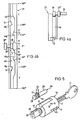
- FIG. 1 now shows the side of a lock cylinder 10 carrying the locking parts, that is, based on the spatial representation of FIG. 5, the rear part of the lock cylinder protruding into the lock mechanism.
- the cylinder sleeve 7 delimiting the lock cylinder has an outer circumference which corresponds to the standardized dimensions.
- a lock cylinder according to the present invention can be used in a conventionally equipped lock; either when replacing, for example, if an existing lock is to be additionally lockable, or when creating new locks in which the additional electromagnetic lock is provided.
- the usual lock systems that are widespread everywhere can therefore be used without modification.
- the stator 5 is arranged within the cylinder sleeve 7. this has radial bores for the mechanical tumblers to be actuated with the key.
- These mechanical tumblers are only indicated by the tumbler planes 4, the tumbler planes, for example 45 ° inclined to the key main plane, being designated 4a and 4a ', the plane 90 ° inclined 4b and 4b', and furthermore the tumbler plane coinciding with the key master plane 4c '.
- the rotor 3 with the key channel end 1 and a locking part 28 is visible. This locking part 28 comes into engagement with a locking ring 37, also shown, attached to the rotor 3, for example, when the armature 21 is brought into one of two intended positions or positions by the magnetic effect.
- the armature 21 is part of the entire electromagnetic bolt 20, which is in a in the stator 5th axially extending groove 6 is housed.
- the groove for receiving the magnetic bar is covered by the cylinder sleeve 7 and pressed at the same time, so that the magnetic bar 20 is largely secured against rotation and displacement.
- the position of the magnetic bar in the stator groove can be secured by various precautions, of which, for example, the partial flange 44 shown in FIG. 5 on the magnetic bar 20, or the carrier plate 42 for the electrical leads 45 for actuating the magnetic winding of the bar, or both elements together should be mentioned as appropriate.
- a fixed connection 38 between the rotor 3 and the locking ring 37 has the effect that a link 40, only indicated here, for example with a rounded locking edge 48, can be moved together with the rotor 3 by turning the key on the locking part 28 in a defined position.
- the detailed version of the magnetic bar is shown in Fig. 2.
- a housing 25 preferably adapted to the shape of the groove, but in the simplest embodiment cylindrical, which encloses the electrical and mechanical locking parts.
- the coil body 24 carrying the magnetic coil 23 is inserted and fastened in the bolt housing.
- the soft iron armature 21 running through the inner part of the coil 23 carries a locking washer 27 attached in approximately one third of its length, which is dimensioned so large that it acts as a longitudinal movement limitation against the stop 29 arranged at the end of the housing.
- a compression coil spring 26 acting between the coil body 24 and the locking washer 27 brings the armature 21 into a defined position with respect to the housing 25 and thus also with respect to the rotor 3 of the lock cylinder.
- the magnetic field generated by the excited winding pulls the armature 21 against the force of the compression coil spring 26 as far as the armature stop 22, while at the same time a clearance 21 'in the longitudinal direction is released for the dumbbell-shaped locking part 28 which is freely movable on the extension of the active armature part.
- This forward and backward movement possibility of the locking part 28 is used to inhibit or release the rotary movement of the rotor by engagement of the locking part in the locking ring 37 fixedly connected to the rotor 3.
- the locking part 28 specified here for example, in the form of a dumbbell, engages with a disk end in a locking ring groove shown below with groove walls designed to form sliding blocks, the entire locking part being able to be moved back and forth along its rotational or longitudinal axis by rotating the locking ring.
- the (other) disk end 28 ′′ and the inside of the housing 25 shown here in a cylindrical shape serve as the sliding seat 47.
- the “barbell handle” serves as the connecting part 28 ′ co-forming disc 28 "and the other disc in engagement with the backdrop of the reciprocating locking part 28 finds the necessary space.
- FIG. 3 The interaction of the lock cylinder 10 with the magnetic bolt 20 or the interaction of the magnetic bolt 20 with the rotor 3 can be seen in FIG. 3.
- the magnetic bar 20 shown in FIG. 2 is fastened in the groove 6 incorporated in the stator 5.
- the front part of the lock cylinder shown is provided with an input flange 31 for the key channel 1. This page is for the key from accessible from outside.
- the opposite side that is to say inside the lock, carries the electrically actuable blocking with the locking ring 37, the link 40 and the link play 42 and the locking part 28.
- the whole together also forms the rotor end 39 with the connection 38 between the rotor and locking ring. You can still see some of the tumblers 4, which are shown in FIG. 1 with their tumbler levels.
- the locking part 28 protrudes into the backdrop 40, and the rotor 3 cannot be rotated about its axis after unlocking the mechanical tumblers by means of the key belonging to the lock cylinder because of the backdrop locking; this despite an attempt to actuate the correct key, i.e. the key assigned to the security cylinder.
- the excitation power to be applied can be reduced by holding the armature 21 in the immediate vicinity of the armature stop 22 in a defined rest or neutral state in order to keep the air gap to be overcome by the flooding as small as possible. This is done by special training of the scenery 40, as shown for example in Figure 4b at 0 ° +. This makes it possible to unlock the lock cylinder with a relatively low current and still a sufficiently large holding force. This is an essential aspect in the specified versions in small signal technology.
- FIGS. 4a and 4b show in detail the locking with the locking ring 37 and the locking part 28.
- FIG. 4a it is shown again in a schematic representation how the locking part 28, the locking ring 37 and the magnet armature 21 interact in principle.
- the locking ring 37 is rotatably movable and firmly connected to the cylinder rotor 3 and driven by this in a clockwise or counterclockwise direction.
- the blocking part 28 is arranged in close contact with the setting 40 of the locking ring 37, a type of (setting) groove; it moves through the locking ring 37 or its backdrop 40 driven back and forth in the rotational axis direction of the locking ring. In its free mobility, the locking part 28 is only affected by the position of the magnet armature 21.
- the blocking part can translate freely within the scope that is thereby freed.
- the locking part 28 in the example shown is pressed against a wall part of the link 40 by the force of the helical compression spring 26.
- Different states can be created with an ON / OFF function.
- a development of the link 40 of the locking ring 37 in connection with the locking part 28 is in an exemplary embodiment. 4b shown.
- the blocking part 28 is arranged in the neutral or rest position at 0 °.
- a rotation in the + 180 ° direction causes the lock to close and a rotation in the 180 direction opens the lock.
- the formation of the backdrop in this example enables the same control process when opening as when closing, which can also be seen in the symmetrical design. If the magnet 20 is now de-energized, the blocking part 28 is pressed by the force of the spring 26 against the link wall lying on the right in the drawing. Turning the locking ring 37 in either direction would cause blocking at one of the locking edges 48 R after about 60 °.
- the locking part 28 can be moved into the locked position, that is to say without the aid of a spring force. Only an excitation pulse of a certain length of time and at a certain time releases the further rotation of the rotor.
- phase R from 0 - 60 ° as reading phase and phase D from 60 0 - 100 ° as decision phase. In phase R there would be a radio if the magnet was defective tional rotation prevented from the outset, since a decision is no longer possible if the magnet is defective.
- a key to a lock cylinder of this type should not only be mechanically recognizable for this by means of a tumbler bolt, but also electrically.
- the key By inserting specially ferromagnetic or magnetized parts into specially provided holes in the key, the key is able to "send" its own code.
- a reading device i.e. a receiver, reads and recognizes this code and evaluates it accordingly.
- the electronics to be used for this can be accommodated in the door or in the frame, for example.
- FIG. 5 The entire arrangement of the magnetic latch 20, lock cylinder 10, rotor end 39 and the corresponding key is shown in a spatial representation in FIG. 5.
- only one lock cylinder 10 of a lock can be seen from a lock.
- a further lock cylinder facing the lock cylinder 10 shown must be arranged. Both are able to operate the common lock and both have mechanical tumblers assigned to a corresponding key.
- the carrier plate 42 for the electrical feed lines 45 which is arranged at one end of the magnetic bar 20, is mounted outside the cylinder sleeve 7 only slightly overhanging in its radius. As already mentioned, it can also be used to secure the position of the magnetic bolt 20 in the stator 5. It is even more expedient for the partial flange 44 to be fitted onto the rotor end 39 or for the housing shape of the magnetic latch housing 25 to be adapted to an axial groove 6 running in the stator 5.
Abstract
Description
Die Erfindung bezieht sich auf einen Sicherheits-Schlosszylinder mit im Zylinder angeordneten, mechanischen Zuhaltung und einer elektromagnetischen Zuhaltung, wobei die mechanischen Zuhaltungen durch den zugehörenden Schlüssel, die elektromagnetische aber durch eine Fremdbetätigung zum Aufschliessen gebracht werden.The invention relates to a security lock cylinder with mechanical tumbler and an electromagnetic tumbler arranged in the cylinder, the mechanical tumblers being unlocked by the associated key, but the electromagnetic tumbler by an external actuation.
Es sind Kombinationen bekannt, bei denen eine mechanische Verriegelung,die durch mechanische Mittel betätigt wird, mit einer mechanischen.Verriegelung, die durch elektromagnetische Mittel betätigt wird, zusammenwirken. Dabei ist es üblich, mit den mechanischen Mitteln eine Schliessung am Ort zu öffnen, beispielsweise mittels Türknauf, Türfalle, aber auch Schlüssel, etc. und mit den elektromagnetischen Mitteln dieselbe Schliessung aus entfernter Lage zu betätigen.Combinations are known in which a mechanical interlock, which is actuated by mechanical means, interacts with a mechanical interlock, which is actuated by electromagnetic means. It is customary to use the mechanical means to open a lock on site, for example by means of a door knob, door latch, but also a key, etc., and to actuate the same lock from a remote location using the electromagnetic means.
Die Unabhängigkeit der Lage des. Betätigungsortes zur Manipulation elektromagnetischer Mittel erlaubt beispielsweise eine zentrale Ueberwachung zum Teil fernabgelegener Schliessungen, wobei diese Ueberwachung beispielsweise zeitabhängig vollautomatisch, durch Eingriff einer Bedienungsperson, auch durch die Auflage von Zustandsvorgaben, usf. durchgeführt werden kann.The independence of the location of the operating location for manipulating electromagnetic means allows, for example, central monitoring of partially remote closings, this monitoring, for example, from time to time dependent fully automatically, by intervention of an operator, also by imposing condition specifications, etc.
In der Regel handelt es sich um ein zusätzliches, d.h. zu den mechanischen Mitteln zusätzliches Schliessmittel, das in konjunktiver oder disjunktiver Weise verwendet wird. Diese UND- sowie ODER-Möglichkeiten erweitern die Anwendung von Schliessungen, insbesondere in organisatorischer Weise. Dies zeigt beispielsweise die darauf anzuwendende Wahrheitstabelle am Beispiel einer Tür:

Die beiden alternativen Möglichkeiten, Schlüssel oder Zentrale, erweitern die Organisätionsmöglichkeit. Die konjunktive Möglichkeit, Schlüssel und Zentrale erhöht die. Sicherheit.The two alternative options, key or central, expand the organizational option. The economic opportunity, key and central increases the. Safety.
Die Vorteile solch kombinierter Schliessungen sind beispielsweise in der DE-OS 2 325 566 beschrieben und.angewendet. Die mechanischen Mittel zur Betätigung der Schliessung, es handelt sich um eine Türschliessung, sind an der Tür angeordnete Drehknaufe zum Schieben eines Riegels. Die elektromagnetischen Mittel betätigen einen zusätzlichen Riegel, der je nach Stellung den Hauptriegel blockiert oder freigibt. Ferner ist zur Betätigung oder Auslösung des elektromagnetisch betätigten Zusatzriegels ein Sicherheitszylinder zugeordnet und diesem wiederum eine Abfragevorrichtung. Der elektromagnetische Teil ist im Türrahmen untergebracht, ebenso der die Elektromagnetik auslösende Sicherheitszylinder. Der Sicherheitszylinder betätigt ausschliesslich die elektromagnetische Verriegelung, dies mit Hilfe eines speziell gearbeiteten Zackenbart-Schlüssels, welcher im Schlüsselrücken die Information für das Lesegerät angeordnet enthält. Die elektromagnetische Auslösung kann auch disjunktiv erfolgen, also in einer Schlüssel-ODER-Zentrale Form.The advantages of such combined closures are described, for example, in DE-OS 2 325 566 and turned. The mechanical means for actuating the lock, which is a door lock, are rotary knobs arranged on the door for pushing a bolt. The electromagnetic means actuate an additional bolt which, depending on the position, blocks or releases the main bolt. Furthermore, a security cylinder is associated with the actuation or triggering of the electromagnetically actuated additional bolt, and this in turn has a query device. The electromagnetic part is housed in the door frame, as is the security cylinder that triggers the electromagnetics. The security cylinder actuates the electromagnetic lock exclusively, with the help of a specially crafted serrated key, which contains the information for the reader arranged in the back of the key. The electromagnetic triggering can also take place disjunctively, that is to say in a key OR central form.
Durch die Zeitschrift "Baubeschlag Magazin", Nummer 10/80 (Oktober 1980) ist auf Seite eine weitere Lösung für die kombinierte Schliessung bekannt. Wiederum blockiert ein mit elektromagnetischen Mitteln betätigbarer Zusatzriegel den Hauptriegel. Die zusätzliche mechanische Verriegelung, die über einen Sicherheitszylinder mittels Schlüssel manipuliert wird, ist zusammen mit den elektromagnetischen Mitteln im Tür-Schlosskasten, also nicht getrennt in Tür und Zarge, untergebracht. Der Schlossriegel wird nicht im vorderen Riegelteil, sondern im hinteren Riegelteil blockiert.Through the magazine "Baubeschlag Magazin",
Das Blockieren eines beispielsweise zwischen Tür und Türrahmen wirkenden Riegels, entweder durch eine Vorrichtung im Türrahmen oder eine Vorrichtung in der Tür, erfordert jeweils eine spezielle Ausgestaltung der Schliessung. Um beispielsweise in bestehenden Schliessungen jeglicher Art, insbesondere aber Türen, nachträglich eine`elektromagnetische Zusatzschliessung vorzusehen, erfordert eingreifende Aenderungen im mechanischen Teil des Schlosses, ja sogar vorzugsweise der Austausch eines bestehenden Schlosses gegen ein solches, das für die elektromagnetische Zusatzverriegelung vorgesehen, bzw. mit einer solchen herstellungsmässig schon versehen ist.Blocking a bolt acting, for example, between the door and the door frame, either by a device in the door frame or a device in the door, requires a special configuration of the lock. In order, for example, to provide an `` additional electromagnetic lock '' in existing locks of any kind, but especially doors, intervening changes in the mechanical part of the lock, even preferably, require the replacement of an existing lock with one that is intended for the additional electromagnetic lock, or with such is already provided in terms of production.
Dies zieht naturgemäss hohe Kosten nach sich, da ansonst intakte Schliessmechanismen in ihrer Gesamtheit und oft mit zusätzlichem Aenderungsaufwand an der bestehenden Tür bzw. Türrahmen ausgetauscht werden müssen. Die zusätzliche mögliche Sicherheit wird oft gerade deswegen nicht genützt, insbesondere dann, wenn eine grössere Anzahl Schliessungen umfunktioniert werden müssen.This naturally entails high costs, since otherwise intact locking mechanisms must be replaced in their entirety and often with additional changes to the existing door or door frame. The additional possible security is often not used for this very reason, especially if a large number of locks have to be converted.
Es ist Aufgabe der Erfindung, eine möglichst selbständige Einheit mit mechanischer und elektromagnetischer Verriegelung zu schaffen, die im gleichen Schliesssystem bei den heute üblichen normierten Dimensionen einfach ausgetauscht werden kann. Dieser Austausch soll möglich sein, ohne die technische Umgebung des Schlosses zu verändern.It is an object of the invention to provide a unit that is as independent as possible with mechanical and electromagnetic locking, which can be easily replaced in the same locking system with the standardized dimensions common today. This exchange should be possible without changing the technical environment of the castle.
Weiter ist es Aufgabe der Erfindung, die genannte selbständige Einheit'so zu.schaffen, dass sie auf einer der beiden durch die Schliessung getrennten Seiten (Türseiten) oder gleichzeitig auf beiden durch die Schliessung getrennten Seiten (Türseiten) oder mit verschiedener Wirkung auf je einer der durch die Schliessung getrennten Seiten (Türseite) wirksam ist.Furthermore, it is an object of the invention to create the said independent unit so that it is on one of the two sides separated by the closure (door sides) or simultaneously on both sides separated by the closure (door sides) or with different effects on one each the sides separated by the closing (door side) is effective.
Ferner ist es Aufgabe der Erfindung, die genannte selbständige Einheit so zu schaffen, dass zur mechanischen Variationsmöglichkeit, also den mechanischen Permutationen auch elektromagnetisch steuerbare Variationen bzw. Permutationen zugeordnet werden können, um die Individualität einer möglichst grossen Anzahl Einzelschliessungen zu erhalten.Furthermore, it is an object of the invention to create the aforementioned independent unit in such a way that electromagnetically controllable variations or permutations can also be assigned to the mechanical variation possibility, that is to say the mechanical permutations, in order to maintain the individuality of a large number of individual locks.
Die Aufgabe wird durch die in den Patentansprüchen angegebene Erfindung gelöst.The object is achieved by the invention specified in the patent claims.
Die Erfindung wird nun mit Hilfe der nachfolgend aufgeführten Zeichnungen eingehend erläutert: Es zeigen:
- Fig. 1 eine Ansicht eines Schlosszylinders mit mechanisch betätigbaren Zuhaltungen und mit einer elektromagnetisch betätigbaren und dem Schlosszylinder zusammenwirkenden Zuhaltung gemäss Erfindung.
- Fig. 2 Den elektromagnetisch betätigbaren Riegel in längsgeschnittener Darstellung
- Fig. 3 Den Schlosszylinder gemäss Fig. 1 in längsgeschnittener Darstellung und den Eingriff in den Sperring
- Fig. 4a Den Sperring aus der in Fig. 3 dargestellten Betrachtungsrichtung Z
- Fig. 4b Die im Sperring angebrachte Sperrkurve als Abwicklung des Sperringes dargestellt
- Fig. 5 Räumliche Darstellung eines Schlosszylinders mit Schlüssel gemäss Erfindung.
- Fig. 1 is a view of a lock cylinder with mechanically actuated tumblers and with an electromagnetically actuated and interacting the lock cylinder tumbler according to the invention.
- Fig. 2 The electromagnetically actuated latch in a longitudinal section
- Fig. 3 The lock cylinder of FIG. 1 in a longitudinal section and the engagement in the locking ring
- 4a the locking ring from the viewing direction Z shown in FIG. 3
- Fig. 4b The locking curve attached in the locking ring is shown as the development of the locking ring
- Fig. 5 Spatial representation of a lock cylinder with key according to the invention.
Fig. 1 zeigt nun die die Verriegelungsteile tragende Seite eines Schlosszylinders 10, das ist, auf die räumliche Darstellung von Fig. 5 bezogen, der in den Schlossmechanismus hineinragende, also hintere Teil des Schlosszylinders.1 now shows the side of a
Die den Schlosszylinder begrenzende Zylinderhülse 7 weist einen, den normierten Dimensionen entsprechenden Aussenumfang auf. Auf diese Weise lässt sich ein Schlosszylinder gemäss der vorliegenden Erfindung in ein herkömmlich ausgestattetes Schloss einsetzen; entweder bei einem Austausch, wenn beispielsweise eine bestehende Schliessung zusätzlich verriegelbar sein soll oder beim Erstellen neuer Schliessungen, bei denen die elektromagnetische Zusatzverriegelung vorgesehen ist. Es können also die üblichen überall verbreiteten Schlossysteme ohne Modifizierung verwendet werden.The
Innerhalb der Zylinderhülse 7 ist der Stator 5 angeordnet,. dieser weist radiale Bohrungen für die mit dem Schlüssel zu betätigenden mechanischen Zuhaltungen auf. Diese mechanischen Zuhaltungen sind lediglich durch die Zuhaltungsebenen 4 angegeben, wobei die zur Schlüsselhauptebene bspw. 45° geneigten Zuhaltungsebenen mit 4a und 4a', die mit 90° geneigten mit 4b und 4b' bezeichnet sind, und ferner ist noch die mit der Schlüsselhauptebene zusammenfallende Zuhaltungsebene 4c' angegeben. Im weiteren ist der Rotor 3 mit dem Schlüsselkanalende 1 und einem Sperrteil 28 sichtbar. Dieses Sperrteil 28 kommt mit einem ebenfalls dargestellten, am Rotor 3 angebrachten Sperring 37 beispielsweise dann in Eingriff, wenn der Anker 21 durch die magnetische Wirkung in eine von zwei vorgesehenen Positionen oder Lagen bebracht wird. Der Anker 21 ist Bestandteil des gesamten elektromagnetischen Riegels 20, der in einer im Stator 5 axial verlaufenden Nut 6 untergebracht ist . Die Nut zur Aufnahme des Magnetriegels ist von der Zylinderhülse 7 abgedeckt und gleichzeitig angepresst, so dass der Magnetriegel 20 gegen Verdrehen und Verschieben weitgehend gesichert ist. Die Lage des Magnetriegels in der Statornut kann durch verschiedene Vorkehrungen gesichert werden, von denen beispielsweise die in Fig. 5 am Magnetriegel 20 dargestellte Teilflansch 44, bzw. die Trägerplatte 42 für die elektrischen Zuleitungen 45 zur Betätigung der Magnetwicklung des Riegels oder aber beide Elemente zusammen als zweckmässig genannt seien. Eine feste Verbindung 38 zwischen dem Rotor 3 und dem Sperring 37 bewirkt, dass eine hier nur angedeutete Kulisse 40 mit beispielsweise einer abgerundeten Sperrkante 48 zusammen mit dem Rotor 3 durch die Schlüsseldrehung am Sperrteil 28 in einmal definierter Lage vorbeibewegt werden kann.The
Die Detail-Ausführung des Magnetriegels ist in Fig. 2 dargestellt. Man erkennt ein, vorzugsweise der Nutform angepasstes, doch in einfachster Ausführung zylindrisches Gehäuse 25, das die elektrischen und mechanischen Riegelteile umschliesst. Der die Magnetspule 23 tragende Spulenkörper 24 ist in das Riegelgehäuse eingeschoben und befestigt. Der durch den Innenteil der Spule 23 laufende Weicheisenanker 21 trägt in ungefähr einem Drittel seiner Länge eine Sicherungsscheibe 27 befestigt, die so gross bemessen ist, dass sie gegen den am Gehäuseende angeordneten Anschlag 29 als longitudinale Bewegungsbegrenzung wirkt. Eine zwischen Spulenkörper 24 und Sicherungsscheibe 27 wirkende Druckschraubenfeder 26 bringt den Anker 21 in eine definierte Position gegenüber dem Gehäuse 25 und damit auch gegenüber dem Rotor 3 des Schlosszylinders.The detailed version of the magnetic bar is shown in Fig. 2. One recognizes a
Das durch die erregte Wicklung erzeugte Magnetfeld zieht den Anker 21 gegen die Kraft der Druckschraubenfeder 26 bis zum Ankeranschlag 22, wobei gleichzeitig für das an der Verlängerung des aktiven Ankerteils freibeweglich angeordnete hantelförmige Sperrteil 28 ein Spielraum 21' in Längsrichtung freigegeben wird. Diese Vor- und Rückbewegungsmöglichkeit des Sperrteils 28 wird benützt, um mittels Eingriff des Sperrteils in den mit dem Rotor 3 -fest verbundenen Sperring 37 den Rotor in seiner Drehbewegung zu hemmen oder freizugeben.The magnetic field generated by the excited winding pulls the
Das hier beispielsweise hantelförmig angegebene Sperrteil 28 greift mit einem Scheibenende in eine nachfolgend dargestellte Sperringnute mit zu Gleitkulissen ausgearbeiteten Nutenwänden ein, wobei durch Drehung des Sperrings das ganze Sperrteil entlang seiner Rotations- bzw. Längsachse hin- und her verschoben werden kann. Als Gleitsitz 47 dient das (andere) Scheibenende 28" und die Innenseite des hier zylinderförmig dargestellten Gehäuses 25. Als Verbindungsteil 28' dient der "Hantelgriff". Diese Einschnürung ist so bemessen, dass ein Teil der Kulisse des Sperringes zwischen der einen, den Gleitsitz mitbildenden Scheibe 28" und der anderen mit der Kulisse in Eingriff stehenden Scheibe des hin- und herbewegten Sperrteils 28 den nötigen Platz findet.The locking
Das Zusammenwirken des Schlosszylinders 10 mit dem Magnetriegel 20 bzw. das Zusammenwirken des Magnetriegels 20 mit dem Rotor 3 ist in Fig. 3 zu sehen. Der in Fig. 2 gezeigte Magnetriegel 20 ist in der im Stator 5 eingearbeiteten Nut 6 befestigt. Der vordere Teil des dargestellten Schlosszylinders ist mit einer Eingangsflansch 31 für den Schlüsselkanal 1 versehen. Diese Seite ist für den Schlüssel von aussen zugänglich. Die entgegengesetzte, sich also im Schlossinnern befindliche Seite trägt die elektrisch betätigbare Versperrung mit dem Sperring 37, der Kulisse 40 und dem Kulissenspiel 42 und dem Sperrteil 28. Das Ganze bildet zusammen auch das Rotorende39 mit der Verbindung 38 zwischen Rotor und Sperring. Andeutungsweise sieht man noch einige der Zuhaltungen 4, die in Fig. 1 mit deren Zuhaltungsebenen eingezeichnet sind. Der Sperrteil 28 ragt bei dieser Darstellung in die Kulisse 40, und der Rotor 3. lässt sich nach Aufsperren der mechanischen Zuhaltungen mittels dem zum Schlosszylinder gehörenden Schlüssel wegen der Kulissensperrung noch nicht um seine Achse drehen; dies trotz einem Betätigungsversuch mit dem richtigen, also dem Sicherheitszylinder zugeordneten Schlüssel.The interaction of the
Durch die Wirkung der stromdurchflossenen Spule 23 wird der Anker 21 gegen den Rotor 3 in axialer Richtung zurückgezogen, und der Sperrteil 28 ist um diesen Spielraum frei bewegbar und lässt sich durch die sich drehende Kulisse hin- und herbewegen. Der Rotor ist nun nicht mehr verriegelt. In dieser Anordnung blockiert die stromlose Ruhestellung den Rotor 3, das heisst, zum Freigeben der Verriegelung muss der Magnetriegel energetisiert werden. Diese Wirkung lässt sich natürlich bei Vertauschen der Kulissenflanken entsprechend, umkehren, so dass stromlos der Schlosszylinder nur mit dem Schlüssel und ohne Fremdbetätigung aufschliessbar sind. Die aufzubringende Erregungsleistung kann herabgesetzt werden, indem in einem definierten Ruhe- oder Neutralzustand der Anker 21 in unmittelbarer Nachbarschaft zum Ankeranschlag 22 gehalten wird, um den von der Durchflutung zu überwindenden Luftspalt möglichst klein zu halten. Dies geschieht durch eine spezielle Ausbildung der Kulisse 40, wie sie beispielsweise in Figur 4b am Ort 0°+ gezeigt ist. Damit wird es möglich, den Schlosszylinder mit verhältnismässig niedrigem Strom und trotzdem genügend grosser Haltekraft zu entriegeln. Dies ist in den angegebenen Ausführungen in Kleinsignaltechnik ein wesentlicher Aspekt.Due to the action of the current-carrying
Die Figuren 4a und 4b zeigen im Detail die Verriegelung mit dem Sperring 37 und dem Sperrteil 28. Dabei ist in Fig. 4a nochmals in schematischer Darstellung gezeigt, wie der Sperrteil 28, der Sperring 37 und der Magnetanker 21 prinzipiell zusammenwirken. Der Sperring 37 ist rotatorisch bewegbar und fest mit dem Zylinderrotor 3 verbunden und durch diesen im Uhrzeiger- oder Gegenuhrzeigersinn angetrieben. In engem Kontakt zur Kulisse 40 des Sperrings 37, einer Art (Kulissen-)Nut, ist der Sperrteil 28 angeordnet; er bewegt sich durch den Sperring 37 bzw. dessen Kulisse 40 angetrieben in Rotationsachsenrichtung des Sperringes hin und her. In seiner freien Bewegbarkeit wird der Sperrteil 28 lediglich durch die Position des Magnetankers 21 beeinträchtigt. Mit anderen Worten,wird durch eine elektrische Erregung zum Beispiel durch einen Spannungspuls der Anker 21 vom Sperrteil 28 weggezogen, so kann der Sperrteil innerhalb des dadurch freigewordenen Spielraums translatorisch sich frei bewegen. Im Ruhezustand wird der Sperrteil 28 im gezeigten Beispiel durch die Kraft der Schraubendruckfeder 26 an einen Wandteil der Kulisse 40 angedrückt. Mit einer EIN/AUS-Funktion lassen sich also verschiedene Zustände herstellen.FIGS. 4a and 4b show in detail the locking with the locking
Eine Abwicklung der Kulisse 40 des Sperrings 37 im Zusammenhang mit dem Sperrteil 28 ist in einer beispielsweisen Ausführung-in Eig. 4b slargestellt. In einer definierten Neutral- oder Ruheposition bei 0° ist der Sperrteil 28 angeordnet. Eine Drehung in Richtung + 180° bewirkt beispielsweise ein Schliessen des Schlosses und eine Drehung in Richtung - 180 ein Oeffnen des Schlosses. Die Ausbildung der Kulisse in diesem Beispiel ermöglicht beim Oeffnen wie beim Schliessen den gleichen Kontrollvorgang, was bei der symmetrischen Auslegung auch gleich einsehbar ist. Ist nun der Magnet 20 stromlos so wird der Sperrteil 28 durch die Kraft der Feder 26 gegen die in der Zeichnung auf der rechten Seite liegende Kulissenwand angedrückt. Ein Drehen des Sperringes 37 in jede der beiden Richtungen würde nach ca. 60° eine Blockierung an einer der Sperrkanten 48R bewirken. Eine 1/6-Drehung reicht jedoch für einen Schliess- oder Oeffnungsvorgang nicht aus. Bei ständig erregtem Magnet würden die auf der linken Seite der Kulisse liegenden Sperrkanten 48L dasselbe bewirken. Es braucht zur Freigabe einer funktionell wirksamen Drehung eine bestimmte Erregungsimpulslänge, die ganz allein von der Kulissenausbildung abhängig ist. In diesem Sinne können erweiterte Schikanen beispielsweise zwei oder mehr speziell definierte Impulse erforderlich machen, die eine Oeffnung des Schlosses zulassen.A development of the
Wird in einer weiteren Ausgestaltung der Kulissennut beispielsweise eine weitere, in Fig. 4b gestrichelt gezeichnete, Steuerkurve 51' vorgesehen, kann der Sperrteil 28 zwangsgeführt, also ohne Hilfe einer Federkraft,in die Sperrstellung bewegt werden. Erst ein Erregungsimpuls von bestimmter Zeitdauer und zur bestimmten Zeit gibt das Weiterdrehen des Rotors frei.If, in a further embodiment of the link groove, for example, a
Wird in dem angegebenen Beispiel beispielsweise versucht, das Schloss durch Drehen des Schlüssels, und zwar mittels des mechanisch richtigen Schlüssels, in Richtung - 1800 zu öffnen, so muss bis über eine Drehung von ca. 60° der Magnet erregt sein. Bevor oder während ein Drehwinkel von ca. 100° erreicht ist, muss der Magnet wieder stromlos werden, um ein Blockieren an der Sperrkante 48L zu verhindern. Man kann die Phase R von 0 - 60° als Lesephase und die Phase D von 600 - 100° als Entscheidungsphase ansehen. In der Phase R würde bei eventuellem Defekt des Magneten eine funktionelle Drehung von vornherein verhindert, da eine Entscheidung bei defektem Magneten ja nicht mehr möglich ist. 0 180 be open, so must energized until a rotation of about 60 ° of the magnet - is, for example, tried in the given example, the lock by turning the key, by means of the mechanically correct key, in direction. Before or while a rotation angle of approx. 100 ° is reached, the magnet must be de-energized again to prevent blocking at the locking
Ein Schlüssel zu einem derartigen Schlosszylinder müsste für diesen nicht nur mechanisch via Zuhaltungsbolzen, sondern auch elektrisch erkennbar sein. Durch Einbringen von speziell ferromagnetischen oder magnetisierten Teilen in eigens dafür vorgesehenen Bohrungen im Schlüssel ist dieser in der Lage, einen eigenen Code zu "senden". Eine Lesevorrichtung, also ein Empfänger liest und erkennt diesen Code und wertet ihn entsprechend aus. Die dafür aufzuwendende Elektronik lässt sich beispielsweise in der Türe oder in der Zarge unterbringen.A key to a lock cylinder of this type should not only be mechanically recognizable for this by means of a tumbler bolt, but also electrically. By inserting specially ferromagnetic or magnetized parts into specially provided holes in the key, the key is able to "send" its own code. A reading device, i.e. a receiver, reads and recognizes this code and evaluates it accordingly. The electronics to be used for this can be accommodated in the door or in the frame, for example.
Mit dieser Einrichtung werden die Schliessmöglichkeiten beträchtlich erhöht. Bei wirksamen Abschlü ssen, also massiven Türen oder bei Sicherheitstüren steigt die Sicherheit im selben Masse an. Diese Einrichtung ist speziell geeignet, gegen"weiche"Einbruchsmethoden eine grössere Sicherheit zu bieten.With this facility, the locking options are increased considerably. With effective locks, i.e. solid doors or with security doors, security increases to the same extent. This device is particularly suitable to offer greater security against "soft" intrusion methods.
Die gesamte Anordnung von Magnetriegel 20, Schlosszylinder 10, Rotorende 39 und dem entsprechenden Schlüssel ist in räumlicher Darstellung in Fig. 5 gezeigt. In dieser Darstellung ist von einer Schliessung nur der eine Schlosszylinder 10 eines Schlosses zu sehen. Soll beispielsweise das Schloss von beiden Seiten einer Tür zum Beispiel geöffnet werden können, so muss ein weiterer, dem dargestellten Schlosszylinder 10 entgegengesetzt zugekehrter Schlosszylinder angeordnet werden. Beide sind in der Lage, das gemeinsame Schloss zu betätigen und beide weisen einem entsprechenden Schlüssel zugeordnete mechanische Zuhaltungen auf.The entire arrangement of the
Die Weiterführung der mechanischen Wirkung vom um seine Längsachsen sich drehenden Rotor 3 geschieht über den Eingriff eines nicht dargestellten Schlossbetätigers in die am Rotorende sich befindliche Hebelnut 50. Zweckmässigerweise ist diese Hebelnut einfach die Verlängerung des Schlüsselkanals 1 im Rotor 3 über das Rotorende 39 hinaus.The mechanical action of the
Die am einen Ende des Magnetriegels 20 angeordnete Trägerplatte 42 für die elektrischen Zuleitungen 45 ist ausserhalb der Zylinderhülse 7 diese nur wenig in ihrem Radius überragend angebracht. Sie kann, wie schon erwähnt, zur Sicherung der Position des Magnetriegels 20 im Stator 5 mitverwendet werden. Noch zweckmässiger ist eine auf das Rotorende 39 eingepasste Anlage der Teilflansch 44 oder einer im Stator 5 verlaufenden axialen Nut 6 angepasste Gehäuseform des Magnetriegelgehäuses 25.The
Es besteht nun die Möglichkeit, nur eine der beiden Türseiten mit einem Schlosszylinder gemäss der vorliegenden Erfindung auszurüsten, mit dem Effekt, dass beispielsweise eine eintrittsberechtigte Person über die Magnetriegelbetätigung, die von einer Zentrale aus erfolgen kann, eingelassen wird und jederzeit wieder durch dieselbe Tür von innen nach aussen gelangen kann. Oder umgekehrt, die schlüsselbesitzende Person kann sich jederzeit Eintritt verschaffen, muss jedoch, um wieder hinauszukommen, sich den Magnetriegel betätigen lassen. Prinzipiell ist also folgende Beziehung herstellbar:

Dies zeigt nebenbei einen Vorteil der Erfindung: eine bestehende Schliessung kann gemäss Tabelle durch einfaches Austauschen des einen oder anderen bzw. beider Schlosszylinder entsprechend konditioniert und damit bezüglich Kontrolle und Sicherheit aufgewertet werden. Die entsprechenden Leitungen können problemlos über Durchgänge in der Türangel von der Türe in die Zarge übergeführt werden. Derartige Massnahmen sind mehrere bekannt.This also shows an advantage of the invention: an existing lock can be appropriately conditioned according to the table by simply exchanging one or the other or both lock cylinders and thus upgraded in terms of control and security. The corresponding lines can be easily transferred from the door to the frame via passages in the door hinge. Several such measures are known.
Claims (9)
Priority Applications (1)
| Application Number | Priority Date | Filing Date | Title |
|---|---|---|---|
| AT83810551T ATE33869T1 (en) | 1982-11-26 | 1983-11-24 | LOCK CYLINDER WITH INTEGRATED ELECTROMAGNETIC LOCK. |
Applications Claiming Priority (2)
| Application Number | Priority Date | Filing Date | Title |
|---|---|---|---|
| CH6903/82 | 1982-11-26 | ||
| CH690382 | 1982-11-26 |
Publications (3)
| Publication Number | Publication Date |
|---|---|
| EP0110835A2 true EP0110835A2 (en) | 1984-06-13 |
| EP0110835A3 EP0110835A3 (en) | 1984-10-10 |
| EP0110835B1 EP0110835B1 (en) | 1988-04-27 |
Family
ID=4316865
Family Applications (1)
| Application Number | Title | Priority Date | Filing Date |
|---|---|---|---|
| EP83810551A Expired EP0110835B1 (en) | 1982-11-26 | 1983-11-24 | Lock cylinder with integrated electromagnetic locking |
Country Status (8)
| Country | Link |
|---|---|
| US (1) | US4761976A (en) |
| EP (1) | EP0110835B1 (en) |
| JP (1) | JPS59109674A (en) |
| KR (1) | KR890003022B1 (en) |
| AT (1) | ATE33869T1 (en) |
| AU (1) | AU566903B2 (en) |
| DE (1) | DE3376437D1 (en) |
| ES (1) | ES8500374A1 (en) |
Cited By (11)
| Publication number | Priority date | Publication date | Assignee | Title |
|---|---|---|---|---|
| DE3630597A1 (en) * | 1985-10-24 | 1987-05-14 | Bauer Kaba Ag | DEVICE FOR ELECTROMAGNETIC LOCKING ON A LOCKING CYLINDER FOR A MECHANICAL / ELECTRONIC LOCKING SYSTEM |
| DE3632904A1 (en) * | 1985-12-19 | 1987-06-25 | Bauer Kaba Ag | LOCKING DEVICE FOR A MECHANICAL / ELECTRONIC LOCKING SYSTEM |
| EP0281507A2 (en) * | 1987-03-05 | 1988-09-07 | IKON AKTIENGESELLSCHAFT Präzisionstechnik | Double-cylinder lock |
| DE3727566A1 (en) * | 1987-08-19 | 1989-03-02 | Bks Gmbh | Lock cylinder with electromagnetically actuable locking element |
| US5092147A (en) * | 1985-09-12 | 1992-03-03 | Nissan Motor Co., Ltd. | Steering lock |
| EP0882858A2 (en) * | 1994-10-25 | 1998-12-09 | WILKA SCHLIESSTECHNIK GmbH | Lock cylinder with electromagnetically actuated tumbler pin |
| EP1022416A1 (en) * | 1999-01-19 | 2000-07-26 | Aug. Winkhaus GmbH & Co. KG | Electromagnetic actuated locking mechanism |
| EP1366255A1 (en) * | 2001-02-13 | 2003-12-03 | Videx, Inc. | Electronic locking system |
| DE102005001067A1 (en) * | 2005-01-07 | 2006-07-20 | Aug. Winkhaus Gmbh & Co. Kg | lock cylinder |
| WO2021027282A1 (en) * | 2019-08-13 | 2021-02-18 | 上海杉脉电子科技发展有限公司 | Miniature smart lock with anti-prising function |
| DE102005004774B4 (en) | 2004-02-06 | 2021-08-12 | Continental Teves Ag & Co. Ohg | Method for testing a hydraulic motor vehicle brake system and hydraulic motor vehicle brake system |
Families Citing this family (20)
| Publication number | Priority date | Publication date | Assignee | Title |
|---|---|---|---|---|
| US4848115A (en) * | 1986-03-21 | 1989-07-18 | Emhart Industries, Inc. | Electronic locking system and key therefor |
| US4712398A (en) * | 1986-03-21 | 1987-12-15 | Emhart Industries, Inc. | Electronic locking system and key therefor |
| IL81451A (en) * | 1987-02-02 | 1990-03-19 | Eldad Ben-Asher | Electronic lock |
| CH671800A5 (en) * | 1987-02-09 | 1989-09-29 | Berchtold Ag | |
| FR2631067B1 (en) * | 1988-05-04 | 1991-02-08 | Neiman Sa | RELEASABLE ROTOR LOCK |
| US4909053A (en) * | 1988-05-17 | 1990-03-20 | Liberty Telephone Communications, Inc. | High security door locking device |
| GB2255368B (en) * | 1991-05-03 | 1994-09-28 | Yale Security Prod Ltd | Electro-mechanical lock devices |
| DE69224664T2 (en) * | 1991-12-19 | 1998-08-06 | Assa Ab | CYLINDLE LOCK KEY COMBINATION |
| US5423198A (en) * | 1993-11-12 | 1995-06-13 | Kaba High Security Locks, Inc. | Dual control mode lock |
| US5771722A (en) * | 1993-11-12 | 1998-06-30 | Kaba High Security Locks Corporation | Dual control mode lock system |
| US5636880A (en) * | 1995-10-11 | 1997-06-10 | Milocon Corporation | Electronic lock |
| US6588243B1 (en) | 1997-06-06 | 2003-07-08 | Richard G. Hyatt, Jr. | Electronic cam assembly |
| US6209367B1 (en) | 1997-06-06 | 2001-04-03 | Richard G. Hyatt, Jr. | Electronic cam assembly |
| DE10020038A1 (en) * | 2000-04-22 | 2001-10-25 | Winkhaus Fa August | Electromagnetically activatable locking mechanism |
| TW501648U (en) * | 2002-02-08 | 2002-09-01 | Acer Peripherals Inc | Self-locking hinge apparatus with a single stable state |
| ES2577327T3 (en) | 2006-09-14 | 2016-07-14 | The Knox Company | Electronic lock and key set |
| WO2008133574A1 (en) * | 2007-04-27 | 2008-11-06 | Assa Abloy Ab | Lock device |
| US8276415B2 (en) | 2009-03-20 | 2012-10-02 | Knox Associates | Holding coil for electronic lock |
| US9041510B2 (en) | 2012-12-05 | 2015-05-26 | Knox Associates, Inc. | Capacitive data transfer in an electronic lock and key assembly |
| USD881677S1 (en) | 2017-04-27 | 2020-04-21 | Knox Associates, Inc. | Electronic key |
Citations (5)
| Publication number | Priority date | Publication date | Assignee | Title |
|---|---|---|---|---|
| US2475220A (en) * | 1946-10-09 | 1949-07-05 | Ray Chaulk | Electric key lock |
| DE2325566A1 (en) * | 1973-05-19 | 1974-12-05 | Zeiss Ikon Ag | LOCK WORKING WITH MAGNETIC MEANS, IN PARTICULAR CYLINDER LOCK AND LOCKING SYSTEM EQUIPPED WITH IT |
| FR2428130A1 (en) * | 1978-06-06 | 1980-01-04 | Neiman Sa | Electromagnetic back-up mechanism for cylinder lock - is energised to withdraw recoil sprung armature which otherwise locks rotor to stator |
| DD156727A5 (en) * | 1980-03-07 | 1982-09-15 | Sodex Magister | CYLINDER LOCK |
| WO1982004459A1 (en) * | 1981-06-17 | 1982-12-23 | Kleinhaeny Arno | Lock cylinder with integrated electromagnetic locking |
Family Cites Families (11)
| Publication number | Priority date | Publication date | Assignee | Title |
|---|---|---|---|---|
| US288512A (en) * | 1883-11-13 | Le grand terry | ||
| US874438A (en) * | 1907-06-08 | 1907-12-24 | Samuel Berlowitz | Lock. |
| US1010727A (en) * | 1911-04-07 | 1911-12-05 | Philip Corbin | Lock. |
| US1464315A (en) * | 1921-09-20 | 1923-08-07 | Cowles And Company C | Locking handle for vehicle doors |
| US1695518A (en) * | 1927-10-10 | 1928-12-18 | Glenn W Watson | Electric lock |
| US1832108A (en) * | 1929-12-23 | 1931-11-17 | Falk Morris | Removable plug for pin tumbler locks |
| US3599454A (en) * | 1969-12-31 | 1971-08-17 | Sargent & Co | Key reader and identifier system |
| US3788110A (en) * | 1970-12-09 | 1974-01-29 | Showa Sargent Ltd | Pin-tumbler lock cylinder |
| US3939679A (en) * | 1973-06-19 | 1976-02-24 | Precision Thin Film Corporation | Safety system |
| AU6557274A (en) * | 1974-02-13 | 1975-08-14 | Engineering Desing & Dev Pty L | Locking apparatus |
| NO792077L (en) * | 1978-06-27 | 1979-12-28 | Marlok Inc | DOOR CONTROL UNIT. |
-
1983
- 1983-11-22 AU AU21588/83A patent/AU566903B2/en not_active Ceased
- 1983-11-24 DE DE8383810551T patent/DE3376437D1/en not_active Expired
- 1983-11-24 EP EP83810551A patent/EP0110835B1/en not_active Expired
- 1983-11-24 ES ES527777A patent/ES8500374A1/en not_active Expired
- 1983-11-24 AT AT83810551T patent/ATE33869T1/en not_active IP Right Cessation
- 1983-11-25 JP JP58223040A patent/JPS59109674A/en active Pending
- 1983-11-26 KR KR1019830005602A patent/KR890003022B1/en not_active IP Right Cessation
- 1983-11-28 US US06/555,332 patent/US4761976A/en not_active Expired - Fee Related
Patent Citations (5)
| Publication number | Priority date | Publication date | Assignee | Title |
|---|---|---|---|---|
| US2475220A (en) * | 1946-10-09 | 1949-07-05 | Ray Chaulk | Electric key lock |
| DE2325566A1 (en) * | 1973-05-19 | 1974-12-05 | Zeiss Ikon Ag | LOCK WORKING WITH MAGNETIC MEANS, IN PARTICULAR CYLINDER LOCK AND LOCKING SYSTEM EQUIPPED WITH IT |
| FR2428130A1 (en) * | 1978-06-06 | 1980-01-04 | Neiman Sa | Electromagnetic back-up mechanism for cylinder lock - is energised to withdraw recoil sprung armature which otherwise locks rotor to stator |
| DD156727A5 (en) * | 1980-03-07 | 1982-09-15 | Sodex Magister | CYLINDER LOCK |
| WO1982004459A1 (en) * | 1981-06-17 | 1982-12-23 | Kleinhaeny Arno | Lock cylinder with integrated electromagnetic locking |
Non-Patent Citations (1)
| Title |
|---|
| "Baubeschlag Magazin" 10/1980, s.158 * |
Cited By (16)
| Publication number | Priority date | Publication date | Assignee | Title |
|---|---|---|---|---|
| US5092147A (en) * | 1985-09-12 | 1992-03-03 | Nissan Motor Co., Ltd. | Steering lock |
| DE3630597A1 (en) * | 1985-10-24 | 1987-05-14 | Bauer Kaba Ag | DEVICE FOR ELECTROMAGNETIC LOCKING ON A LOCKING CYLINDER FOR A MECHANICAL / ELECTRONIC LOCKING SYSTEM |
| FR2595397A1 (en) * | 1985-10-24 | 1987-09-11 | Bauer Kaba Ag | ELECTROMAGNETIC LOCKING DEVICE ON A BARREL FOR A MECHANICAL / ELECTRONIC LOCKING SYSTEM |
| US4730471A (en) * | 1985-10-24 | 1988-03-15 | Bauer Kaba Ag | Apparatus for electromagnetic locking on a lock cylinder for a mechanical/electronic locking system |
| DE3632904A1 (en) * | 1985-12-19 | 1987-06-25 | Bauer Kaba Ag | LOCKING DEVICE FOR A MECHANICAL / ELECTRONIC LOCKING SYSTEM |
| EP0281507A2 (en) * | 1987-03-05 | 1988-09-07 | IKON AKTIENGESELLSCHAFT Präzisionstechnik | Double-cylinder lock |
| EP0281507A3 (en) * | 1987-03-05 | 1988-11-17 | Zeiss Ikon Ag | Double-cylinder lock |
| DE3727566A1 (en) * | 1987-08-19 | 1989-03-02 | Bks Gmbh | Lock cylinder with electromagnetically actuable locking element |
| EP0882858A2 (en) * | 1994-10-25 | 1998-12-09 | WILKA SCHLIESSTECHNIK GmbH | Lock cylinder with electromagnetically actuated tumbler pin |
| EP0882858A3 (en) * | 1994-10-25 | 1999-08-18 | WILKA SCHLIESSTECHNIK GmbH | Lock cylinder with electromagnetically actuated tumbler pin |
| EP1022416A1 (en) * | 1999-01-19 | 2000-07-26 | Aug. Winkhaus GmbH & Co. KG | Electromagnetic actuated locking mechanism |
| EP1366255A1 (en) * | 2001-02-13 | 2003-12-03 | Videx, Inc. | Electronic locking system |
| EP1366255A4 (en) * | 2001-02-13 | 2010-04-14 | Videx Inc | Electronic locking system |
| DE102005004774B4 (en) | 2004-02-06 | 2021-08-12 | Continental Teves Ag & Co. Ohg | Method for testing a hydraulic motor vehicle brake system and hydraulic motor vehicle brake system |
| DE102005001067A1 (en) * | 2005-01-07 | 2006-07-20 | Aug. Winkhaus Gmbh & Co. Kg | lock cylinder |
| WO2021027282A1 (en) * | 2019-08-13 | 2021-02-18 | 上海杉脉电子科技发展有限公司 | Miniature smart lock with anti-prising function |
Also Published As
| Publication number | Publication date |
|---|---|
| ES527777A0 (en) | 1984-11-01 |
| AU566903B2 (en) | 1987-11-05 |
| ES8500374A1 (en) | 1984-11-01 |
| KR840006841A (en) | 1984-12-03 |
| ATE33869T1 (en) | 1988-05-15 |
| DE3376437D1 (en) | 1988-06-01 |
| EP0110835B1 (en) | 1988-04-27 |
| JPS59109674A (en) | 1984-06-25 |
| AU2158883A (en) | 1984-05-31 |
| US4761976A (en) | 1988-08-09 |
| KR890003022B1 (en) | 1989-08-18 |
| EP0110835A3 (en) | 1984-10-10 |
Similar Documents
| Publication | Publication Date | Title |
|---|---|---|
| EP0110835B1 (en) | Lock cylinder with integrated electromagnetic locking | |
| WO1982004459A1 (en) | Lock cylinder with integrated electromagnetic locking | |
| DE19861400B4 (en) | lock cylinder | |
| DE3632904C2 (en) | ||
| DE2123168B2 (en) | MAGNETIC LOCKING AND CONTROL DEVICE | |
| DE3048222A1 (en) | "LOCK" | |
| DE10303220B3 (en) | lock cylinder | |
| WO2004057137A1 (en) | Locking device | |
| EP1065335B1 (en) | Electro-mechanical lock system | |
| DE10055361C2 (en) | Device with a steering lock and an ignition starter switch, which can be controlled by a handle in the presence of an identification transmitter | |
| DE102009005322B4 (en) | Electronic furniture locking unit | |
| EP0304760B1 (en) | Locking system consisting of a lock and several keys | |
| DE2522301C3 (en) | Electromagnetic central locking device for the doors of a motor vehicle | |
| EP0668422A1 (en) | Locking mechanism for a lock | |
| EP1135284A1 (en) | Locking system, especially for motor vehicles | |
| DE3707201A1 (en) | Double lock cylinder | |
| DE3105390A1 (en) | CYLINDER LOCK | |
| EP1170443B1 (en) | Combination of an electromotive drive for a lock and an alarm system | |
| DE3639111C1 (en) | Stop-and-block lock | |
| EP0710969B1 (en) | Lockable hand-operated device for enclosed electric switching apparatus | |
| EP1356177A1 (en) | Electronically controllable closing device | |
| DE19614576C2 (en) | Lock | |
| EP0943762A2 (en) | Locking/unlocking device with mechanical and electrical encoding | |
| DE19812276C1 (en) | Electro-mechanical security lock for building | |
| DE10015802C1 (en) | Key-operated lock system has active electronically-controlled magnetic rotor associated with passive magnetic rotor with slots in both rotors aligned for release of magnetic blocking element |
Legal Events
| Date | Code | Title | Description |
|---|---|---|---|
| PUAI | Public reference made under article 153(3) epc to a published international application that has entered the european phase |
Free format text: ORIGINAL CODE: 0009012 |
|
| AK | Designated contracting states |
Designated state(s): AT BE CH DE FR GB IT LI LU NL SE |
|
| PUAL | Search report despatched |
Free format text: ORIGINAL CODE: 0009013 |
|
| AK | Designated contracting states |
Designated state(s): AT BE CH DE FR GB IT LI LU NL SE |
|
| 17P | Request for examination filed |
Effective date: 19850328 |
|
| 17Q | First examination report despatched |
Effective date: 19860513 |
|
| ITF | It: translation for a ep patent filed |
Owner name: DE DOMINICIS & MAYER S.R.L. |
|
| GRAA | (expected) grant |
Free format text: ORIGINAL CODE: 0009210 |
|
| AK | Designated contracting states |
Kind code of ref document: B1 Designated state(s): AT BE CH DE FR GB IT LI LU NL SE |
|
| REF | Corresponds to: |
Ref document number: 33869 Country of ref document: AT Date of ref document: 19880515 Kind code of ref document: T |
|
| GBT | Gb: translation of ep patent filed (gb section 77(6)(a)/1977) | ||
| REF | Corresponds to: |
Ref document number: 3376437 Country of ref document: DE Date of ref document: 19880601 |
|
| ET | Fr: translation filed | ||
| PG25 | Lapsed in a contracting state [announced via postgrant information from national office to epo] |
Ref country code: LU Free format text: LAPSE BECAUSE OF NON-PAYMENT OF DUE FEES Effective date: 19881130 |
|
| PLBE | No opposition filed within time limit |
Free format text: ORIGINAL CODE: 0009261 |
|
| STAA | Information on the status of an ep patent application or granted ep patent |
Free format text: STATUS: NO OPPOSITION FILED WITHIN TIME LIMIT |
|
| 26N | No opposition filed | ||
| PGFP | Annual fee paid to national office [announced via postgrant information from national office to epo] |
Ref country code: GB Payment date: 19890930 Year of fee payment: 7 |
|
| PGFP | Annual fee paid to national office [announced via postgrant information from national office to epo] |
Ref country code: LU Payment date: 19891019 Year of fee payment: 7 |
|
| PGFP | Annual fee paid to national office [announced via postgrant information from national office to epo] |
Ref country code: DE Payment date: 19891027 Year of fee payment: 7 |
|
| PGFP | Annual fee paid to national office [announced via postgrant information from national office to epo] |
Ref country code: BE Payment date: 19891108 Year of fee payment: 7 |
|
| PGFP | Annual fee paid to national office [announced via postgrant information from national office to epo] |
Ref country code: SE Payment date: 19891129 Year of fee payment: 7 |
|
| ITTA | It: last paid annual fee | ||
| PGFP | Annual fee paid to national office [announced via postgrant information from national office to epo] |
Ref country code: CH Payment date: 19900220 Year of fee payment: 7 |
|
| PGFP | Annual fee paid to national office [announced via postgrant information from national office to epo] |
Ref country code: AT Payment date: 19900920 Year of fee payment: 8 |
|
| PG25 | Lapsed in a contracting state [announced via postgrant information from national office to epo] |
Ref country code: GB Effective date: 19901124 |
|
| PG25 | Lapsed in a contracting state [announced via postgrant information from national office to epo] |
Ref country code: SE Effective date: 19901125 |
|
| PG25 | Lapsed in a contracting state [announced via postgrant information from national office to epo] |
Ref country code: LI Effective date: 19901130 Ref country code: CH Effective date: 19901130 Ref country code: BE Effective date: 19901130 |
|
| BERE | Be: lapsed |
Owner name: BAUER KABA A.G. Effective date: 19901130 |
|
| GBPC | Gb: european patent ceased through non-payment of renewal fee | ||
| REG | Reference to a national code |
Ref country code: CH Ref legal event code: PL |
|
| PG25 | Lapsed in a contracting state [announced via postgrant information from national office to epo] |
Ref country code: DE Effective date: 19910801 |
|
| PG25 | Lapsed in a contracting state [announced via postgrant information from national office to epo] |
Ref country code: AT Effective date: 19911124 |
|
| PGFP | Annual fee paid to national office [announced via postgrant information from national office to epo] |
Ref country code: FR Payment date: 19911128 Year of fee payment: 9 |
|
| PGFP | Annual fee paid to national office [announced via postgrant information from national office to epo] |
Ref country code: NL Payment date: 19921130 Year of fee payment: 10 |
|
| PG25 | Lapsed in a contracting state [announced via postgrant information from national office to epo] |
Ref country code: FR Effective date: 19930730 |
|
| REG | Reference to a national code |
Ref country code: FR Ref legal event code: ST |
|
| PG25 | Lapsed in a contracting state [announced via postgrant information from national office to epo] |
Ref country code: NL Effective date: 19940601 |
|
| NLV4 | Nl: lapsed or anulled due to non-payment of the annual fee | ||
| EUG | Se: european patent has lapsed |
Ref document number: 83810551.8 Effective date: 19910705 |