EP0109239B1 - Piezo-elektrisches Fluidsteuergerät - Google Patents
Piezo-elektrisches Fluidsteuergerät Download PDFInfo
- Publication number
- EP0109239B1 EP0109239B1 EP19830306728 EP83306728A EP0109239B1 EP 0109239 B1 EP0109239 B1 EP 0109239B1 EP 19830306728 EP19830306728 EP 19830306728 EP 83306728 A EP83306728 A EP 83306728A EP 0109239 B1 EP0109239 B1 EP 0109239B1
- Authority
- EP
- European Patent Office
- Prior art keywords
- fluid
- valve seat
- valve
- impacting
- bender
- Prior art date
- Legal status (The legal status is an assumption and is not a legal conclusion. Google has not performed a legal analysis and makes no representation as to the accuracy of the status listed.)
- Expired
Links
- 239000012530 fluid Substances 0.000 title claims abstract description 59
- 230000003116 impacting effect Effects 0.000 claims abstract description 25
- 239000012528 membrane Substances 0.000 claims abstract description 24
- 230000008859 change Effects 0.000 claims description 2
- 238000003462 Bender reaction Methods 0.000 claims 2
- 230000000295 complement effect Effects 0.000 claims 1
- 238000007640 computer printing Methods 0.000 abstract description 2
- 230000007246 mechanism Effects 0.000 description 25
- 125000006850 spacer group Chemical group 0.000 description 6
- 239000000126 substance Substances 0.000 description 4
- 230000003213 activating effect Effects 0.000 description 2
- 229920001971 elastomer Polymers 0.000 description 2
- 239000000463 material Substances 0.000 description 2
- 238000007789 sealing Methods 0.000 description 2
- 235000012431 wafers Nutrition 0.000 description 2
- 239000004809 Teflon Substances 0.000 description 1
- 229920006362 Teflon® Polymers 0.000 description 1
- 238000005299 abrasion Methods 0.000 description 1
- 239000000975 dye Substances 0.000 description 1
- 239000000806 elastomer Substances 0.000 description 1
- 239000007789 gas Substances 0.000 description 1
- 239000000976 ink Substances 0.000 description 1
- 239000007788 liquid Substances 0.000 description 1
- 238000004519 manufacturing process Methods 0.000 description 1
- 239000002861 polymer material Substances 0.000 description 1
- 239000011253 protective coating Substances 0.000 description 1
- 230000004044 response Effects 0.000 description 1
- 238000000926 separation method Methods 0.000 description 1
- BFKJFAAPBSQJPD-UHFFFAOYSA-N tetrafluoroethene Chemical compound FC(F)=C(F)F BFKJFAAPBSQJPD-UHFFFAOYSA-N 0.000 description 1
Images

Classifications
-
- F—MECHANICAL ENGINEERING; LIGHTING; HEATING; WEAPONS; BLASTING
- F16—ENGINEERING ELEMENTS AND UNITS; GENERAL MEASURES FOR PRODUCING AND MAINTAINING EFFECTIVE FUNCTIONING OF MACHINES OR INSTALLATIONS; THERMAL INSULATION IN GENERAL
- F16K—VALVES; TAPS; COCKS; ACTUATING-FLOATS; DEVICES FOR VENTING OR AERATING
- F16K31/00—Actuating devices; Operating means; Releasing devices
- F16K31/02—Actuating devices; Operating means; Releasing devices electric; magnetic
-
- B—PERFORMING OPERATIONS; TRANSPORTING
- B41—PRINTING; LINING MACHINES; TYPEWRITERS; STAMPS
- B41J—TYPEWRITERS; SELECTIVE PRINTING MECHANISMS, i.e. MECHANISMS PRINTING OTHERWISE THAN FROM A FORME; CORRECTION OF TYPOGRAPHICAL ERRORS
- B41J2/00—Typewriters or selective printing mechanisms characterised by the printing or marking process for which they are designed
- B41J2/005—Typewriters or selective printing mechanisms characterised by the printing or marking process for which they are designed characterised by bringing liquid or particles selectively into contact with a printing material
- B41J2/01—Ink jet
- B41J2/015—Ink jet characterised by the jet generation process
- B41J2/04—Ink jet characterised by the jet generation process generating single droplets or particles on demand
-
- F—MECHANICAL ENGINEERING; LIGHTING; HEATING; WEAPONS; BLASTING
- F16—ENGINEERING ELEMENTS AND UNITS; GENERAL MEASURES FOR PRODUCING AND MAINTAINING EFFECTIVE FUNCTIONING OF MACHINES OR INSTALLATIONS; THERMAL INSULATION IN GENERAL
- F16K—VALVES; TAPS; COCKS; ACTUATING-FLOATS; DEVICES FOR VENTING OR AERATING
- F16K31/00—Actuating devices; Operating means; Releasing devices
- F16K31/004—Actuating devices; Operating means; Releasing devices actuated by piezoelectric means
- F16K31/005—Piezoelectric benders
- F16K31/006—Piezoelectric benders having a free end
-
- F—MECHANICAL ENGINEERING; LIGHTING; HEATING; WEAPONS; BLASTING
- F16—ENGINEERING ELEMENTS AND UNITS; GENERAL MEASURES FOR PRODUCING AND MAINTAINING EFFECTIVE FUNCTIONING OF MACHINES OR INSTALLATIONS; THERMAL INSULATION IN GENERAL
- F16K—VALVES; TAPS; COCKS; ACTUATING-FLOATS; DEVICES FOR VENTING OR AERATING
- F16K7/00—Diaphragm valves or cut-off apparatus, e.g. with a member deformed, but not moved bodily, to close the passage ; Pinch valves
- F16K7/12—Diaphragm valves or cut-off apparatus, e.g. with a member deformed, but not moved bodily, to close the passage ; Pinch valves with flat, dished, or bowl-shaped diaphragm
- F16K7/14—Diaphragm valves or cut-off apparatus, e.g. with a member deformed, but not moved bodily, to close the passage ; Pinch valves with flat, dished, or bowl-shaped diaphragm arranged to be deformed against a flat seat
-
- G—PHYSICS
- G05—CONTROLLING; REGULATING
- G05D—SYSTEMS FOR CONTROLLING OR REGULATING NON-ELECTRIC VARIABLES
- G05D7/00—Control of flow
- G05D7/06—Control of flow characterised by the use of electric means
-
- B—PERFORMING OPERATIONS; TRANSPORTING
- B41—PRINTING; LINING MACHINES; TYPEWRITERS; STAMPS
- B41J—TYPEWRITERS; SELECTIVE PRINTING MECHANISMS, i.e. MECHANISMS PRINTING OTHERWISE THAN FROM A FORME; CORRECTION OF TYPOGRAPHICAL ERRORS
- B41J2202/00—Embodiments of or processes related to ink-jet or thermal heads
- B41J2202/01—Embodiments of or processes related to ink-jet heads
- B41J2202/05—Heads having a valve
-
- Y—GENERAL TAGGING OF NEW TECHNOLOGICAL DEVELOPMENTS; GENERAL TAGGING OF CROSS-SECTIONAL TECHNOLOGIES SPANNING OVER SEVERAL SECTIONS OF THE IPC; TECHNICAL SUBJECTS COVERED BY FORMER USPC CROSS-REFERENCE ART COLLECTIONS [XRACs] AND DIGESTS
- Y10—TECHNICAL SUBJECTS COVERED BY FORMER USPC
- Y10T—TECHNICAL SUBJECTS COVERED BY FORMER US CLASSIFICATION
- Y10T137/00—Fluid handling
- Y10T137/206—Flow affected by fluid contact, energy field or coanda effect [e.g., pure fluid device or system]
- Y10T137/218—Means to regulate or vary operation of device
- Y10T137/2202—By movable element
- Y10T137/2213—Electrically-actuated element [e.g., electro-mechanical transducer]
Definitions
- the invention herein relates generally to a fluid control device, and more particularly, to a device for rapid and accurate control of a fluid that is under pressure.
- the fluid can be gases or liquids.
- US-A-4,340,083 discloses a valve including a piezoelectric bar arranged in the valve reservoir and mounted as a cantilevered beam with the free end of the piezoelectric bar being mounted for movement toward and away from a valve seat surrounding a control opening in response to the application of an electrical signal.
- the known devices position the piezoelectric member in contact with the fluid and require protective coatings on the piezoelectric beam and electrical connections to protect the same from chemical attack by the fluid. Additionally, mechanical problems result from the fluid contact with the piezoelectric member.
- a fluid control device or valve including a piezoelectric transducer could be provided that functions to control the flow of the fluid yet wherein the said piezoelectric transducer is located outside the valve reservoir so that the piezoelectric transducer does not contact the fluid.
- a structure should be provided that is simple, economical to manufacture and highly effective for the intended purpose of rapidly and accurately controlling fluid flow.
- a flow control device for selectively dispensing desired quantities of a fluid under pressure, comprising a valve body, having a fluid chamber an inlet and an outlet, communicating with said fluid chamber with said inlet capable of being connected to a source of said fluid under pressure, a fluid control valve for controlling such fluid dispensation through said outlet and at least one valve seat in the body communicating with the outlet, said fluid control valve, including a piezoelectric bender mounted on the valve body and electrically connectable to a D.C.
- said bender having a deflectable portion which is deflected upon energising or deenergising said bender to control such fluid dispensation, characterised in that said fluid control valve further includes a deformable member mounted on the valve body in cooperation with said valve seat and effective to control communication with said outlet about said valve seat and an impacting member directly engageable with the deformable member for selectively distorting said member proximate said valve seat to change the condition of said deformable member about said valve seat so as to establish or to disrupt such fluid flow past said valve seat as desired between flow and no flow conditions through said outlet the deflectable portion of said bender engaging said impacting member to move same upon energising or deenergising of said bender for selectively distorting the deformable member with said impacting member said bender being isolated from the fluid.
- the device 10 provides for high speed operations and accuracy without residual motion.
- the piezoelectric drive mechanism that provides the high speed operation and accuracy, actuates the device 10 without being in contact with the fluid to be controlled, thereby avoiding mechanical and chemical problems with the piezoelectric member.
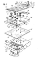
- the fluid control device 10 includes a generally rectangular housing 12, a fluid inlet port 14, a fluid outlet port 16 and an electric power connection 18.
- a generally rectangular valve body 20 having a chamber or passageway 22 communicating with the input port 14 and the outlet port 16, a membrane 24, a mounting block 26, a piezoelectric driver mechanism 28, an impacting member 30, and clamping member 32.
- the fluid is contained entirely within the chamber 22 defined by the valve body 20 and the membrane 24, whereby the impacting member 30 and the piezoelectric driver mechanism 28 are separated from the fluid.
- the chamber 22 within the valve body 20 is arranged to provide a valve seat 29.
- the valve seat 29 is substantially coplanar with the generally planar surface 21 of the valve body 20.
- the membrane 24 is a strong, pliable member and can be formed of a polymer material, such as the material sold under the registered trademark of TEFLON by Dupont Company, or any of various elastomers or rubber.
- the material for the membrane 24 must be selected on the basis of abrasion resistance and chemical compatibility with the fluid as well as its elasticity and resilience characteristics.
- the membrane 24 can be provided corresponding in dimensions to the rectangular valve body 20, except with a generally thin wall thickness, for example 0.015 inches (0.38 mm).
- the membrane 24 is secured to the upper, generally planar surface 21 of the valve body 20 and is arranged movably and resiliently in a vertical plane with the valve seat 29.
- the membrane 24 functions as a gasket by sealing around the openings for mounting screws.
- the membrane 24 provides a fluid-tight seal at the valve seat 29 with the impacting member 30 exerting a predetermined force on the membrane 24.
- Mounting screws 36 are employed to couple the mounting block 26, membrane 24 and the valve body 20 and additionally to provide the clamping around the chamber. Openings 34 are provided in the membrane 24 to allow passage of a mounting screw 36. Corresponding openings 38 are provided in the valve body 20 to receive the mounting screws 36. The use of the mounting screws 36 conveniently enables exchanging of the membrane 24 should it be necessary, depending on the chemical nature of the fluid to be controlled.
- the mounting block 26 is provided with openings 40 to receive the mounting screws 36. Second openings 42 are provided to receive mounting screws 44. The mounting screws 44 are employed to couple the clamping member 32, the piezoelectric driver mechanism 28, the spacer 52 and the mounting block 26. A third opening 46 is provided in the mounting block 26 to retain the impacting member 30 in position concentric with the valve seat 29 in the valve body 20 and in a vertical plane therewith.
- the mounting block 26 can be substantially equal in overall dimensions to the rectangular valve body 20.
- the piezoelectric driver mechanism 28 is provided as a rectangular bar having overall dimensions less than the overall dimensions of the valve body 20.
- the piezoelectric driver mechanism 28 is illustrated in Figures 2 and 3 as two like piezoelectric members, wafers 48A, 48B, secured together.
- the number of the piezoelectric members 48A, 48B secured together in a stack determines the total force that can be generated by the driver mechanism 28.
- the total force that can be generated by the driver mechanism 28 increases in proportion to the number of piezoelectric members 48A, 48B provided in the stack.
- the number of piezoelectric members 48A, 48B is selected to satisfy the operating requirement of the particular application.
- the piezoelectric members 48A, 48B are secured together and are connected electrically in parallel.
- the stack of two like piezoelectric members 48A, 48B can provide a driver mechanism having a thickness of about 1/32 inch (0.79 mm). Although illustrated as connected electrically in parallel, a series connection of the piezoelectric members 48A and 48B is feasible within the skill in the art.
- the electrical power connection 18 is provided to the upper and lower surfaces of the piezoelectric driver mechanism 28 and is connected to a variable D.C. power supply 50.
- the piezoelectric driver mechanism 28 is cantilever mounted at its fixed end through a spacer 52 to the mounting block 26.
- the free-end of the piezoelectric driver mechanism 28 is arranged to move toward and away from the impacting member 30 in predetermined relation to the polarity and level of the applied voltage.
- the amplitude of the movement or deflection of the free-end of the piezoelectric driver mechanism 28 increases corresponding to increases in the level of the applied voltage, so that valve 10 can be used as a throttle valve by varying the level of the applied voltage.
- FIG. 2 illustrates a normally closed valve 10; the piezoelectric driver mechanism 28 is mechanically deflected and holding the impacting member 30 against the membrane 24, and membrane 24 against the valve seat 29 with the power source 50 deactivated.
- the driver mechanism 28 is arranged to provide a fluid-tight sealed engagement between the membrane 24 and the valve seat 29 with the electrical power source 50 deactivated.
- the free end of the piezoelectric driver mechanism 28 is caused to further deflect and move away from the impacting member 30 by activating the electrical power source 50, thereby providing a path for fluid flow through chamber 22.
- the amount of fluid flow can be controlled by varying the level of the voltage applied to the piezoelectric driver mechanism 28 and also, the time duration of the applied voltage.
- Figure 3 illustrates a normally open valve 10 wherein the piezoelectric driver mechanism 28 is arranged to provide a path for fluid flow through chamber 22 when the power source 50 is deactivated.
- the spacer 52 is provided with additional height than is used for the normally closed valve illustrated in Figure 2.
- the free-end of the piezoelectric driver mechanism 28 is disposed at a higher position whereby the fluid flows from inlet port 14 through the chamber 22 and past valve seat 29 to the outlet port 16 with the power source 50 deactivated.
- the free-end of the piezoelectric driver mechanism 28 is caused to deflect and move toward the impacting member 30 by activating the electrical power source 50, thereby throttling the fluid flow through chamber 22.
- the free end of the piezoelectric driver mechanism 28 moves the impacting member 30 against the membrane 24, such that the membrane 24 exerts a fluid-tight sealing force on the valve seat 29 and closes chamber 22.
- the vertical dimension of the spacer 52 can be used to provide for a normally closed or normally open valve with the polarity of the electrical connection 18 determining the direction of movement of the deflectable portion of the piezoelectric driver mechanism 28.
- one inlet port 14' and seven outlet ports 16A, 16B, 16C, 16D, 16E, 16F, 16G are provided.
- a separate and individual electrical connection 18' is provided to each of the seven fluid control devices thereby providing for separate and independent operation of each.
- FIG. 5 is an exploded perspective view of a multiple valve body including four fluid control devices.
- the valve body 20' has a chamber 22' connecting the input port 14' to the four outlet ports 16A, 16B, 16C, 16D and is arranged to provide four valve seats 29A, 29B, 29C, 29D. Openings 38' are provided in the valve body 20' to receive mounting screws 36'.
- a membrane 24' is secured to the upper, generally planar surface of the valve body 20' and is arranged movable and resiliently in the vertical planes with the valve seats 29A, 29B, 29C, 29D.
- openings 34' are provided in the membrane 24' to allow passage of the mounting screws.
- a mounting block 26' is provided with openings 40' corresponding to openings 34' in the membrane 24' to receive the mounting screws 36' that couple the mounting block 26', the membrane 24' and valve body 20'.
- a pair of openings 42' are provided in the mounting block to receive mounting screws 44' that couple the mounting block 26' to clamping member 32' with the piezoelectric driver mechanism 28' and the spacer 52' secured therebetween.
- Openings 46A, 46B, 46C, 46D are provided in the mounting block 26' to retain impacting members 30A, 30B, 30C, 30D and are disposed in the vertical planes with the valve seats 29A, 29B, 29C and 29D.
- the mounting block 26' can be substantially equal in overall dimensions to the valve body 20'.
- the piezoelectric driver mechanism 28' includes four electrically separate drivers 28A, 28B, 28C, 28D with a separate electrical power connection 18A, 18B, 18C, 18D provided to each for individual control.
- the piezoelectric drivers 28A, 28B, 28C, 28D are illustrated as a stack of four like piezoelectric members 48A, 48B, 48C, 38D.
- a spacer 52' is employed to determine the separation between the free-ends of the piezoelectric driver mechanism 28A, .28B, 28C, 28D and the impacting members 30A, 30B, 30C, 30D to provide either all normally open or all normally closed valves as hereinbefore described for a single valve 10 as illustrated in Figures 1, 2 and 3.
- the multiple fluid control devices illustrated in Figures 4 and 5 provide for independent, high speed operation and accuracy without residual motion for each of the separate, closely-spaced valves.
- a multiple valve body (not shown) can be provided with a plurality of inlet ports corresponding to a plurality of outlet ports.
- the provision of multiple inlet ports could be useful in fluid control logic applications.
- Fluid control devices embodying the invention can be employed in a variety of different applications. Among such applications could be selected dispensing of inks, dyes or the like in the computer printing field, controlled dispensing of medicinals from pumps, implanted in a human for instance, controlling fluid flow in fluidic systems among others.
- member 30 has been illustrated as a sphere or ball to provide a surface which can cooperate with the valve seat 29 and membrane 24, it will be understood that member 30 may have a different configuration within the purview of the invention.
- member 30 may be a cylinder or a flattened ball which presents such a cooperating surface with the valve seat, including the member 24.
- the impact member 30 may have other useful configurations.
- the term "polyhedral-like member", as used herein, shall be construed to include any configuration of impact member suitable for the purposes described.
Landscapes
- Engineering & Computer Science (AREA)
- General Engineering & Computer Science (AREA)
- Mechanical Engineering (AREA)
- Physics & Mathematics (AREA)
- General Physics & Mathematics (AREA)
- Automation & Control Theory (AREA)
- Electrically Driven Valve-Operating Means (AREA)
- Flow Control (AREA)
- Valve Housings (AREA)
- Fluid-Pressure Circuits (AREA)
Claims (6)
Priority Applications (1)
| Application Number | Priority Date | Filing Date | Title |
|---|---|---|---|
| AT83306728T ATE26749T1 (de) | 1982-11-12 | 1983-11-04 | Piezo-elektrisches fluidsteuergeraet. |
Applications Claiming Priority (2)
| Application Number | Priority Date | Filing Date | Title |
|---|---|---|---|
| US440966 | 1982-11-12 | ||
| US06/440,966 US4450375A (en) | 1982-11-12 | 1982-11-12 | Piezoelectric fluid control device |
Publications (2)
| Publication Number | Publication Date |
|---|---|
| EP0109239A1 EP0109239A1 (de) | 1984-05-23 |
| EP0109239B1 true EP0109239B1 (de) | 1987-04-22 |
Family
ID=23750950
Family Applications (1)
| Application Number | Title | Priority Date | Filing Date |
|---|---|---|---|
| EP19830306728 Expired EP0109239B1 (de) | 1982-11-12 | 1983-11-04 | Piezo-elektrisches Fluidsteuergerät |
Country Status (14)
| Country | Link |
|---|---|
| US (1) | US4450375A (de) |
| EP (1) | EP0109239B1 (de) |
| JP (1) | JPS59140980A (de) |
| KR (1) | KR890000076B1 (de) |
| AT (1) | ATE26749T1 (de) |
| AU (1) | AU559913B2 (de) |
| CA (1) | CA1218640A (de) |
| DE (1) | DE3371113D1 (de) |
| DK (1) | DK516383A (de) |
| GB (1) | GB2131130B (de) |
| HK (1) | HK84686A (de) |
| IE (1) | IE54778B1 (de) |
| IL (1) | IL70200A (de) |
| ZA (1) | ZA838426B (de) |
Cited By (1)
| Publication number | Priority date | Publication date | Assignee | Title |
|---|---|---|---|---|
| CN104781077A (zh) * | 2012-09-12 | 2015-07-15 | 船井电机株式会社 | 微流体喷射头的维护阀 |
Families Citing this family (94)
| Publication number | Priority date | Publication date | Assignee | Title |
|---|---|---|---|---|
| AT380934B (de) * | 1983-01-13 | 1986-07-25 | Enfo Grundlagen Forschungs Ag | Elektrisch-pneumatischer signalwandler |
| JPS6046636U (ja) * | 1983-09-05 | 1985-04-02 | オムロン株式会社 | 多極リレ− |
| JPS6116867A (ja) * | 1984-05-29 | 1986-01-24 | Yasuhiko Ogawa | 櫛型の圧電駆動装置 |
| US4575697A (en) * | 1984-06-18 | 1986-03-11 | Sperry Corporation | Electrically controlled phase shifter |
| DE3428969A1 (de) * | 1984-08-06 | 1986-02-13 | Siemens AG, 1000 Berlin und 8000 München | Steuervorrichtung zur luftklappenbetaetigung |
| US4620123A (en) * | 1984-12-21 | 1986-10-28 | General Electric Company | Synchronously operable electrical current switching apparatus having multiple circuit switching capability and/or reduced contact resistance |
| AT382431B (de) * | 1985-02-08 | 1987-02-25 | Enfo Grundlagen Forschungs Ag | Elektrisch-pneumatischer signalwandler |
| US4629926A (en) * | 1985-10-21 | 1986-12-16 | Kiwi Coders Corporation | Mounting for piezoelectric bender of fluid control device |
| EP0243249A1 (de) * | 1986-04-18 | 1987-10-28 | Maurice Carre | Vorrichtung zur Abgabe eines Produktes in vorbestimmten dosierten Mengen, insbesondere für medizinische Zwecke |
| US4697118A (en) * | 1986-08-15 | 1987-09-29 | General Electric Company | Piezoelectric switch |
| US4723131A (en) * | 1986-09-12 | 1988-02-02 | Diagraph Corporation | Printhead for ink jet printing apparatus |
| GB8700203D0 (en) * | 1987-01-07 | 1987-02-11 | Domino Printing Sciences Plc | Ink jet printing head |
| US4771204A (en) * | 1987-07-30 | 1988-09-13 | Kiwi Coders Corporation | Sealing method and means for fluid control device |
| US4841256A (en) * | 1987-10-20 | 1989-06-20 | Pennwalt Corporation | Piezoelectric phase locked loop circuit |
| US4808874A (en) * | 1988-01-06 | 1989-02-28 | Ford Aerospace Corporation | Double saggital stroke amplifier |
| US4933591A (en) * | 1988-01-06 | 1990-06-12 | Ford Aerospace Corporation | Double saggital pull stroke amplifier |
| DE3814150A1 (de) * | 1988-04-27 | 1989-11-09 | Draegerwerk Ag | Ventilanordnung aus mikrostrukturierten komponenten |
| JPH02274550A (ja) * | 1989-04-17 | 1990-11-08 | Komori Corp | 画像記録装置のヘッド制御方法 |
| US5094594A (en) * | 1990-04-23 | 1992-03-10 | Genomyx, Incorporated | Piezoelectric pumping device |
| US5126755A (en) * | 1991-03-26 | 1992-06-30 | Videojet Systems International, Inc. | Print head assembly for ink jet printer |
| JPH05124186A (ja) * | 1991-11-06 | 1993-05-21 | Brother Ind Ltd | 液滴噴射装置 |
| US6394412B2 (en) | 1993-04-02 | 2002-05-28 | Netafim (A.C.S.) Ltd. | Controlled valve |
| EP1129739B1 (de) * | 1993-10-04 | 2008-08-13 | Research International, Inc. | Mikrobearbeitete Filter |
| DE19735156C1 (de) * | 1996-11-25 | 1999-04-29 | Fraunhofer Ges Forschung | Piezoelektrisch betätigtes Mikroventil |
| DE19648730C2 (de) * | 1996-11-25 | 1998-11-19 | Fraunhofer Ges Forschung | Piezoelektrisch betätigtes Mikroventil |
| DE69827019T2 (de) | 1997-05-20 | 2006-02-02 | Zymequest, Inc., Beverly | Gerät und verfahren zur verarbeitung von biologischen zellen |
| DE19723388C1 (de) * | 1997-06-04 | 1998-07-02 | Draegerwerk Ag | Modulare Piezoventilanordnung |
| JP3842870B2 (ja) * | 1997-07-11 | 2006-11-08 | Smc株式会社 | 開閉弁 |
| US6082185A (en) * | 1997-07-25 | 2000-07-04 | Research International, Inc. | Disposable fluidic circuit cards |
| US6200532B1 (en) | 1998-11-20 | 2001-03-13 | Akzo Nobel Nv | Devices and method for performing blood coagulation assays by piezoelectric sensing |
| SE9904264D0 (sv) * | 1999-11-25 | 1999-11-25 | Markpoint Ab | Ventilanordning |
| DK1207329T3 (da) * | 2000-11-20 | 2003-04-22 | Festo Ag & Co | Piezoventil |
| DE20019705U1 (de) * | 2000-11-20 | 2001-02-15 | Festo AG & Co, 73734 Esslingen | Piezo-Biegewandlereinheit und damit ausgestattetes Piezoventil |
| MXPA04000103A (es) * | 2001-07-03 | 2005-01-07 | Davis Boyd Clark | Sistema de iniciacion con conmutacion auto-impulsado. |
| US20040003786A1 (en) * | 2002-06-18 | 2004-01-08 | Gatecliff George W. | Piezoelectric valve actuation |
| US7338433B2 (en) | 2002-08-13 | 2008-03-04 | Allergan, Inc. | Remotely adjustable gastric banding method |
| ES2617452T3 (es) | 2002-08-28 | 2017-06-19 | Apollo Endosurgery, Inc | Dispositivo de banda gástrica resistente a la fatiga |
| IL152865A0 (en) * | 2002-11-14 | 2003-06-24 | Q Core Ltd | Peristalic pump |
| US7475607B2 (en) * | 2004-01-08 | 2009-01-13 | Honeywell International Inc. | Sensing apparatus with an integrated gasket on a beam component |
| PT2399528E (pt) * | 2004-01-23 | 2013-02-26 | Allergan Inc | Banda gástrica regulável de uma só peça, que pode ser fixada de forma amovível |
| DK1564464T3 (da) * | 2004-02-11 | 2006-05-29 | Festo Ag & Co | Piezoventil |
| DE102004010583B4 (de) * | 2004-03-02 | 2006-01-12 | Ab Skf | Ölabscheider |
| WO2005084952A1 (de) * | 2004-03-03 | 2005-09-15 | Rea Elektronik Gmbh | Tintenstrahl-schreibkopf |
| AU2005221413B2 (en) | 2004-03-08 | 2010-09-23 | Endoart S.A. | Closure system for tubular organs |
| DE102004017178A1 (de) * | 2004-04-07 | 2005-11-03 | Siemens Ag | Vorrichtung und Verfahren zum Betätigen eines Ventils in einem mikromechanischen Gerät |
| WO2005110759A1 (de) * | 2004-05-11 | 2005-11-24 | Rea Elektronik Gmbh | Tintenstrahl-schreibkopf |
| IL165365A0 (en) * | 2004-11-24 | 2006-01-15 | Q Core Ltd | Finger-type peristaltic pump |
| US8308457B2 (en) * | 2004-11-24 | 2012-11-13 | Q-Core Medical Ltd. | Peristaltic infusion pump with locking mechanism |
| US8251888B2 (en) * | 2005-04-13 | 2012-08-28 | Mitchell Steven Roslin | Artificial gastric valve |
| US8043206B2 (en) | 2006-01-04 | 2011-10-25 | Allergan, Inc. | Self-regulating gastric band with pressure data processing |
| US8535025B2 (en) | 2006-11-13 | 2013-09-17 | Q-Core Medical Ltd. | Magnetically balanced finger-type peristaltic pump |
| IL179231A0 (en) * | 2006-11-13 | 2007-03-08 | Q Core Ltd | A finger-type peristaltic pump comprising a ribbed anvil |
| IL179234A0 (en) * | 2006-11-13 | 2007-03-08 | Q Core Ltd | An anti-free flow mechanism |
| EP2362762A1 (de) | 2008-10-06 | 2011-09-07 | Allergan Medical Sàrl | Mechanisches magenband mit polstern |
| US20100305397A1 (en) * | 2008-10-06 | 2010-12-02 | Allergan Medical Sarl | Hydraulic-mechanical gastric band |
| US20100185049A1 (en) | 2008-10-22 | 2010-07-22 | Allergan, Inc. | Dome and screw valves for remotely adjustable gastric banding systems |
| WO2010048280A1 (en) * | 2008-10-22 | 2010-04-29 | Allergan, Inc. | Electrically activated valve for implantable fluid handling system |
| US8371832B2 (en) | 2009-12-22 | 2013-02-12 | Q-Core Medical Ltd. | Peristaltic pump with linear flow control |
| US8142400B2 (en) * | 2009-12-22 | 2012-03-27 | Q-Core Medical Ltd. | Peristaltic pump with bi-directional pressure sensor |
| US8678993B2 (en) * | 2010-02-12 | 2014-03-25 | Apollo Endosurgery, Inc. | Remotely adjustable gastric banding system |
| US20110201874A1 (en) * | 2010-02-12 | 2011-08-18 | Allergan, Inc. | Remotely adjustable gastric banding system |
| US8758221B2 (en) | 2010-02-24 | 2014-06-24 | Apollo Endosurgery, Inc. | Source reservoir with potential energy for remotely adjustable gastric banding system |
| US8840541B2 (en) * | 2010-02-25 | 2014-09-23 | Apollo Endosurgery, Inc. | Pressure sensing gastric banding system |
| US8764624B2 (en) * | 2010-02-25 | 2014-07-01 | Apollo Endosurgery, Inc. | Inductively powered remotely adjustable gastric banding system |
| WO2011128850A2 (en) | 2010-04-12 | 2011-10-20 | Q Core Medical Ltd | Air trap for intravenous pump |
| US20110270024A1 (en) | 2010-04-29 | 2011-11-03 | Allergan, Inc. | Self-adjusting gastric band having various compliant components |
| US9044298B2 (en) | 2010-04-29 | 2015-06-02 | Apollo Endosurgery, Inc. | Self-adjusting gastric band |
| US9028394B2 (en) | 2010-04-29 | 2015-05-12 | Apollo Endosurgery, Inc. | Self-adjusting mechanical gastric band |
| US9226840B2 (en) | 2010-06-03 | 2016-01-05 | Apollo Endosurgery, Inc. | Magnetically coupled implantable pump system and method |
| US8517915B2 (en) | 2010-06-10 | 2013-08-27 | Allergan, Inc. | Remotely adjustable gastric banding system |
| US8698373B2 (en) | 2010-08-18 | 2014-04-15 | Apollo Endosurgery, Inc. | Pare piezo power with energy recovery |
| US9211207B2 (en) | 2010-08-18 | 2015-12-15 | Apollo Endosurgery, Inc. | Power regulated implant |
| US20120059216A1 (en) | 2010-09-07 | 2012-03-08 | Allergan, Inc. | Remotely adjustable gastric banding system |
| WO2012094016A1 (en) * | 2011-01-07 | 2012-07-12 | Hewlett-Packard Development Company, L.P. | Integrated multifunctional valve device |
| KR101855968B1 (ko) | 2011-01-07 | 2018-05-09 | 휴렛-팩커드 디벨롭먼트 컴퍼니, 엘.피. | 복수의 챔버 및 밸브를 갖는 유체 용기 |
| KR20180016647A (ko) | 2011-01-07 | 2018-02-14 | 휴렛-팩커드 디벨롭먼트 컴퍼니, 엘.피. | 복수의 챔버를 갖는 유체 용기 |
| WO2012095829A2 (en) | 2011-01-16 | 2012-07-19 | Q-Core Medical Ltd. | Methods, apparatus and systems for medical device communication, control and localization |
| WO2013001425A2 (en) | 2011-06-27 | 2013-01-03 | Q-Core Medical Ltd. | Methods, circuits, devices, apparatuses, encasements and systems for identifying if a medical infusion system is decalibrated |
| US8876694B2 (en) | 2011-12-07 | 2014-11-04 | Apollo Endosurgery, Inc. | Tube connector with a guiding tip |
| US8961394B2 (en) | 2011-12-20 | 2015-02-24 | Apollo Endosurgery, Inc. | Self-sealing fluid joint for use with a gastric band |
| US9855110B2 (en) | 2013-02-05 | 2018-01-02 | Q-Core Medical Ltd. | Methods, apparatus and systems for operating a medical device including an accelerometer |
| GB2516847A (en) * | 2013-07-31 | 2015-02-11 | Ingegneria Ceramica S R L | An Improved Actuator For A Printhead |
| CN105782459A (zh) * | 2014-12-19 | 2016-07-20 | 昆达电脑科技(昆山)有限公司 | 依湿度自动开关的阀 |
| TWI599868B (zh) * | 2016-09-05 | 2017-09-21 | 研能科技股份有限公司 | 流體控制裝置之製造方法 |
| US11639057B2 (en) | 2018-05-11 | 2023-05-02 | Matthews International Corporation | Methods of fabricating micro-valves and jetting assemblies including such micro-valves |
| KR20210018835A (ko) | 2018-05-11 | 2021-02-18 | 매튜 인터내셔널 코포레이션 | 제팅 조립체에 사용되는 마이크로-밸브용 전극 구조체 |
| US10994535B2 (en) | 2018-05-11 | 2021-05-04 | Matthews International Corporation | Systems and methods for controlling operation of micro-valves for use in jetting assemblies |
| WO2019215668A1 (en) | 2018-05-11 | 2019-11-14 | Matthews International Corporation | Micro-valves for use in jetting assemblies |
| AU2019265877B2 (en) | 2018-05-11 | 2024-10-03 | Matthews International Corporation | Systems and methods for sealing micro-valves for use in jetting assemblies |
| GB2583059B (en) * | 2019-01-30 | 2024-01-31 | Cn Bio Innovations Ltd | A microvalve, and a multi-directional valve apparatus |
| CN114930058A (zh) | 2019-11-01 | 2022-08-19 | 马修斯国际公司 | 包括喷注总成的非接触式沉积系统 |
| ES2933693T3 (es) | 2019-11-18 | 2023-02-13 | Eitan Medical Ltd | Prueba rápida para bomba médica |
| DE102020002351B4 (de) * | 2020-04-19 | 2024-09-19 | Exel Industries Sa | Druckkopf mit mikropneumatischer Steuereinheit |
| IT202300002931A1 (it) * | 2023-02-21 | 2024-08-21 | Camozzi Automation S P A | Valvola piezoelettrica |
Family Cites Families (19)
| Publication number | Priority date | Publication date | Assignee | Title |
|---|---|---|---|---|
| GB853469A (en) * | 1955-12-21 | 1960-11-09 | Baird & Tatlock Ltd | Improvements in or relating to valves for controlling fluid flow |
| GB901226A (en) * | 1959-01-16 | 1962-07-18 | Council Scient Ind Res | Improvements in fluid flow controllers |
| GB963051A (en) * | 1961-10-16 | 1964-07-08 | Jose Marlet Barrera | Improved valve for liquids |
| US3456669A (en) * | 1966-10-20 | 1969-07-22 | Fisher Governor Co | Piezoelectric transducer |
| GB1270879A (en) * | 1969-10-30 | 1972-04-19 | Santon Ltd | Electrically controlled valve |
| US3614486A (en) * | 1969-11-10 | 1971-10-19 | Physics Int Co | Lever motion multiplier driven by electroexpansive material |
| DE2042066B2 (de) * | 1970-08-25 | 1971-10-14 | Mersch Fonderies Atel | Membranventil |
| DE2226365A1 (de) * | 1971-06-02 | 1972-12-14 | British Oxygen Co Ltd | Einlaßventil, insbesondere für Unterdruckbehälter |
| DE2426748C3 (de) * | 1974-06-01 | 1979-10-11 | Buerkert Gmbh, 7118 Ingelfingen | Mehrwegemagnetventil für aggressive Medien |
| US4011474A (en) * | 1974-10-03 | 1977-03-08 | Pz Technology, Inc. | Piezoelectric stack insulation |
| DE2527647C3 (de) * | 1975-06-20 | 1981-06-25 | Siemens AG, 1000 Berlin und 8000 München | Mit Flüssigkeitströpfchen arbeitendes Schreibgerät |
| US4032929A (en) * | 1975-10-28 | 1977-06-28 | Xerox Corporation | High density linear array ink jet assembly |
| US4099700A (en) * | 1977-02-16 | 1978-07-11 | Wen Young | Flow control device for fluids flowing in a closed conduit |
| DE2752549A1 (de) * | 1977-11-24 | 1979-06-07 | Boehringer Mannheim Gmbh | Ventil zur steuerung von stroemungsmedien |
| GB1593495A (en) * | 1978-02-24 | 1981-07-15 | Ti Domestic Appliances Ltd | Thermally actuated gas flow control valve assemblies |
| US4340083A (en) * | 1978-11-30 | 1982-07-20 | Carleton Controls Corporation | Deflectable beam valve |
| DE2918377A1 (de) * | 1979-05-07 | 1980-11-20 | Schenck Ag Carl | Ventil fuer stroemende medien |
| US4318023A (en) * | 1980-02-21 | 1982-03-02 | Physics International Company | Sagittally amplified piezoelectric actuator |
| JPS57136859U (de) * | 1981-02-18 | 1982-08-26 |
-
1982
- 1982-11-12 US US06/440,966 patent/US4450375A/en not_active Expired - Fee Related
-
1983
- 1983-11-04 AT AT83306728T patent/ATE26749T1/de not_active IP Right Cessation
- 1983-11-04 GB GB8329539A patent/GB2131130B/en not_active Expired
- 1983-11-04 DE DE8383306728T patent/DE3371113D1/de not_active Expired
- 1983-11-04 EP EP19830306728 patent/EP0109239B1/de not_active Expired
- 1983-11-10 CA CA000440942A patent/CA1218640A/en not_active Expired
- 1983-11-11 ZA ZA838426A patent/ZA838426B/xx unknown
- 1983-11-11 IL IL7020083A patent/IL70200A/xx unknown
- 1983-11-11 JP JP58211120A patent/JPS59140980A/ja active Pending
- 1983-11-11 IE IE2642/83A patent/IE54778B1/en unknown
- 1983-11-11 KR KR1019830005358A patent/KR890000076B1/ko not_active Expired
- 1983-11-11 DK DK516383A patent/DK516383A/da not_active Application Discontinuation
- 1983-11-11 AU AU21177/83A patent/AU559913B2/en not_active Ceased
-
1986
- 1986-11-06 HK HK846/86A patent/HK84686A/xx unknown
Cited By (1)
| Publication number | Priority date | Publication date | Assignee | Title |
|---|---|---|---|---|
| CN104781077A (zh) * | 2012-09-12 | 2015-07-15 | 船井电机株式会社 | 微流体喷射头的维护阀 |
Also Published As
| Publication number | Publication date |
|---|---|
| JPS59140980A (ja) | 1984-08-13 |
| DK516383D0 (da) | 1983-11-11 |
| KR840006517A (ko) | 1984-11-30 |
| GB2131130A (en) | 1984-06-13 |
| KR890000076B1 (ko) | 1989-03-07 |
| AU2117783A (en) | 1984-05-17 |
| IL70200A (en) | 1987-11-30 |
| GB2131130B (en) | 1986-03-19 |
| IL70200A0 (en) | 1984-02-29 |
| GB8329539D0 (en) | 1983-12-07 |
| ATE26749T1 (de) | 1987-05-15 |
| IE54778B1 (en) | 1990-01-31 |
| DK516383A (da) | 1984-05-13 |
| DE3371113D1 (en) | 1987-05-27 |
| EP0109239A1 (de) | 1984-05-23 |
| HK84686A (en) | 1986-11-14 |
| ZA838426B (en) | 1985-07-31 |
| IE832642L (en) | 1984-05-12 |
| AU559913B2 (en) | 1987-03-26 |
| US4450375A (en) | 1984-05-22 |
| CA1218640A (en) | 1987-03-03 |
Similar Documents
| Publication | Publication Date | Title |
|---|---|---|
| EP0109239B1 (de) | Piezo-elektrisches Fluidsteuergerät | |
| US4629926A (en) | Mounting for piezoelectric bender of fluid control device | |
| US5765591A (en) | Valve apparatus and method for distributing fluids | |
| US6458325B1 (en) | Apparatus for analyzing liquid samples automatically and continually | |
| CA1254185A (en) | Actuator for control valves and related systems | |
| US4771204A (en) | Sealing method and means for fluid control device | |
| JP3900112B2 (ja) | 圧電弁 | |
| US6142444A (en) | Piezoelectrically actuated microvalve | |
| KR100256167B1 (ko) | 흡출밸브 | |
| US5433244A (en) | Solenoid control valve | |
| EP0314286B1 (de) | Eine Silikon-Ventileinrichtung zur Kontrolle des Durchflusses | |
| KR100194194B1 (ko) | 회전다이아프램형 유량제어밸브 | |
| US4828218A (en) | Multiple mode regulator | |
| US6830071B2 (en) | Microvalve devices | |
| EP0081910B1 (de) | Motorisch angetriebenes Durchflussregelventil | |
| US5081328A (en) | Flow switch | |
| CA1250446A (en) | Differential pressure transmitter | |
| EP0319618B1 (de) | Elektromagnetisches Ventil | |
| US4782860A (en) | Magnetic flow control valve | |
| JP2001194375A (ja) | 液体を開放噴流にて付与する微量分配システム | |
| EP1778978A1 (de) | Modifizierter doppelmembran-drucksensor | |
| US4273976A (en) | Pressure responsive switch device | |
| CN114060257A (zh) | 流体设备 | |
| JP3619490B2 (ja) | 電空変換式空気レギュレータ | |
| US3774639A (en) | Valve |
Legal Events
| Date | Code | Title | Description |
|---|---|---|---|
| PUAI | Public reference made under article 153(3) epc to a published international application that has entered the european phase |
Free format text: ORIGINAL CODE: 0009012 |
|
| AK | Designated contracting states |
Designated state(s): AT BE CH DE FR IT LI LU NL SE |
|
| 17P | Request for examination filed |
Effective date: 19841030 |
|
| GRAA | (expected) grant |
Free format text: ORIGINAL CODE: 0009210 |
|
| AK | Designated contracting states |
Kind code of ref document: B1 Designated state(s): AT BE CH DE FR IT LI LU NL SE |
|
| PG25 | Lapsed in a contracting state [announced via postgrant information from national office to epo] |
Ref country code: LI Effective date: 19870422 Ref country code: CH Effective date: 19870422 Ref country code: BE Effective date: 19870422 Ref country code: AT Effective date: 19870422 |
|
| REF | Corresponds to: |
Ref document number: 26749 Country of ref document: AT Date of ref document: 19870515 Kind code of ref document: T |
|
| ITF | It: translation for a ep patent filed | ||
| REF | Corresponds to: |
Ref document number: 3371113 Country of ref document: DE Date of ref document: 19870527 |
|
| ET | Fr: translation filed | ||
| REG | Reference to a national code |
Ref country code: CH Ref legal event code: PL |
|
| PG25 | Lapsed in a contracting state [announced via postgrant information from national office to epo] |
Ref country code: LU Free format text: LAPSE BECAUSE OF NON-PAYMENT OF DUE FEES Effective date: 19871130 |
|
| PLBE | No opposition filed within time limit |
Free format text: ORIGINAL CODE: 0009261 |
|
| STAA | Information on the status of an ep patent application or granted ep patent |
Free format text: STATUS: NO OPPOSITION FILED WITHIN TIME LIMIT |
|
| 26N | No opposition filed | ||
| PGFP | Annual fee paid to national office [announced via postgrant information from national office to epo] |
Ref country code: FR Payment date: 19891107 Year of fee payment: 7 |
|
| PGFP | Annual fee paid to national office [announced via postgrant information from national office to epo] |
Ref country code: NL Payment date: 19891130 Year of fee payment: 7 |
|
| PGFP | Annual fee paid to national office [announced via postgrant information from national office to epo] |
Ref country code: SE Payment date: 19901114 Year of fee payment: 8 |
|
| ITTA | It: last paid annual fee | ||
| PGFP | Annual fee paid to national office [announced via postgrant information from national office to epo] |
Ref country code: DE Payment date: 19901228 Year of fee payment: 8 |
|
| PG25 | Lapsed in a contracting state [announced via postgrant information from national office to epo] |
Ref country code: NL Effective date: 19910601 |
|
| NLV4 | Nl: lapsed or anulled due to non-payment of the annual fee | ||
| PG25 | Lapsed in a contracting state [announced via postgrant information from national office to epo] |
Ref country code: FR Effective date: 19910731 |
|
| REG | Reference to a national code |
Ref country code: FR Ref legal event code: ST |
|
| PG25 | Lapsed in a contracting state [announced via postgrant information from national office to epo] |
Ref country code: SE Effective date: 19911105 |
|
| PG25 | Lapsed in a contracting state [announced via postgrant information from national office to epo] |
Ref country code: DE Effective date: 19920801 |
|
| EUG | Se: european patent has lapsed |
Ref document number: 83306728.3 Effective date: 19920604 |