EP0109080A1 - Aufnahmekopf zum Bewegen von blattförmigem Material - Google Patents
Aufnahmekopf zum Bewegen von blattförmigem Material Download PDFInfo
- Publication number
- EP0109080A1 EP0109080A1 EP83111346A EP83111346A EP0109080A1 EP 0109080 A1 EP0109080 A1 EP 0109080A1 EP 83111346 A EP83111346 A EP 83111346A EP 83111346 A EP83111346 A EP 83111346A EP 0109080 A1 EP0109080 A1 EP 0109080A1
- Authority
- EP
- European Patent Office
- Prior art keywords
- pick
- head
- slots
- flow
- sheet
- Prior art date
- Legal status (The legal status is an assumption and is not a legal conclusion. Google has not performed a legal analysis and makes no representation as to the accuracy of the status listed.)
- Granted
Links
Images


Classifications
-
- H—ELECTRICITY
- H10—SEMICONDUCTOR DEVICES; ELECTRIC SOLID-STATE DEVICES NOT OTHERWISE PROVIDED FOR
- H10P—GENERIC PROCESSES OR APPARATUS FOR THE MANUFACTURE OR TREATMENT OF DEVICES COVERED BY CLASS H10
- H10P72/00—Handling or holding of wafers, substrates or devices during manufacture or treatment thereof
- H10P72/70—Handling or holding of wafers, substrates or devices during manufacture or treatment thereof for supporting or gripping
- H10P72/78—Handling or holding of wafers, substrates or devices during manufacture or treatment thereof for supporting or gripping using vacuum or suction, e.g. Bernoulli chucks
Definitions
- This invention relates to a pick-up and transfer head for handling flexible and fragile materials, in particular by employing aspirated air flow to transfer flexible and fragile materials while maintaining them in a planar shape.
- ceramic modules having multiple layers require transportation during various processing steps. These modules comprise multiple layers of ceramic materials with each sheet or layers of the ceramic having a particular conductive pattern imprinted thereon. Typically, the layers are aligned to provide a stack of uncured ceramics which is then pressed and cured to form an integral ceramic package having a very large number of electrically connected conductive paths arranged therein.
- each of the layers and the stack itself is flexible and highly fragile.
- U.S. Patents 3 539 216 and 3 411 770 Other devices to lift objects having a flat surface by means of this flow phenomenon are shown and described in U.S. Patents 3 539 216 and 3 411 770.
- flow conditions are established in radially opposite directions across the surface of the body for lifting by Bernoulli effect. The flow may be directed in an unbalanced state over the surface to urge the wafer against a lateral restraint.
- a jet of air is directed vertically downward onto a stack of sheets. The velocity of the vertical stream in its radial excursion then creates a pressure differential acting to lift the top sheet of the stack when it is displaced at a predetermined position.
- a technique distinguishable from Bernoulli effects in the prior art employs the application of a vacuum by which objects are lifted utilizing an array of suction ports on the transportation head which are in turn connected to a remote source of vacuum.
- the vacuum source may be either a vacuum pump or the throat section of a venturi tube.
- Typical are the techniques disclosed in U.S. Patent 3 648 853 and U.S. Patent 4 185 814.
- a plurality of pick-up vacuum cups are connected to the throat of a venturi tube to effectuate lifting of a flat work piece.
- a pick-up head is positioned in a fixed vertical position and has an arrangement of ports and slots through which a suction force is exerted by means of an attached vacuum source.
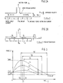
- a stack comprising alternate layers of green sheet material and spacers is moved upward toward the pick-up head at a stack approach velocity v. That is, the stack approaches the head at a given velocity and is then stopped in a position where the top greer
- the head may fail to pick up a sheet due to an insufficient attraction force.
- the attraction force which is a function of system parameters such as stack approach velocity, v, dwell time of the stack in proximity to the pick-up head, sheet flexibility, and the true surface spacing in the contact position.
- true surface spacing this parameter refers to the precision in stopping the stack at a predetermined head-stack spacing, h, as shown in Fig. lA, the texture of the green sheet material and the like.
- a prime consideration is the pumping effectiveness at the head surface. This parameter is a function of the number, size, shape, and arrangement of the suction ports, vis-a-vis the "true" spacing in the dwell period.
- Fig. 2A provides a force diagram showing the condition where equilibrium is not attained such that the green sheet will not be held by the head, while, Fig. 2B shows the force conditions necessary to establish pick up.
- Fig. 3 plots force F as a function of time and, for a given pumping effectiveness, the plots demonstrate that the force on the sheet characteristically goes through a maximum force value followed by a steady decrease to a minimum value or is equal to the sheet weight.
- t f is the travel time and t d , is the dwell time at the pick-up condition height h f .
- the curves establish the relationship v 1 ⁇ v 2 ⁇ v 3 .
- the present invention is related to a different technique of achieving lifting by creating a suction field.
- the present invention does not require a vacuum source but rather is based on the recognition that the aspiration properties of the gas jet provide the necessary force characteristics to uniformly and gently lift and holdiflat delicate objects, such as green sheets.
- the aggregate aspiration effects are manifested as a suction effect at the lower surface of the pick-up device. Consequently, when a green sheet is placed in proximity to this surface, it will be attracted and held in place.
- FIG 4 streamlines of a free jet issuing into the atmosphere are shown.
- a supply orifice 10 produces an air jet having a flow path substantially perpendicular to a wall portion 12.
- the air issuing from the jet may be either laminar or turbulent.
- Flow lines created by aspirated flow are generated as shown in Figure 4. That is, due to entrainment of the issuing air jet, streamlines are created which are directed inwardly and generally parallel to the wall surface 12 and then define streamlines generally parallel to the air jet. Flow rates tend to increase in the axial direction.
- a typical velocity profile (normal to the axial direction) is shown in Figure 4 for the air jets and the aspirated air flow.
- a free air jet issuing into the atmosphere characteristically entrains surrounding air. This flow condition can be used by confining the jet on three sides to focus the aspiration effect into a slot region.
- FIG. 5 illustrating one embodiment of this invention.
- An orifice 10 receives a supply of air and discharges it into a slot 14.
- This embodiment shows a single slot system.
- the slot has three wall surfaces and an opening defining a suction slot. Due to aspirated air flow into the slot, a suction region occurs. The entraining or aspiration effect is therefore focused into the slot region which exists over a large portion of the slot. The magnitude and extent of the suction are a function of the slot geometry and supply flow conditions.
- the slot 14 is elongate and straight. The elongate dimension relative to slot width is necessary to achieve steady state aspiration. A series of ports, each discrete over the same slot length would not achieve steady state conditions.
- the slot edges 15 are shown to be sharp, orthogonal to the slot openings. Improved flow characteristics may be achieved by radiusing these edges to promote laminar flow around the corner.
- the slot need not be straight. In some applications a curved or sinuous slot may be employed.
- FIGs. 6A, 6B, 6C, and 6D illustrate a second embodiment of the present invention.
- This embodiment utilizes two components, a plate 20 having the air supply flow and nozzle 10 and a plenum 22.
- the second member 30 contains a series of slots 32 positioned radially outward from the bottom surface and in fluid communication with the plenum 22 by means of a network of feed orifices 34.
- a bottom plan view each pair of slots 32 is coupled to the plenum 22 by a single feed orifice 34.
- the plenum in turn is coupled to the supply flow by means of the nozzle 10.
- Members 20 and 30, generally metallic, are coupled together at their corners by any conventional coupling elements 36.
- a series of parallel slots 32 and orifice feed grooves 34 are machined into that member.
- the number and placement of the slots 32 is a function of the ultimate utilization of the device vis-a-vis the material to be handled.
- the top member 20 contains the plenum and flow supply port with the two members attached as shown in Fig. 6B.
- Gas under pressure is then supplied from nozzle 10 into the plenum 22. It is fed via the feed orifices 34 into the slots where, as shown in Fig. 6A, a slotted flow jet emanates. As shown in Figures 5B and 5C, the slot jets 32, as a result of aspiration, tend to generate a suction effect. Accordingly, a surface placed generally parallel to the end wall 12 will be attacted and held at that surface.
- the device of Figures 6A-6D can be operated over a wide range of flow supply pressures. It is capable of effectively picking up and holding flexible as well as rigid materials. For example, at a supply pressure of approximately 0,28 bar, materials such as tissue paper, cloth or wafers are easily attracted and held by the transfer head. At the same time, flow consumption requirements are modest because of the small feed groove dimensions. Inherently, the pumping action of the slots produces a more extensive suction action due to the flow behavior in the slot regions. Hence, wider variations in sheet-head positioning can be tolerated without adverse effects on performance. Stated differently, accurate registration between the green sheet supply and the pick-up head is more readily tolerated in the device in accordance with the embodiment shown in Figures 6A-6D.
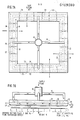
- FIG. 7A A third preferred embodiment of this invention is shown in Figures 7A and 7B.
- This configuration of a green sheet pick-up head utilizes the same aspirator jet suction techniques of the Figure 6 embodiment in the context of a larger pick-up head configuration.
- a supply from nozzle 10 is directed into a feed manifold which comprises four segments each feeding air into portions of the pick-up head having a plenum 22.
- the plenum 22 extends circumferentially about the device wherein each segment comprises a top member 20 and a bottom member 30.
- a series of radially directed slots 32 radiate from the plenum 22 in a manner corresponding to that of the embodiment of Figure 6 each pair of slots being coupled to the plenum 22 by a single feed orifice.
- a slot jet flow therefore emanates from the slots 32 in a manner corresponding to the prior embodiment.
- corner portions of member 30 are beveled at surfaces 24 to tailor the extent of the surface in contact with the green sheet. That is, the bottom surface 12 is selectively varied by the extent of the bevel 24 on both sides of the lower surface 12. Consequently, the amount of green sheet surface area which contacts surface 12 can be optimized as a function of that bevel.
- the corners of each slot may be radiused to improve flow characteristics.
- Fig. 7B shows an average suction force F which is due to the aspiration effect of air released by the slots 32. When that force equals and counteracts the weight of the green sheet, the sheet is attached to the head, that is, attached to surface 12.
- Figures 7A and 7B illustrates a symmetrical manifold arrangement from a common inlet source. Consequently, air issuing from the multiple slots 32 generates a suction which attracts in a uniform manner the approaching sheet to the surface 12. Given the sensitive nature of the green sheet material, the beveling construction, while not affecting the suction operation of the device, allows minimum yet effective contact to occur.
- the focused aspiration flow characteristics of a partially enclosed gas jet move parallel to the planar surface of a flexible sheet.
- This flow condition manifests itself as a continuously generated suction effect in the region bounded by the slot and sheet surfacels.
- the parallel gas stream induces a boundary layer frictional force on the sheet acting in the direction of the flow.
- the slots need not be directed radially outward, but as pick-up conditions dictate, be offset or skewed vis-a-vis the center of the pick-up head. Also, since the invention finds application for use with flexible materials, it is apparent that it can be employed to lift rigid wafers.
Landscapes
- Sheets, Magazines, And Separation Thereof (AREA)
- Delivering By Means Of Belts And Rollers (AREA)
- Feeding Of Articles By Means Other Than Belts Or Rollers (AREA)
- Load-Engaging Elements For Cranes (AREA)
Applications Claiming Priority (2)
| Application Number | Priority Date | Filing Date | Title |
|---|---|---|---|
| US06/442,206 US4474397A (en) | 1982-11-16 | 1982-11-16 | Pick-up head utilizing aspirated air flow |
| US442206 | 1982-11-16 |
Publications (2)
| Publication Number | Publication Date |
|---|---|
| EP0109080A1 true EP0109080A1 (de) | 1984-05-23 |
| EP0109080B1 EP0109080B1 (de) | 1987-07-22 |
Family
ID=23755925
Family Applications (1)
| Application Number | Title | Priority Date | Filing Date |
|---|---|---|---|
| EP83111346A Expired EP0109080B1 (de) | 1982-11-16 | 1983-11-14 | Aufnahmekopf zum Bewegen von blattförmigem Material |
Country Status (4)
| Country | Link |
|---|---|
| US (1) | US4474397A (de) |
| EP (1) | EP0109080B1 (de) |
| JP (1) | JPS5992545A (de) |
| DE (1) | DE3372681D1 (de) |
Cited By (7)
| Publication number | Priority date | Publication date | Assignee | Title |
|---|---|---|---|---|
| DE3536432A1 (de) * | 1985-10-12 | 1987-04-16 | Telefunken Electronic Gmbh | Beruehrungslose haltevorrichtung fuer halbleiterscheiben |
| DE3920035A1 (de) * | 1988-07-04 | 1990-01-11 | Kuttler Hans Juergen | Vorrichtung zum vereinzeln und transportieren von werkstuecken |
| AT1527U1 (de) * | 1995-07-12 | 1997-06-25 | Sez Semiconduct Equip Zubehoer | Träger für scheibenförmige gegenstände, insbesondere siliziumscheiben |
| WO1999046199A1 (en) * | 1998-03-13 | 1999-09-16 | Ab Initio | Vacuum ejector with a number of suction cups |
| US6022417A (en) * | 1995-07-12 | 2000-02-08 | Sumnitsch; Franz | Support for wafer-shaped objects, in particular silicon wafers |
| DE102009047086A1 (de) * | 2009-11-24 | 2011-05-26 | J. Schmalz Gmbh | Druckluftbetriebener Greifer |
| JP2024504089A (ja) * | 2021-01-11 | 2024-01-30 | 中国石油化工股▲ふん▼有限公司 | 炭化水素から低炭素オレフィンを製造するための流動化接触転換方法 |
Families Citing this family (14)
| Publication number | Priority date | Publication date | Assignee | Title |
|---|---|---|---|---|
| US5067762A (en) * | 1985-06-18 | 1991-11-26 | Hiroshi Akashi | Non-contact conveying device |
| DE3822597A1 (de) * | 1988-07-04 | 1990-01-11 | Siemens Ag | Justiervorrichtung und verfahren zum justieren eines roboterarms zum einsatz in automatisierten produktionsbereichen insbesondere in der halbleitertechnik |
| US5470420A (en) * | 1992-07-31 | 1995-11-28 | Eastman Kodak Company | Apparatus for label application using Bernoulli Effect |
| US6455186B1 (en) | 1998-03-05 | 2002-09-24 | Black & Decker Inc. | Battery cooling system |
| US6095582A (en) * | 1998-03-11 | 2000-08-01 | Trusi Technologies, Llc | Article holders and holding methods |
| GB9822153D0 (en) * | 1998-10-09 | 1998-12-02 | Labflax Systems Ltd | Apparatus for applying labels to moving articles |
| JP4391655B2 (ja) | 2000-02-22 | 2009-12-24 | インターナショナル・ビジネス・マシーンズ・コーポレーション | エアピンセット |
| US7007942B1 (en) | 2003-03-25 | 2006-03-07 | Wps Industries, Inc. | Panel handling apparatus |
| JP3703464B2 (ja) * | 2003-04-04 | 2005-10-05 | キヤノン株式会社 | マニピュレータ |
| EP2411191B1 (de) * | 2009-03-26 | 2013-08-28 | Jonas & Redmann Automationstechnik GmbH | Bernoulli-greifervorrichtung mit mindestens einem bernoulli-greifer |
| US9490156B2 (en) * | 2013-05-23 | 2016-11-08 | Asm Technology Singapore Pte Ltd | Transfer device for holding an object using a gas flow |
| US10398070B2 (en) * | 2015-02-17 | 2019-08-27 | Fuji Corporation | Suction nozzle |
| JP6651327B2 (ja) * | 2015-10-15 | 2020-02-19 | 東レエンジニアリング株式会社 | シート材のエアフロート装置 |
| JP2018122381A (ja) * | 2017-01-31 | 2018-08-09 | ブラザー工業株式会社 | 部品保持装置 |
Citations (8)
| Publication number | Priority date | Publication date | Assignee | Title |
|---|---|---|---|---|
| US3411770A (en) * | 1966-08-04 | 1968-11-19 | Sperry Rand Corp | Sheet separator |
| US3523706A (en) * | 1967-10-27 | 1970-08-11 | Ibm | Apparatus for supporting articles without structural contact and for positioning the supported articles |
| US3539216A (en) * | 1968-01-11 | 1970-11-10 | Sprague Electric Co | Pickup device |
| US3648853A (en) * | 1970-04-03 | 1972-03-14 | Erie Eng Co | Vacuum work pick-up attachment for work device |
| US4029351A (en) * | 1976-06-02 | 1977-06-14 | International Business Machines Corporation | Bernoulli pickup head with self-restoring anti-tilt improvement |
| DE2524916B2 (de) * | 1975-06-05 | 1978-03-16 | Reifenhaeuser Kg, 5210 Troisdorf | Greifvorrichtung für feste Körper |
| US4185814A (en) * | 1977-12-12 | 1980-01-29 | International Business Machines Corporation | Pick up and placement head for green sheet and spacer |
| US4257637A (en) * | 1979-09-28 | 1981-03-24 | International Business Machines Corporation | Contactless air film lifting device |
Family Cites Families (4)
| Publication number | Priority date | Publication date | Assignee | Title |
|---|---|---|---|---|
| JPS5420963Y2 (de) * | 1974-07-16 | 1979-07-27 | ||
| GB1513444A (en) * | 1974-09-06 | 1978-06-07 | Chemical Reactor Equip As | Pick-up devices for lifting and moving semiconductor wafers |
| JPS56156580U (de) * | 1980-04-18 | 1981-11-21 | ||
| JPS58141536A (ja) * | 1982-02-17 | 1983-08-22 | Sanyo Electric Co Ltd | 半導体ウエハ−の吸着ヘツド |
-
1982
- 1982-11-16 US US06/442,206 patent/US4474397A/en not_active Expired - Lifetime
-
1983
- 1983-10-11 JP JP58188583A patent/JPS5992545A/ja active Granted
- 1983-11-14 EP EP83111346A patent/EP0109080B1/de not_active Expired
- 1983-11-14 DE DE8383111346T patent/DE3372681D1/de not_active Expired
Patent Citations (8)
| Publication number | Priority date | Publication date | Assignee | Title |
|---|---|---|---|---|
| US3411770A (en) * | 1966-08-04 | 1968-11-19 | Sperry Rand Corp | Sheet separator |
| US3523706A (en) * | 1967-10-27 | 1970-08-11 | Ibm | Apparatus for supporting articles without structural contact and for positioning the supported articles |
| US3539216A (en) * | 1968-01-11 | 1970-11-10 | Sprague Electric Co | Pickup device |
| US3648853A (en) * | 1970-04-03 | 1972-03-14 | Erie Eng Co | Vacuum work pick-up attachment for work device |
| DE2524916B2 (de) * | 1975-06-05 | 1978-03-16 | Reifenhaeuser Kg, 5210 Troisdorf | Greifvorrichtung für feste Körper |
| US4029351A (en) * | 1976-06-02 | 1977-06-14 | International Business Machines Corporation | Bernoulli pickup head with self-restoring anti-tilt improvement |
| US4185814A (en) * | 1977-12-12 | 1980-01-29 | International Business Machines Corporation | Pick up and placement head for green sheet and spacer |
| US4257637A (en) * | 1979-09-28 | 1981-03-24 | International Business Machines Corporation | Contactless air film lifting device |
Non-Patent Citations (6)
| Title |
|---|
| IBM TECHNICAL DISCLOSURE BULLETIN, vol. 11, no. 2, July 1968 *C.P. HAYUNGA "WAFER PICKUP WITH AIR BARRIER" PAGE 112* * |
| IBM TECHNICAL DISCLOSURE BULLETIN, vol. 17, no. 1, June 1974 *R.H. BRUNNER "WAFER CHUCK" PAGE 84 * * |
| IBM TECHNICAL DISCLOSURE BULLETIN, vol. 18, no. 6, November 1975 *H. VON BURG ET AL: "ORIENTING BERNOULLI EFFECT WAFER TRANSFER MECHANISM" PAGES 1836, 1837 * * |
| IBM TECHNICAL DISCLOSURE BULLETIN, vol. 18, no. 8, January 1976 *R.F. BOUDAH; A:C: KEY "WAFER SENSING BERNOULLI HEAD "PAGE 2447 * * |
| IBM TECHNICAL DISCLOSURE BULLETIN, vol. 20, no. 2, July 1977 *B.C. O'NEILL ET AL. "ANNULAR ORIENTOR" PAGES 593, 594 * * |
| IBM TECHNICAL DISCLOSURE BULLETIN, vol. 22, no. 5, October 1979 3W:B:BALDER; R,P, CACHON "DIVERTED FLOW BERNOULLI PICK UP DEVICE " PAGES 1864,1865 * * |
Cited By (9)
| Publication number | Priority date | Publication date | Assignee | Title |
|---|---|---|---|---|
| DE3536432A1 (de) * | 1985-10-12 | 1987-04-16 | Telefunken Electronic Gmbh | Beruehrungslose haltevorrichtung fuer halbleiterscheiben |
| DE3920035A1 (de) * | 1988-07-04 | 1990-01-11 | Kuttler Hans Juergen | Vorrichtung zum vereinzeln und transportieren von werkstuecken |
| AT1527U1 (de) * | 1995-07-12 | 1997-06-25 | Sez Semiconduct Equip Zubehoer | Träger für scheibenförmige gegenstände, insbesondere siliziumscheiben |
| US6022417A (en) * | 1995-07-12 | 2000-02-08 | Sumnitsch; Franz | Support for wafer-shaped objects, in particular silicon wafers |
| WO1999046199A1 (en) * | 1998-03-13 | 1999-09-16 | Ab Initio | Vacuum ejector with a number of suction cups |
| US6467825B1 (en) | 1998-03-13 | 2002-10-22 | Pronomic Ab | Vacuum ejector with a number of suction cups |
| DE102009047086A1 (de) * | 2009-11-24 | 2011-05-26 | J. Schmalz Gmbh | Druckluftbetriebener Greifer |
| JP2024504089A (ja) * | 2021-01-11 | 2024-01-30 | 中国石油化工股▲ふん▼有限公司 | 炭化水素から低炭素オレフィンを製造するための流動化接触転換方法 |
| JP7746389B2 (ja) | 2021-01-11 | 2025-09-30 | 中国石油化工股▲ふん▼有限公司 | 炭化水素から低炭素オレフィンを製造するための流動化接触転換方法 |
Also Published As
| Publication number | Publication date |
|---|---|
| US4474397A (en) | 1984-10-02 |
| JPS5992545A (ja) | 1984-05-28 |
| JPH0353777B2 (de) | 1991-08-16 |
| DE3372681D1 (en) | 1987-08-27 |
| EP0109080B1 (de) | 1987-07-22 |
Similar Documents
| Publication | Publication Date | Title |
|---|---|---|
| EP0109080B1 (de) | Aufnahmekopf zum Bewegen von blattförmigem Material | |
| US5067762A (en) | Non-contact conveying device | |
| KR100675408B1 (ko) | 들기 장치 | |
| CN102753312B (zh) | 批量传输薄基片的伯努利式端拾器 | |
| US5169196A (en) | Non-contact pick-up head | |
| KR100859835B1 (ko) | 비접촉식 진공패드 | |
| CN103219271B (zh) | 吸引夹持器及移载装置 | |
| KR100478335B1 (ko) | 시이트적층물의최상위시이트분리이송장치 | |
| KR102315301B1 (ko) | 반송 패드 및 웨이퍼의 반송 방법 | |
| KR101261313B1 (ko) | 평판 이송물 정렬픽업 이송장치 | |
| KR20120042507A (ko) | 래디얼 플로우를 이용한 비접촉식 기판 척킹용 에어 패드 | |
| US6647791B1 (en) | Device for contactlessly gripping and positioning components | |
| JP3445138B2 (ja) | 無接触搬送装置 | |
| JP5384305B2 (ja) | ワーク搬送装置 | |
| JPH0151413B2 (de) | ||
| JP7456399B2 (ja) | シート搬送装置 | |
| JP2002280439A (ja) | 搬送装置 | |
| JP6716136B2 (ja) | 流体流形成体及び非接触搬送装置 | |
| JPH05335404A (ja) | 無接触保持装置 | |
| JPH11198080A (ja) | 吸引保持ユニット、吸引保持ブロック、および吸引保持機構 | |
| US6981312B2 (en) | System for handling microelectronic dies having a non-piercing die ejector | |
| JP2697013B2 (ja) | クランプ装置 | |
| JPS61111251A (ja) | 平板状部材の保持装置 | |
| JPS61206744A (ja) | 真空吸引チヤツク | |
| CN120229485A (zh) | 非接触手持搬运装置 |
Legal Events
| Date | Code | Title | Description |
|---|---|---|---|
| PUAI | Public reference made under article 153(3) epc to a published international application that has entered the european phase |
Free format text: ORIGINAL CODE: 0009012 |
|
| AK | Designated contracting states |
Designated state(s): DE FR GB |
|
| 17P | Request for examination filed |
Effective date: 19840921 |
|
| GRAA | (expected) grant |
Free format text: ORIGINAL CODE: 0009210 |
|
| AK | Designated contracting states |
Kind code of ref document: B1 Designated state(s): DE FR GB |
|
| REF | Corresponds to: |
Ref document number: 3372681 Country of ref document: DE Date of ref document: 19870827 |
|
| ET | Fr: translation filed | ||
| PLBE | No opposition filed within time limit |
Free format text: ORIGINAL CODE: 0009261 |
|
| STAA | Information on the status of an ep patent application or granted ep patent |
Free format text: STATUS: NO OPPOSITION FILED WITHIN TIME LIMIT |
|
| 26N | No opposition filed | ||
| PGFP | Annual fee paid to national office [announced via postgrant information from national office to epo] |
Ref country code: GB Payment date: 19931019 Year of fee payment: 11 |
|
| PGFP | Annual fee paid to national office [announced via postgrant information from national office to epo] |
Ref country code: FR Payment date: 19931103 Year of fee payment: 11 |
|
| PGFP | Annual fee paid to national office [announced via postgrant information from national office to epo] |
Ref country code: DE Payment date: 19931118 Year of fee payment: 11 |
|
| PG25 | Lapsed in a contracting state [announced via postgrant information from national office to epo] |
Ref country code: GB Effective date: 19941114 |
|
| GBPC | Gb: european patent ceased through non-payment of renewal fee |
Effective date: 19941114 |
|
| PG25 | Lapsed in a contracting state [announced via postgrant information from national office to epo] |
Ref country code: FR Effective date: 19950731 |
|
| PG25 | Lapsed in a contracting state [announced via postgrant information from national office to epo] |
Ref country code: DE Effective date: 19950801 |
|
| REG | Reference to a national code |
Ref country code: FR Ref legal event code: ST |