EP0103044B1 - Verfahren zur Herstellung von Ringformkörpern, insbesondere Synchronringrohlingen - Google Patents
Verfahren zur Herstellung von Ringformkörpern, insbesondere Synchronringrohlingen Download PDFInfo
- Publication number
- EP0103044B1 EP0103044B1 EP82108492A EP82108492A EP0103044B1 EP 0103044 B1 EP0103044 B1 EP 0103044B1 EP 82108492 A EP82108492 A EP 82108492A EP 82108492 A EP82108492 A EP 82108492A EP 0103044 B1 EP0103044 B1 EP 0103044B1
- Authority
- EP
- European Patent Office
- Prior art keywords
- flat wire
- produced
- bent
- hard materials
- ring body
- Prior art date
- Legal status (The legal status is an assumption and is not a legal conclusion. Google has not performed a legal analysis and makes no representation as to the accuracy of the status listed.)
- Expired
Links
- 238000000034 method Methods 0.000 title claims abstract description 11
- 229910001369 Brass Inorganic materials 0.000 claims abstract description 8
- 239000010951 brass Substances 0.000 claims abstract description 8
- 239000000463 material Substances 0.000 claims abstract description 7
- 238000004519 manufacturing process Methods 0.000 claims abstract description 5
- 239000011265 semifinished product Substances 0.000 claims abstract description 3
- 238000003754 machining Methods 0.000 claims abstract 2
- 238000003466 welding Methods 0.000 claims description 5
- 229910021332 silicide Inorganic materials 0.000 description 7
- 238000001125 extrusion Methods 0.000 description 5
- 238000005520 cutting process Methods 0.000 description 3
- 239000002699 waste material Substances 0.000 description 3
- 238000005096 rolling process Methods 0.000 description 2
- 238000007493 shaping process Methods 0.000 description 2
- 229910002535 CuZn Inorganic materials 0.000 description 1
- 229910045601 alloy Inorganic materials 0.000 description 1
- 239000000956 alloy Substances 0.000 description 1
- 238000005452 bending Methods 0.000 description 1
- 230000000694 effects Effects 0.000 description 1
- 238000000227 grinding Methods 0.000 description 1
- 238000001192 hot extrusion Methods 0.000 description 1
- 239000002184 metal Substances 0.000 description 1
- 239000000203 mixture Substances 0.000 description 1
- 238000003825 pressing Methods 0.000 description 1
- 238000000926 separation method Methods 0.000 description 1
- 230000001360 synchronised effect Effects 0.000 description 1
Images
Classifications
-
- B—PERFORMING OPERATIONS; TRANSPORTING
- B21—MECHANICAL METAL-WORKING WITHOUT ESSENTIALLY REMOVING MATERIAL; PUNCHING METAL
- B21F—WORKING OR PROCESSING OF METAL WIRE
- B21F37/00—Manufacture of rings from wire
-
- B—PERFORMING OPERATIONS; TRANSPORTING
- B21—MECHANICAL METAL-WORKING WITHOUT ESSENTIALLY REMOVING MATERIAL; PUNCHING METAL
- B21D—WORKING OR PROCESSING OF SHEET METAL OR METAL TUBES, RODS OR PROFILES WITHOUT ESSENTIALLY REMOVING MATERIAL; PUNCHING METAL
- B21D53/00—Making other particular articles
- B21D53/16—Making other particular articles rings, e.g. barrel hoops
-
- F—MECHANICAL ENGINEERING; LIGHTING; HEATING; WEAPONS; BLASTING
- F16—ENGINEERING ELEMENTS AND UNITS; GENERAL MEASURES FOR PRODUCING AND MAINTAINING EFFECTIVE FUNCTIONING OF MACHINES OR INSTALLATIONS; THERMAL INSULATION IN GENERAL
- F16D—COUPLINGS FOR TRANSMITTING ROTATION; CLUTCHES; BRAKES
- F16D23/00—Details of mechanically-actuated clutches not specific for one distinct type
- F16D23/02—Arrangements for synchronisation, also for power-operated clutches
- F16D23/025—Synchro rings
Definitions
- the invention relates to a method for producing shaped synchronizer rings according to the preamble of claim 1. Such a method is state of the art.
- a tube made of special brass is shaped by hot extrusion to the dimensions (diameter, wall thickness) of the synchronizer ring blank. Disc-shaped blanks are then separated from the tube, from which synchronizer rings are forged.
- This process has several disadvantages. Due to unmanageable extrusion errors, e.g. B. doublings, bubbles, overlaps, are known to result in extruded tube and here in particular at the tube ends, considerable waste (waste). In addition, there is further waste, which results in particular when the blanks are cut from the tube, so that overall only a small part of the extrusion billet used and thus of the extruded tube can be processed as a blank to form synchronous rings.
- the wear resistance of the synchronizer rings is brought about by rod-shaped silicides.
- these wear-reducing silicides are arranged by the shape with their longitudinal axis in the longitudinal direction (axial) of the wall of the tube. This is of considerable disadvantage, since in this way the longitudinal axis of the silicides is arranged transversely to the direction of wear during later use of the synchronizer rings in operation, so that only a small part of the wear-reducing properties comes into play.
- the invention is therefore based on the object of providing a method of the type mentioned at the outset which permits more economical use of materials and allows the production of shaped synchronizer rings with improved wear-reducing action.
- a flat wire with the dimensions (cross-sectional width and height) of the blank can be cut by non-cutting, z. B. extrusion, rolling, are produced in a very economical manner. For example, special brass can be easily formed.
- One advantage is the production of a semi-finished product with a full cross section. For example, there are no pressing errors.
- the blend z. B. for material return can be limited to approx. 5%.
- the flat wire is subjected to a bending process by means of which the round shape of the blank is adjusted. Finally, the two ends (butt edges, cut edges) of the flat wire are connected to each other.
- a particular advantage is that the sicilides are arranged with their longitudinal direction in the forming direction during the non-cutting shaping.
- the silicides are also arranged in the blank and thus in the synchronizer ring in the circumferential direction (tangential) and thus in the direction of the friction, so that an optimal wear-reducing effect is thereby achieved.
- the flat wire is cut to sections before the bend, the length of which corresponds to the circumferential length of the blanks.
- Such a subdivision can advantageously be achieved by cutting, e.g. B. sawing, grinding.
- the flat wire is cut to length after the bend.
- the flat wire can first be wound around a core, the outside diameter of which corresponds to the inside diameter of the blank. This can be done at high speed. Then by a separation, for. B. made a longitudinal section from the outside through the coiled coils of the flat wire at one point on its circumference open rings, the open ends are finally connected.
- the coils can also first be stripped from the core and then separated by sawing, which creates the annular blanks that are open at one point.
- the flat wire is produced in a particularly economical way by extrusion. However, it can also be advantageous to produce the flat wire by rolling, for example to produce a cross-sectional profile.
- the ends are preferably by pressure welding, for. B. HF welding, connected (claim 3) because this eliminates the use of different welding material.
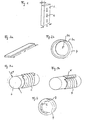
- Figure 1 shows a flat wire 1 with a width (b) of 10 mm and a height (h) of 5 mm, the z. B. was produced by extrusion.
- 2 denotes silicides, the longitudinal direction of which is oriented in the longitudinal direction of the flat wire during the shaping.
- a section 3 of a length (1) of the flat wire 1 is sawn by sawing 250 mm have been cut off, the length (1) corresponding to the circumference of the synchronizer ring blank.
- the section 3 is bent according to Figure 2b to a ring 4 in a conventional manner, between the ends 4a, 4b there is an open space 5.
- FIG. 3a shows a cylindrical core 6, the outside diameter (d) of which corresponds to the inside diameter (d) of the circular blank.
- the flat wire 1 is wound tightly around this core 6 and thereby bent.
- 3b a longitudinal section is then sawn into the coils of the flat wire, as a result of which the rings 4 are formed with the open interspace 5.
- the ends 4a, 4b are connected to the weld metal 7 by filling the intermediate space 5, so that the synchronizer ring blank 4 is produced in this way.
- Figure 4 is also shown schematically that the longitudinal direction of the silicides in the circumferential direction (tangential) of the ring body 4 (synchronizer ring blank) are arranged.
- the ring body 4 has an outer diameter D of 80 mm.
- a CuZn 40 AI 2 alloy can be used as a special brass.
- B. Mn and Si can be alloyed.
Landscapes
- Engineering & Computer Science (AREA)
- Mechanical Engineering (AREA)
- General Engineering & Computer Science (AREA)
- Mechanical Operated Clutches (AREA)
- Rolling Contact Bearings (AREA)
- Wire Processing (AREA)
Description
- Die Erfindung betrifft ein Verfahren zur Herstellung von Synchronringformkörpern gemäß Oberbegriff von Anspruch 1. Ein solches Verfahren ist Stand der Technik.
- Bei diesem bekannten Verfahren wird ein Rohr aus Sondermessing durch Warmstrangpressen auf die Abmessungen (Durchmesser, Wandstärke) des Synchronringrohlings umgeformt. Anschließend werden von dem Rohr scheibenförmige Rohlinge abgetrennt, aus denen Synchronringe geschmiedet werden. Dieses Verfahren weist mehrere Nachteile auf. Aufgrund nicht beherrschbarer Strangpreßfehler, z. B. Dopplungen, Blasen, Überlappungen, ergeben sich bekanntlich am stranggepreßten Rohr und hier insbesondere an den Rohrenden, erhebliche Abfälle (Verschnitt). Hinzu kommt weiterer Verschnitt, der sich insbesondere bei spanendem Abtrennen der Rohlinge vom Rohr ergibt, so daß insgesamt nur ein geringer Teil des eingesetzten Strangpreßbarrens und damit des stranggepreßten Rohres als Rohling zu Synchronringen verarbeitet werden kann. Die Verschleißfestigkeit der Synchronringe wird bei Verwendung von Sondermessing durch stäbchenförmig ausgeschiedene Silizide herbeigeführt. Bei dem bekannten Verfahren ordnen sich diese verschleißmindernden Silizide durch die Formgebung mit ihrer Längsachse in Längsrichtung (axial) der Wand des Rohres an. Dies ist von erheblichem Nachteil, da auf diese Weise die Längsachse der Silizide quer zur Richtung der Verschleißbeanspruchung während des späteren Einsatzes der Synchronringe im Betrieb angeordnet wird, so daß nur ein geringer Teil der verschleißmindernden Eigenschaften zum Tragen kommt.
- Der Erfindung liegt daher die Aufgabe zugrunde, ein Verfahren der eingangs genannten Art zu schaffen, das eine wirtschaftlichere Materialverwertung gestattet und die Herstellung von Synchronringformkörpern mit verbesserter verschieißmindernder Wirkung erlaubt.
- Die Lösung dieser Aufgabe erfolgt durch die kennzeichnenden Merkmale des Anspruchs 1.
- Ein Flachdraht mit den Abmessungen (Querschnittsbreite und -höhe) des Rohlings kann durch spanlose Formgebung, z. B. Strangpressen, Walzen, auf sehr wirtschaftliche Weise hergestellt werden. Beispielsweise läßt sich Sondermessing leicht umformen. Ein Vorteil besteht in der Herstellung eines Halbzeugs mit einem Vollquerschnitt. Dabei treten beispielsweise keine Preßfehler auf. Der Verschnitt z. B. für Materialrücklauf kann auf ca. 5 % begrenzt werden. Der Flachdraht wird einem Biegevorgang unterworfen, durch den die runde Form des Rohlings eingestellt wird. Schließlich werden die beiden Enden (Stoßkanten, Schnittkanten) des Flachdrahtes miteinander verbunden. Ein besonderer Vorteil besteht dabei darin, daß sich die Sizilide bei der spanlosen Formgebung mit ihrer Längsrichtung in der Umformrichtung anordnen.
- Dadurch sind die Silizide auch im Rohling und damit im Synchronring in Umfangsrichtung (tangential) und damit in Richtung der Reibung angeordnet, so daß dadurch eine optimal verschieißmindernde Wirkung verwirklicht ist.
- Vorzugsweise wird der Flachdraht vor der Biegung in Abschnitte abgelängt, deren Länge der Umfangslänge der Rohlinge entspricht Anspruch 2. Eine solche Unterteilung kann vorteilhaft durch spanende Trennung, z. B. Sägen, Schleifen, erfolgen. Nach einer weiteren bevorzugten Ausführungsform wird der Flachdraht nach der Biegung abgelängt. Dabei kann der Flachdraht zunächst um einen Kern gewickelt werden, dessen Außendurchmesser dem Innendurchmesser des Rohlings entspricht. Dieser Vorgang kann mit hoher Geschwindigkeit vorgenommen werden. Anschließend werden durch eine Trennung, z. B. einen Längsschnitt von außen durch die aufgewickelten Wendeln des Flachdrahtes an einer Stelle ihres Umfangs offene Ringe hergestellt, deren offene Enden schließlich verbunden werden. Die Wendeln können auch erst von Kern abgestreift und dann durch Sägen getrennt werden, wodurch die an einer Stelle offenen ringförmigen Rohlinge entstehen. Der Flachdraht wird auf besonders wirtschaftliche Weise durch Strangpressen hergestellt. Es kann aber auch vorteilhaft sein, den Flachdraht durch Walzen herzustellen, beispielsweise zur Erzeugung einer Querschnittsprofilierung. Zweckmäßig werden die Enden des gebogenen Flachdrahtes, z. B. die Schnittkanten, auf wirtschaftliche Weise durch Schweißen miteinander verbunden. Bevorzugt werden die Enden durch Preßschweißen, z. B. HF-Schweißen, verbunden (Anspruch 3), weil dadurch die Verwendung andersartigen Schweißmaterials entfällt.
- Die Erfindung wird nachfolgend anhand von zeichnerisch dargestellten Ausführungsbeispielen näher erläutert.
- Es zeigt :
- Figur 1 einen Flachdraht mit schematischer Darstellung der eingelagerten Silizide,
- Figur 2a einen abgelängten, geraden Flachdraht,
- Figur 2b den Flachdraht nach Fig. 2a in gebogenem Zustand,
- Figur 3a einen um einen Kern gewickelten Flachdraht,
- Figur 3b den Flachdraht nach Fig. 3a in abgelängtem Zustand und
- Figur 4 einen Synchronringrohling mit Schweißnaht.
- Figur 1 zeigt einen Flachdraht 1 mit einer Breite (b) von 10 mm und einer Höhe (h) von 5 mm, der z. B. durch Strangpressen hergestellt wurd. Mit 2 sind Silizide bezeichnet, deren Längsrichtung beim Umformen in Längsrichtung des Flachdrahtes ausgerichtet werden.
- Nach Figur 2a ist von dem Flachdraht 1 durch Sägen ein Teilstück 3 mit einer Länge (1) von 250 mm abgetrennt worden, wobei die Länge (1) dem Umfang des Synchronringrohlings entspricht.
- Das Teilstück 3 ist nach Figur 2b zu einem Ring 4 auf an sich bekannte Weise gebogen, zwischen dessen Enden 4a, 4b ein offener Zwischenraum 5 vorhanden ist.
- Figur 3a zeigt einen zylindrischen Kern 6, dessen Aussendurchmesser (d) dem Innendurchmesser (d) des Kreisringrohlings entspricht. Um diesen Kern 6 wird der Flachdraht 1 eng gewickelt und dadurch gebogen. Anschließend wird nach Figur 3b von außen in die Wendeln des Flachdrahtes ein Längsschnitt eingesägt, wodurch die Ringe 4 mit dem offenen Zwischenraum 5 gebildet werden.
- Schließlich werden nach Figur 4 die Enden 4a, 4b durch Auffüllen des Zwischenraumes 5 mit Schweißgut 7 verbunden, so daß auf diese Weise der Synchronringrohling 4 entsteht. In Figur 4 ist außerdem schematisch dargestellt, daß die Längsrichtung der Silizide in Umfangsrichtung (tangential) des Ringkörpers 4 (Synchronringrohling) angeordnet sind. Der Ringkörper 4 hat einen Außendurchmesser D von 80 mm.
- Als Sondermessing kann beispielsweise eine CuZn 40 AI 2 - Legierung verwendet werden, der z. B. Mn und Si zulegiert sein können.
Claims (3)
Priority Applications (3)
| Application Number | Priority Date | Filing Date | Title |
|---|---|---|---|
| AT82108492T ATE19970T1 (de) | 1982-09-15 | 1982-09-15 | Verfahren zur herstellung von ringformkoerpern, insbesondere synchronringrohlingen. |
| EP82108492A EP0103044B1 (de) | 1982-09-15 | 1982-09-15 | Verfahren zur Herstellung von Ringformkörpern, insbesondere Synchronringrohlingen |
| DE8282108492T DE3271387D1 (en) | 1982-09-15 | 1982-09-15 | Method of producing annular bodies, particularly blanks for synchronizing rings |
Applications Claiming Priority (1)
| Application Number | Priority Date | Filing Date | Title |
|---|---|---|---|
| EP82108492A EP0103044B1 (de) | 1982-09-15 | 1982-09-15 | Verfahren zur Herstellung von Ringformkörpern, insbesondere Synchronringrohlingen |
Publications (2)
| Publication Number | Publication Date |
|---|---|
| EP0103044A1 EP0103044A1 (de) | 1984-03-21 |
| EP0103044B1 true EP0103044B1 (de) | 1986-05-28 |
Family
ID=8189228
Family Applications (1)
| Application Number | Title | Priority Date | Filing Date |
|---|---|---|---|
| EP82108492A Expired EP0103044B1 (de) | 1982-09-15 | 1982-09-15 | Verfahren zur Herstellung von Ringformkörpern, insbesondere Synchronringrohlingen |
Country Status (3)
| Country | Link |
|---|---|
| EP (1) | EP0103044B1 (de) |
| AT (1) | ATE19970T1 (de) |
| DE (1) | DE3271387D1 (de) |
Cited By (1)
| Publication number | Priority date | Publication date | Assignee | Title |
|---|---|---|---|---|
| RU2120832C1 (ru) * | 1993-02-01 | 1998-10-27 | Этаблиссман Кайо | Крепежное кольцо и способ изготовления крепежного кольца |
Families Citing this family (4)
| Publication number | Priority date | Publication date | Assignee | Title |
|---|---|---|---|---|
| JPH10220554A (ja) * | 1997-02-13 | 1998-08-21 | Exedy Corp | トルクコンバータの環状部材の成形方法 |
| DE19853894B4 (de) * | 1998-11-23 | 2007-06-21 | Schaeffler Kg | Mehrteiliger Synchronring |
| DE102006014790A1 (de) † | 2006-03-29 | 2007-10-11 | Getrag Ford Transmissions Gmbh | Getriebe mit Ausgleichsscheibe |
| CN117300533A (zh) * | 2023-09-06 | 2023-12-29 | 武汉鑫华封机械制造有限责任公司 | 用铁皮制造浮动油封环的方法 |
Family Cites Families (5)
| Publication number | Priority date | Publication date | Assignee | Title |
|---|---|---|---|---|
| US1760558A (en) * | 1926-12-02 | 1930-05-27 | Cleveland Graphite Bronze Co | Method of making cylindrical articles from flat blanks |
| US2319740A (en) * | 1940-02-07 | 1943-05-18 | Clark Equipment Co | Method of making friction rings |
| US4024748A (en) * | 1975-03-11 | 1977-05-24 | Bendo Kogyo Co., Ltd. | Apparatus for producing annular metallic blanks for metallic rings |
| US4010831A (en) * | 1975-11-21 | 1977-03-08 | General Motors Corporation | Transmission friction plate and device |
| IT1119973B (it) * | 1979-12-13 | 1986-03-19 | Teksid Spa | Procedimento per la costruzione di anelli sincornizzatori impiegati nei cambi di velocita particolarmente cambi di autoveicoli e relativi anelli |
-
1982
- 1982-09-15 EP EP82108492A patent/EP0103044B1/de not_active Expired
- 1982-09-15 DE DE8282108492T patent/DE3271387D1/de not_active Expired
- 1982-09-15 AT AT82108492T patent/ATE19970T1/de not_active IP Right Cessation
Cited By (1)
| Publication number | Priority date | Publication date | Assignee | Title |
|---|---|---|---|---|
| RU2120832C1 (ru) * | 1993-02-01 | 1998-10-27 | Этаблиссман Кайо | Крепежное кольцо и способ изготовления крепежного кольца |
Also Published As
| Publication number | Publication date |
|---|---|
| EP0103044A1 (de) | 1984-03-21 |
| ATE19970T1 (de) | 1986-06-15 |
| DE3271387D1 (en) | 1986-07-03 |
Similar Documents
| Publication | Publication Date | Title |
|---|---|---|
| DE1804673C3 (de) | Verfahren zur Herstellung einer Kraftfahrzeug-Hohlachse | |
| DE3619322C2 (de) | ||
| DE3248634A1 (de) | Verfahren zur herstellung eines ringformkoerpers, insbesondere eines waelzlagerringrohlings | |
| DE3432443A1 (de) | Schlauchpresshuelse | |
| DE3705426C2 (de) | Verfahren zum Herstellen eines einstückigen Ventilhülsenrohlings | |
| EP0103044B1 (de) | Verfahren zur Herstellung von Ringformkörpern, insbesondere Synchronringrohlingen | |
| DE2344516A1 (de) | Hohlzylindrischer koerper und verfahren zu seiner herstellung | |
| DE6605532U (de) | Hartlotring | |
| DE19820124C2 (de) | Verfahren zur Herstellung eines Rohres zur Verwendung in einem Lenkgestänge | |
| DE4306895C1 (de) | Verfahren zur Herstellung einer Schraubenfeder | |
| EP0036444B1 (de) | Verfahren zur Herstellung von Formpresskommutatoren | |
| DE20314146U1 (de) | Gewichtsoptimierte Luftreifenfelge und Vorrichtung zu deren Herstellung | |
| EP1909990B1 (de) | Verfahren und vorrichtung zum herstellen von metallringen | |
| DE19851492A1 (de) | Verfahren zum Herstellen eines Bauteils mittels Innenhochdruck-Umformen | |
| DE4322902B4 (de) | Vorrichtung zur Herstellung von Wellrohren | |
| DE2548853A1 (de) | Verfahren und vorrichtung zur herstellung von ringfoermigen metallrohlingen | |
| EP0062248B1 (de) | Verfahren zur Herstellung von Trimetallkontaktnieten | |
| DE3124957C2 (de) | ||
| DE6941163U (de) | Tellerfeder und vorrichtung zu ihrer herstellung | |
| EP0521276A1 (de) | Reduzierfitting | |
| DE3412486C2 (de) | Verfahren zur Herstellung von Durchlaufkokillen für Stranggußmaschinen | |
| EP0721816A1 (de) | Verfahren zum Herstellen eines Hohlprofiles | |
| AT412989B (de) | Verfahren zur herstellung eines nutenrings | |
| EP0573439B1 (de) | Rollkommutator für elektrische maschine. | |
| DE3326170A1 (de) | Metallisches zahnstangenglied, verfahren zu dessen herstellung und lenkgetriebe unter verwendung eines solchen zahnstangengliedes |
Legal Events
| Date | Code | Title | Description |
|---|---|---|---|
| PUAI | Public reference made under article 153(3) epc to a published international application that has entered the european phase |
Free format text: ORIGINAL CODE: 0009012 |
|
| AK | Designated contracting states |
Designated state(s): AT CH DE FR GB IT LI SE |
|
| 17P | Request for examination filed |
Effective date: 19840421 |
|
| ITF | It: translation for a ep patent filed | ||
| GRAA | (expected) grant |
Free format text: ORIGINAL CODE: 0009210 |
|
| AK | Designated contracting states |
Kind code of ref document: B1 Designated state(s): AT CH DE FR GB IT LI SE |
|
| REF | Corresponds to: |
Ref document number: 19970 Country of ref document: AT Date of ref document: 19860615 Kind code of ref document: T |
|
| ET | Fr: translation filed | ||
| REF | Corresponds to: |
Ref document number: 3271387 Country of ref document: DE Date of ref document: 19860703 |
|
| PG25 | Lapsed in a contracting state [announced via postgrant information from national office to epo] |
Ref country code: LI Effective date: 19860930 Ref country code: CH Effective date: 19860930 |
|
| PGFP | Annual fee paid to national office [announced via postgrant information from national office to epo] |
Ref country code: AT Payment date: 19861020 Year of fee payment: 5 |
|
| PLBE | No opposition filed within time limit |
Free format text: ORIGINAL CODE: 0009261 |
|
| STAA | Information on the status of an ep patent application or granted ep patent |
Free format text: STATUS: NO OPPOSITION FILED WITHIN TIME LIMIT |
|
| 26N | No opposition filed | ||
| REG | Reference to a national code |
Ref country code: CH Ref legal event code: PL |
|
| PG25 | Lapsed in a contracting state [announced via postgrant information from national office to epo] |
Ref country code: SE Effective date: 19870916 |
|
| PG25 | Lapsed in a contracting state [announced via postgrant information from national office to epo] |
Ref country code: DE Effective date: 19880601 |
|
| PG25 | Lapsed in a contracting state [announced via postgrant information from national office to epo] |
Ref country code: GB Effective date: 19880915 Ref country code: AT Effective date: 19880915 |
|
| GBPC | Gb: european patent ceased through non-payment of renewal fee | ||
| PGFP | Annual fee paid to national office [announced via postgrant information from national office to epo] |
Ref country code: FR Payment date: 19890928 Year of fee payment: 8 |
|
| PG25 | Lapsed in a contracting state [announced via postgrant information from national office to epo] |
Ref country code: FR Effective date: 19910530 |
|
| REG | Reference to a national code |
Ref country code: FR Ref legal event code: ST |
|
| EUG | Se: european patent has lapsed |
Ref document number: 82108492.8 Effective date: 19880907 |