EP0101430A2 - Gestell für eine Überblendeinrichtung für zwei Diamagazinprojektoren - Google Patents
Gestell für eine Überblendeinrichtung für zwei Diamagazinprojektoren Download PDFInfo
- Publication number
- EP0101430A2 EP0101430A2 EP83890128A EP83890128A EP0101430A2 EP 0101430 A2 EP0101430 A2 EP 0101430A2 EP 83890128 A EP83890128 A EP 83890128A EP 83890128 A EP83890128 A EP 83890128A EP 0101430 A2 EP0101430 A2 EP 0101430A2
- Authority
- EP
- European Patent Office
- Prior art keywords
- projectors
- plates
- frame
- plate
- adjustment device
- Prior art date
- Legal status (The legal status is an assumption and is not a legal conclusion. Google has not performed a legal analysis and makes no representation as to the accuracy of the status listed.)
- Granted
Links
- 238000005562 fading Methods 0.000 claims abstract description 8
- 238000010276 construction Methods 0.000 claims description 3
- 239000000463 material Substances 0.000 claims description 3
- 239000002184 metal Substances 0.000 claims description 3
- 238000000034 method Methods 0.000 description 2
- 230000003287 optical effect Effects 0.000 description 2
- 238000003780 insertion Methods 0.000 description 1
- 230000037431 insertion Effects 0.000 description 1
- 238000002156 mixing Methods 0.000 description 1
Images
Classifications
-
- G—PHYSICS
- G03—PHOTOGRAPHY; CINEMATOGRAPHY; ANALOGOUS TECHNIQUES USING WAVES OTHER THAN OPTICAL WAVES; ELECTROGRAPHY; HOLOGRAPHY
- G03B—APPARATUS OR ARRANGEMENTS FOR TAKING PHOTOGRAPHS OR FOR PROJECTING OR VIEWING THEM; APPARATUS OR ARRANGEMENTS EMPLOYING ANALOGOUS TECHNIQUES USING WAVES OTHER THAN OPTICAL WAVES; ACCESSORIES THEREFOR
- G03B23/00—Devices for changing pictures in viewing apparatus or projectors
- G03B23/18—Devices for changing pictures in viewing apparatus or projectors with fade-in and fade-out effects
Definitions
- the invention relates to a frame for a cross-fading device for two slide magazine projectors, the two projectors being arranged one above the other on two supports which can be adjusted in their relative inclination to one another by means of an inclination adjustment device.
- the frame formed from the interconnected uprights and the frame is relatively heavy and bulky and therefore not easy to transport.
- the object of the present invention is to create a frame for a cross-fading device for two slide magazine projectors, which has a simple structure, is light and can be transported without difficulty and which enables the two slide projectors to be adjusted in a simple manner.
- These slide projectors are said to be able to be transported together with the frame without their mutual position changing, so that adjustment is no longer necessary at the location of the demonstration.
- the invention proposes that the support for each of the two projectors is formed by a plate to which the projector is attached, one of the two projectors being rotatable about a center on the plate and being attachable in the selected position, and that the two plates are connected by a crosspiece connecting them to a cross-sectionally U-shaped support frame, the inclination adjustment device engaging the outgoing arms of the U formed by the plates.
- This inclination adjustment device can be a jack-like construction, scissors or a tensioner according to the invention and is preferably by means of clamps, pressure pieces with pressure pins or the like. pivotally connected to the plates.
- each of the two projectors can be attached to its plate at three points arranged in a triangle, preferably with screws, one of these points forming the center for the rotation of the projector relative to its plate, whereas for the other two places in this plate around the center arcuate openings for the passage of the screws or the like. are provided.
- one of the two projectors can be rotated on one of the plates in a simple manner and the optical axes of both projectors can thereby be arranged in a common vertical plane.
- a carrying handle is attached to the crossbar, preferably in the middle between the two projectors.
- the support frame formed by the plates and the crossbar is made in one piece from flexible material, e.g. Metal sheet.
- flexible material e.g. Metal sheet.
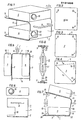
- Fig. 1 shows a frame according to the invention in a perspective view.
- Fig. 2 shows the underside of the two projectors shows a plan view of one and Fig. 4 on the other of the two plates of the frame.
- Fig. 5 shows schematically the frame according to the invention together with the projectors mounted thereon in the carrying position.
- Fig. 6 shows a front view of the frame.
- Fig. 7 illustrates the function of the inclination adjustment device. 8 shows an embodiment of such an inclination adjustment device.
- the frame 1 has a U-shaped shape and consists of two plates 2, 3 forming the two legs of the U, which are connected to one another by a transverse web 7.
- the frame 1 consists of a flexible material, for example a sheet metal, the thickness of which is selected so that it can support the weight of the two projectors 4, 5, of which the projector 4 on the plate 2 and the projector 5 on the plate 3 rests.
- the distance between the plates 2, 3 is determined by the type of projectors used and must be dimensioned such that the slide magazine can be inserted or removed in the projector 4.
- an inclination adjustment device Attached to the * free ends of the plates 2, 3 forming the legs of the U opposite the transverse web 7 is an inclination adjustment device, which will be described in more detail later and with which the inclination of the two plates 2, 3 can be changed relative to one another.
- a carrying handle 8 is fastened, which is dimensioned such that the frame can be transported with it together with the slide projectors 4, 5 fastened thereon. 5, the carrying handle is mounted exactly in the middle between the two projectors 4, 5. This ensures an optimal distribution of the weight of the two projectors, if they are of the same design, so that simple transport in the manner indicated in FIG. 5 is made possible.
- fastening devices are provided in the bottom of each projector at three locations 9, 10, 11, which may consist, for example, of threaded holes or screw nuts into which corresponding openings screws can be screwed into the plates 2, 3. Although three such fastening devices are expedient at the locations shown in FIG. 2, a plurality of fastening devices or those distributed in another way can also be provided.
- the plate 2 has fastening points 12, 13, 14 which are aligned with the fastening points 9, 10, 11 on the bottom of the slide projector 4.
- the point 15 aligned with the fastening device 9 on the projector 5 forms a center about which the projector 5 can be rotated.
- a plurality of fastening devices for example three openings, are provided on a circular arc around the center 15, through which screws can be passed.
- This rotation makes it possible to correct deviations in the horizontal coverage on the projection surface of the images projected by the two projectors. With appropriately designed connections between the projector 5 and the plate 3 of the frame 1, such a correction can be carried out by hand in a single operation.
- a cutout 18 is arranged in the crosspiece 7 in order to enable the insertion and adjustment of the projection optics 19 of the projector 4.
- the rear edges 24, 25 of the plates 2, 3 are spread apart or contracted in the arrow direction D or in the arrow direction Z by the inclination adjustment device 6.
- an element 20 of the inclination adjustment device 6 is attached to the edge 24 and an element 21 of the inclination adjustment device 6 is attached to the edge 25 such that the angle ⁇ between the element 20 and the plate 2 of the frame 1 and the angle between the element 21 and the plate 3rd of the frame 1 can change.
- the elements 20, 21, which are fixed approximately in the middle of the edges 24, 25, are pulled together or spread apart.
- a jack-like construction, scissors or a tensioner can be used as the inclination adjustment device.
- FIG. 8 A preferred embodiment of an inclination adjustment device 6, which is designed as a tensioner in the manner of a chain tensioner, is shown in detail in FIG. 8.
- Brackets 26 are fastened to the plates 2, 3, in which threaded bolts are hung, which form the elements 20, 21 of the inclination adjustment device (see FIG. 7).
- This attachment of the bolts to the plates 2, 3 allows pivoting to change the Winkelo ⁇ , ⁇ .
- a turnbuckle 27 is screwed onto the threads of the two elements 20, 21, the twist of which makes it possible for the two elements 20, 21 formed by the threaded bolts to be brought closer or closer to one another.
Landscapes
- Physics & Mathematics (AREA)
- General Physics & Mathematics (AREA)
- Projection Apparatus (AREA)
Abstract
Description
- Die Erfindung betrifft ein Gestell für eine Uberblendeinrichtung für zwei Diamagazinprojektoren, wobei die beiden Projektoren übereinander auf zwei Auflagern angeordnet sind, die in ihrer relativen Neigung zueinander durch eine Neigungsverstelleinrichtung verstellbar sind.
- Die üblichen Diamagazinprojektoren ermöglichen nur das Projezieren einzelner Dias, nicht jedoch die Überblendung zweier Dias. Um einen solchen Überblendungsprozess mit den bekannten Diamagazinprojektoren durchführen zu können, sind zwei derartiger Projektoren erforderlich, deren Lage so justiert werden muß, daß die gewünschte Überblendung erfolgt. Ohne Hilfsmittel ist dieses Justieren sehr umständlich und zeitraubend. Man hat daher bereits Vorrichtungen vorgeschlagen, mit welchen unter Verwendung von zwei Diamagazinprojektoren ein Überblendungsprozess durchgeführt werden kann.
- Bei einer bekannten Vorrichtung (US-A 3 240 118) sind zwei Projektoren nebeneinander auf einer gemeinsamen Tragplatte angeordnet. Dadurch werden die überblendeten Dias in horizontaler Richtung verzerrt. Das menschliche Auge ist jedoch an vertikale Verzerrungen besser gewöhnt als an horizontale Verzerrungen, was sich aus dem natürlichen Zusammenlauf von Gebäudekanten, Schriftzügen usw. ergibt. Da außerdem jeder moderne Projektor breiter ist als höher, bedingt die Nebeneinanderanordnung der Projektoren auch den Nachteil, daß die Optiken dieser Projektoren weiter voneinander entfernt liegen als bei einer Übereinanderanordnung, was den Verzerrungsfehler erhöht.
- Man hat daher auch bereits vorgeschlagen (US-A 4 148 453), zwei Projektoren übereinander vorzusehen. Die Projektoren sind hiebei in zwei Rahmen angeordnet, die in vertikalen Stehern allseits schwenkbar gelagert und mittels Fixierschrauben in der eingestellten Stellung arretierbar sind. Eine derartige Anordnung ermöglicht es zwar, die Bilder der beiden Projektoren auf einem gemeinsamen Bildschirm zur Deckung zu bringen, also eine Überblendung zu erreichen, jedoch ist auch bei dieser Anordnung die Justierung sehr umständlich durchzuführen. Für diese Justierung sind nämlich die Klemmschrauben, mit welchen die Rahmen an den Stehern befestigt sind, zu lösen, worauf die Rahmen händisch so verschwenkt werden müssen, daß die optische Achse jedes Projektors in die richtige Lage gebracht wird. Die Rahmen müssen dann in dieser Lage bis zum Anziehen der Klemmschrauben händisch gehalten werden.
- Ferner ist das aus den miteinander verbundenen Stehern und den Rahmen gebildete Gestell verhältnismäßig schwer und sperrig und daher nicht einfach zu transportieren.
- Die vorliegende Erfindung hat sich zur Aufgabe gestellt, ein Gestell für eine Uberblendeinrichtung für zwei Diamagazinprojektoren zu schaffen, welches einen einfachen Aufbau besitzt, leicht ist und ohne Schwierigkeiten transportiert werden kann und welches auf einfache Weise eine Justierung der beiden Diaprojektoren ermöglicht. Diese Diaprojektoren sollen hiebei zusammen mit dem Gestell transportiert werden können, ohne daß sich ihre gegenseitige Lage hiebei verändert, so daß am Ort der Vorführung eine Justierung nicht mehr erforderlich ist. Zur Lösung dieser Aufgabe schlägt die Erfindung vor, daß das Auflager für jeden der beiden Projektoren von einer Platte gebildet ist, an der der Projektor befestigt ist, wobei einer der beiden Projektoren um ein Zentrum auf der Platte drehbar und in der gewählten Lage befestigbar ist, und daß die beiden Platten durch einen sie verbindenden Quersteg zu einem im Querschnitt U-förmigen Traggestell verbunden sind, wobei die Neigungsverstelleinrichtung an den von den Platten gebildeten auslaufenden Armen des U angreift.
- Diese Neigungsverstelleinrichtung kann hiebei erfindungsgemäß eine wagenheberartige Konstruktion, eine Schere oder ein Spanner sein und ist vorzugsweise mittels Schellen, Druckstücken mit Druckzapfen od.dgl. schwenkbar mit den Platten verbunden.
- Zur Verankerung der Projektoren am Gestell kann erfindungsgemäß jeder der beiden Projektoren an seiner Platte an drei im Dreieck angeordneten Stellen, vorzugsweise mit Schrauben, befestigt sein, wobei für einen der Projektoren eine dieser Stellen das Zentrum für die Drehung des Projektors relativ zu seiner Platte bildet, wogegen für die beiden anderen Stellen in dieser Platte um das Zentrum bogenförmig verlaufende Öffnungen zum Hindurchtritt der Schrauben od.dgl. vorgesehen sind. Dadurch läßt sich auf einfache Weise einer der beiden Projektoren auf einer der Platten verdrehen und dadurch die optischen Achsen beider Projektoren in einer gemeinsamen Vertikalebene anordnen.
- Um das Gestell mit den darauf fixierten Projektoren auf einfache Weise transportieren zu können, ist gemäß einem weiteren Merkmal der Erfindung am Quersteg ein Traggriff, vorzugsweise in der Mitte zwischen den beiden Projektoren, befestigt.
- Gemäß einer bevorzugten Ausbildung der Erfindung besteht das von den Platten und dem Quersteg gebildete Traggestell einstückig aus biegsamem Material, z.B. Metallblech. Ein derartiges Gestell läßt sich auf einfache Weise herstellen, wobei durch die Biegsamkeit die Neigung der Plattenebenen relativ zueinander durch die Neigungsverstelleinrichtung verändert werden kann.
- Eine zweckmäßige Ausführungsform ergibt sich dann, wenn beide Projektoren auf den Platten so befestigt sind, daß sie in Richtung von den auslaufenden Armen des U wegprojezieren, wobei für den Lichtstrahldurchtritt des unteren Projektors eine Öffnung im Quersteg vorhanden ist.
- In der Zeichnung ist die Erfindung anhand eines Ausführungsbeispieles schematisch veranschaulicht. Fig. 1 zeigt ein erfindungsgemäßes Gestell in perspektiver Darstellung. Fig. 2 stellt die Unterseite der beiden Projektoren dar.Fig.3 zeigt eine Draufsicht auf die eine und Fig. 4 auf die andere der beiden Platten des Gestells. Fig. 5 stellt schematisch das erfindungsgemäße Gestell zusammen mit den darauf befestigten Projektoren in Tragestellung dar. Fig. 6 zeigt eine Vorderansicht des Gestells. Fig. 7 verdeutlicht die Funktion der Neigungsverstelleinrichtung. Fig. 8 zeigt eine Ausführungsform einer solchen Neigungsverstelleinrichtung.
- Das erfindungsgemäße Gestell 1 weist eine U-förmige Gestalt auf und besteht aus zwei die beiden Schenkel des U bildenden Platten 2, 3, die durch einen Quersteg 7 miteinander verbunden sind. Das Gestell 1 besteht hiebei aus einem biegsamen Material, beispielsweise aus einem Metallblech, dessen Stärke so gewählt ist, daß es das Gewicht der beiden Projektoren 4, 5 tragen kann, von welchen der Projektor 4 auf der Platte 2 und der Projektor 5 auf der Platte 3 aufruht. Der Abstand zwischen den Platten 2, 3 wird bestimmt von der Art der verwendeten Projektoren und muß so bemessen sein, daß ein Einsetzen bzw. Entnehmen des Diamagazins im Projektor 4 möglich ist.
- An den dem Quersteg 7 gegenüberliegende*reien Enden der die Schenkel des U bildenden Platten 2, 3 ist eine später noch näher beschriebene Neigungsverstelleinrichtung befestigt, mit welcher die Neigung der beiden Platten 2, 3 relativ zueinander verändert werden kann.
- Am Quersteg 7 ist ein Traggriff 8 befestigt, der so bemessen ist, daß mit ihm das Gestell zusammen mit den darauf befestigten Diaprojektoren 4, 5 transportiert werden kann. Wie auch aus Fig. 5 hervorgeht, ist der Traggriff genau in der Mitte zwischen den beiden Projektoren 4, 5 montiert. Dadurch wird eine optimale Verteilung des Gewichtes der beiden Projektoren, wenn diese gleich ausgebildet sind, gewährleistet, so daß ein einfacher Transport in der in Fig. 5 angedeuteten Weise ermöglicht wird.
- Zur Befestigung der Projektoren 4, 5 an den Platten 2, 3 sind, wie aus Fig. 2 hervorgeht, im Boden jedes Projektors an drei Stellen 9, 10, 11 Befestigungseinrichtungen vorgesehen, die beispielsweise aus Gewindelöchern oder Schraubenmuttern bestehen können, in welche entsprechende Öffnungen in den Platten 2, 3 durchsetzende Schrauben eingeschraubt werden können. Wenngleich drei solcher Befestigungseinrichtungen an den in Fig. 2 dargestellten Stellen zweckmäßig sind, so können auch mehrere oder auf andere Weise verteilte Befestigungseinrichtigungen vorgesehen werden.
- Wie aus Fig. 3 hervorgeht, weist die Platte 2 Befestigungsstellen 12, 13, 14 auf, die mit den Befestigungsstellen 9, 10, 11 am Boden des Diaprojektors 4 fluchten.
- Fig. 4 zeigt die Befestigungseinrichtungen auf der Platte 3. Die mit der Befestigungseinrichtung 9 am Projektor 5 fluchtende Stelle 15 bildet ein Zentrum, um welches der Projektor 5 drehbar ist. An den mit den Befestigungseinrichtungen 10, 11 des Projektors 5 fluchtenden Stellen 16, 17 sind mehrere auf einem Kreisbogen um das Zentrum 15 angeordnete Befestigungseinrichtungen, beispielsweise drei Öffnungen vorgesehen, durch welche Schrauben hindurchgeführt werden können. Dadurch wird eine Verschiebung und Fixierung des Projektors 5 in der Ebene der Platte 3 um das Zentrum 15 ermöglicht, wie dies durch die Radien r16 und r17 angedeutet ist. Durch diese Drehung wird ermöglicht, Abweichungen in der horizontalen Deckung auf der Projektionsfläche der von den beiden Projektoren projezierten Bilder zu korrigieren. Bei entsprechend ausgebildeten Verbindungen zwischen dem Projektor 5 und der Platte 3 des Gestells 1 läßt sich eine solche Korrektur mit der Hand in einem einzigen Arbeitsvorgang durchführen.
- Wie aus Fig. 6 hervorgeht, ist im Quersteg 7 ein Ausschnitt 18 angeordnet, um das Einsetzen und Justieren der Projektionsoptik 19 des Projektors 4 zu ermöglichen.
- Fig. 7 zeigt die Funktion der Neigungsverstelleinrichtung 6. Um die Neigung der Platte 2 relativ zur Platte 3 zu verändern, werden die hinteren Ränder 24, 25 der Platten 2, 3 durch die Neigungsverstelleinrichtung 6 in Pfeilrichtung D auseinandergesprei_zt oder in Pfeilrichtung Z zusammengezogen. Hiezu wird am Rand 24 ein Element 20 der Neigungsverstelleinrichtung 6 und am Rand 25 ein Element 21 der Neigungsverstelleinrichtung 6 derart befestigt, daß sich der Winkel α zwischen dem Element 20 und der Platte 2 des Gestells 1 und der Winkele zwischen dem Element 21 und der Platte 3 des Gestells 1 ändern können. Die Elemente 20, 21, welche etwa in der Mitte der Ränder 24, 25 festgelegt sind, werden hiebei zusammengezogen oder gespreizt.
- Als Neigungsverstelleinrichtung kann beispielsweise eine wagenheberartige Konstruktion, eine Schere oder ein Spanner verwendet werden.
- Eine bevorzugte Ausführung einer Neigungsverstelleinrichtung 6, welche als Spanner nach Art eines Kettenspanners ausgebildet ist, in in Fig. 8 im Detail dargestellt. An den Platten 2, 3 sind Bügel 26 befestigt, in die mit einem Gewinde versehene Bolzen eingehängt sind, welche die Elemente 20, 21 der Neigungsverstelleinrichtung (siehe Fig.7) bilden. Diese Befestigung der Bolzen an den Platten 2, 3 ermöglicht eine Verschwenkung zwecks Änderung der Winkelo α, β. Auf die Gewinde der beiden Elemente 20, 21 ist ein Spannschloß 27 aufgeschraubt, durch-dessen Verdrehung die beiden von den Gewindebolzen gebildeten Elemente 20, 21 einander genähert oder voneinander entfernt werden können.
Claims (7)
Applications Claiming Priority (2)
| Application Number | Priority Date | Filing Date | Title |
|---|---|---|---|
| AT305682A AT377103B (de) | 1982-08-10 | 1982-08-10 | Gestell fuer eine ueberblendeinrichtung fuer zwei diamagazinprojektoren |
| AT3056/82 | 1982-08-10 |
Publications (3)
| Publication Number | Publication Date |
|---|---|
| EP0101430A2 true EP0101430A2 (de) | 1984-02-22 |
| EP0101430A3 EP0101430A3 (en) | 1986-06-11 |
| EP0101430B1 EP0101430B1 (de) | 1989-04-19 |
Family
ID=3544612
Family Applications (1)
| Application Number | Title | Priority Date | Filing Date |
|---|---|---|---|
| EP19830890128 Expired EP0101430B1 (de) | 1982-08-10 | 1983-08-10 | Gestell für eine Überblendeinrichtung für zwei Diamagazinprojektoren |
Country Status (3)
| Country | Link |
|---|---|
| EP (1) | EP0101430B1 (de) |
| AT (1) | AT377103B (de) |
| DE (1) | DE3379682D1 (de) |
Cited By (3)
| Publication number | Priority date | Publication date | Assignee | Title |
|---|---|---|---|---|
| FR2561792A1 (fr) * | 1984-03-20 | 1985-09-27 | Mollaret Patrice | Box audiovisuel |
| DE4124502A1 (de) * | 1991-07-24 | 1993-01-28 | Guido Dipl Ing Haehnel | Diaprojektions-bildwandler |
| DE19509334A1 (de) * | 1995-03-15 | 1996-09-19 | Otto Ing Gutweniger | Stereo-Projektor und Stereo-Betrachter |
Family Cites Families (9)
| Publication number | Priority date | Publication date | Assignee | Title |
|---|---|---|---|---|
| AT204304B (de) * | 1956-09-29 | 1959-07-10 | Bauer Eugen Gmbh | Schutzhaube für tragbare Bildwerfer |
| US3059529A (en) * | 1957-05-21 | 1962-10-23 | James W Lucas | Portable projection adapter |
| US3093030A (en) * | 1959-02-09 | 1963-06-11 | Carrillo Nestor | Slide projector with dissolve |
| US3240118A (en) * | 1962-11-21 | 1966-03-15 | Mrs Louis Bose | Dual slide projector apparatus for producing transition effects |
| DE1911775A1 (de) * | 1969-03-07 | 1970-10-29 | Heye Friedrich W | Optisches Geraet zur Zusammenfassung mehrerer getrennt einstellbarer Projektionsbilder zu einem Kombinationsbild |
| DE2246746A1 (de) * | 1972-09-22 | 1974-04-04 | Braun Ag | Projektionseinheit, insbesondere zur projektion von diapositiven |
| US3912385A (en) * | 1973-07-02 | 1975-10-14 | Columbia Scient Ind | Multi-media projector stand |
| US4036459A (en) * | 1976-02-27 | 1977-07-19 | Optical Associates, Inc. | Instrument swivel bracket |
| FR2473737A1 (fr) * | 1979-12-04 | 1981-07-17 | Rech Geolog Miniere | Dispositif pour la projection d'images a partir d'au moins deux appareils |
-
1982
- 1982-08-10 AT AT305682A patent/AT377103B/de not_active IP Right Cessation
-
1983
- 1983-08-10 DE DE8383890128T patent/DE3379682D1/de not_active Expired
- 1983-08-10 EP EP19830890128 patent/EP0101430B1/de not_active Expired
Cited By (3)
| Publication number | Priority date | Publication date | Assignee | Title |
|---|---|---|---|---|
| FR2561792A1 (fr) * | 1984-03-20 | 1985-09-27 | Mollaret Patrice | Box audiovisuel |
| DE4124502A1 (de) * | 1991-07-24 | 1993-01-28 | Guido Dipl Ing Haehnel | Diaprojektions-bildwandler |
| DE19509334A1 (de) * | 1995-03-15 | 1996-09-19 | Otto Ing Gutweniger | Stereo-Projektor und Stereo-Betrachter |
Also Published As
| Publication number | Publication date |
|---|---|
| EP0101430A3 (en) | 1986-06-11 |
| ATA305682A (de) | 1984-06-15 |
| AT377103B (de) | 1985-02-11 |
| DE3379682D1 (en) | 1989-05-24 |
| EP0101430B1 (de) | 1989-04-19 |
Similar Documents
| Publication | Publication Date | Title |
|---|---|---|
| DE19601380A1 (de) | Zielscheibenanordnung | |
| DE3340564C2 (de) | ||
| DE8805679U1 (de) | Tisch mit höhenverstellbarer und kippbarer Tischplatte | |
| EP0101430B1 (de) | Gestell für eine Überblendeinrichtung für zwei Diamagazinprojektoren | |
| DE3216500A1 (de) | Reparaturstand fuer kraftfahrzeugaufbauten | |
| DE2030546C3 (de) | Schutzhelm mit hochklappbarer Schutzbrille | |
| DE2637298A1 (de) | Wetterschutzvorrichtung fuer ein zerlegbares geruest | |
| DE2834319A1 (de) | Richtgeraet | |
| DE2165877A1 (de) | Vorrichtung und verfahren zur befestigung von bindungen auf skiern | |
| EP0545039B1 (de) | Werbevorrichtung | |
| DE3207228C2 (de) | ||
| DE1291098B (de) | Vorrichtung zum Aufbringen von Umleimern aus Furnier oder Kunststoff | |
| EP0316661A1 (de) | Vorrichtung zur Schaustellung von insbesondere Fliesen | |
| DE3002665C2 (de) | Laserstrahlmessermanipulator | |
| DE3207966A1 (de) | Vorrichtung zum loesbaren verbinden rohr- oder stangenfoermiger gestellelemente | |
| DE939742C (de) | Vorrichtung zur Verbolzung der Ausbaurahmen beim Streckenausbau | |
| DE263317C (de) | ||
| DE514627C (de) | Anschiebbare Vorrichtung zum Neigen des Objektivtraegers bei Photokameras | |
| DE534054C (de) | Haltevorrichtung fuer zu loetende Dachrinnen | |
| DE963477C (de) | Nach dem Verfahren der Doppelprojektion arbeitendes photogrammetrisches Auswertegeraet mit mehreren Projektionskammern | |
| DE593462C (de) | Lehrenzwinge fuer Gattersaegen | |
| DE1249558B (de) | ||
| DE2215769A1 (de) | Lichtbildprojektionswand | |
| DE566800C (de) | Vorschild fuer einen Kohlenkasten | |
| DE553198C (de) | Spannrahmen fuer Felle |
Legal Events
| Date | Code | Title | Description |
|---|---|---|---|
| PUAI | Public reference made under article 153(3) epc to a published international application that has entered the european phase |
Free format text: ORIGINAL CODE: 0009012 |
|
| AK | Designated contracting states |
Designated state(s): BE CH DE FR GB IT LI NL SE |
|
| PUAL | Search report despatched |
Free format text: ORIGINAL CODE: 0009013 |
|
| AK | Designated contracting states |
Kind code of ref document: A3 Designated state(s): BE CH DE FR GB IT LI NL SE |
|
| 17P | Request for examination filed |
Effective date: 19861128 |
|
| 17Q | First examination report despatched |
Effective date: 19880531 |
|
| GRAA | (expected) grant |
Free format text: ORIGINAL CODE: 0009210 |
|
| AK | Designated contracting states |
Kind code of ref document: B1 Designated state(s): BE CH DE FR GB IT LI NL SE |
|
| PG25 | Lapsed in a contracting state [announced via postgrant information from national office to epo] |
Ref country code: SE Effective date: 19890419 Ref country code: NL Effective date: 19890419 Ref country code: IT Free format text: LAPSE BECAUSE OF FAILURE TO SUBMIT A TRANSLATION OF THE DESCRIPTION OR TO PAY THE FEE WITHIN THE PRESCRIBED TIME-LIMIT;WARNING: LAPSES OF ITALIAN PATENTS WITH EFFECTIVE DATE BEFORE 2007 MAY HAVE OCCURRED AT ANY TIME BEFORE 2007. THE CORRECT EFFECTIVE DATE MAY BE DIFFERENT FROM THE ONE RECORDED. Effective date: 19890419 Ref country code: BE Effective date: 19890419 |
|
| REF | Corresponds to: |
Ref document number: 3379682 Country of ref document: DE Date of ref document: 19890524 |
|
| GBT | Gb: translation of ep patent filed (gb section 77(6)(a)/1977) | ||
| ET | Fr: translation filed | ||
| PG25 | Lapsed in a contracting state [announced via postgrant information from national office to epo] |
Ref country code: LI Effective date: 19890831 Ref country code: CH Effective date: 19890831 |
|
| NLV1 | Nl: lapsed or annulled due to failure to fulfill the requirements of art. 29p and 29m of the patents act | ||
| PLBE | No opposition filed within time limit |
Free format text: ORIGINAL CODE: 0009261 |
|
| STAA | Information on the status of an ep patent application or granted ep patent |
Free format text: STATUS: NO OPPOSITION FILED WITHIN TIME LIMIT |
|
| 26N | No opposition filed | ||
| REG | Reference to a national code |
Ref country code: CH Ref legal event code: PL |
|
| PGFP | Annual fee paid to national office [announced via postgrant information from national office to epo] |
Ref country code: GB Payment date: 19910730 Year of fee payment: 9 |
|
| PGFP | Annual fee paid to national office [announced via postgrant information from national office to epo] |
Ref country code: DE Payment date: 19911030 Year of fee payment: 9 |
|
| PGFP | Annual fee paid to national office [announced via postgrant information from national office to epo] |
Ref country code: FR Payment date: 19911126 Year of fee payment: 9 |
|
| PG25 | Lapsed in a contracting state [announced via postgrant information from national office to epo] |
Ref country code: GB Effective date: 19920810 |
|
| GBPC | Gb: european patent ceased through non-payment of renewal fee |
Effective date: 19920810 |
|
| PG25 | Lapsed in a contracting state [announced via postgrant information from national office to epo] |
Ref country code: FR Effective date: 19930430 |
|
| PG25 | Lapsed in a contracting state [announced via postgrant information from national office to epo] |
Ref country code: DE Effective date: 19930501 |
|
| REG | Reference to a national code |
Ref country code: FR Ref legal event code: ST |