EP0096808B1 - Streufeldarme Funk-Entstördrossel - Google Patents
Streufeldarme Funk-Entstördrossel Download PDFInfo
- Publication number
- EP0096808B1 EP0096808B1 EP83105463A EP83105463A EP0096808B1 EP 0096808 B1 EP0096808 B1 EP 0096808B1 EP 83105463 A EP83105463 A EP 83105463A EP 83105463 A EP83105463 A EP 83105463A EP 0096808 B1 EP0096808 B1 EP 0096808B1
- Authority
- EP
- European Patent Office
- Prior art keywords
- windings
- interference suppression
- core
- radio interference
- choke
- Prior art date
- Legal status (The legal status is an assumption and is not a legal conclusion. Google has not performed a legal analysis and makes no representation as to the accuracy of the status listed.)
- Expired
Links
- 238000004804 winding Methods 0.000 claims abstract description 59
- 230000001629 suppression Effects 0.000 claims abstract description 10
- 239000000696 magnetic material Substances 0.000 claims description 2
- 230000006978 adaptation Effects 0.000 claims 1
- 230000007704 transition Effects 0.000 abstract 2
- 239000007779 soft material Substances 0.000 abstract 1
- 238000009413 insulation Methods 0.000 description 2
- 238000004519 manufacturing process Methods 0.000 description 2
- 229910000859 α-Fe Inorganic materials 0.000 description 2
- 230000000694 effects Effects 0.000 description 1
- 239000011810 insulating material Substances 0.000 description 1
- 238000002955 isolation Methods 0.000 description 1
- 238000000034 method Methods 0.000 description 1
- 238000004904 shortening Methods 0.000 description 1
- 238000005476 soldering Methods 0.000 description 1
Images
Classifications
-
- H—ELECTRICITY
- H01—ELECTRIC ELEMENTS
- H01F—MAGNETS; INDUCTANCES; TRANSFORMERS; SELECTION OF MATERIALS FOR THEIR MAGNETIC PROPERTIES
- H01F17/00—Fixed inductances of the signal type
- H01F17/04—Fixed inductances of the signal type with magnetic core
- H01F17/06—Fixed inductances of the signal type with magnetic core with core substantially closed in itself, e.g. toroid
- H01F17/062—Toroidal core with turns of coil around it
-
- H—ELECTRICITY
- H01—ELECTRIC ELEMENTS
- H01F—MAGNETS; INDUCTANCES; TRANSFORMERS; SELECTION OF MATERIALS FOR THEIR MAGNETIC PROPERTIES
- H01F27/00—Details of transformers or inductances, in general
- H01F27/02—Casings
- H01F27/027—Casings specially adapted for combination of signal type inductors or transformers with electronic circuits, e.g. mounting on printed circuit boards
Definitions
- the invention relates to a low-stray radio interference suppression choke, in particular a current-compensated ring core multiple choke, consisting of a plurality of windings applied to an electrically insulated ring core made of soft magnetic material, in particular ferrite, each of which is separated into partial windings connected in series, preferably with the same number of turns, which are wound onto sections of the toroidal core, which are preferably diametrical to one another.
- a low-stray radio interference suppression choke in particular a current-compensated ring core multiple choke, consisting of a plurality of windings applied to an electrically insulated ring core made of soft magnetic material, in particular ferrite, each of which is separated into partial windings connected in series, preferably with the same number of turns, which are wound onto sections of the toroidal core, which are preferably diametrical to one another.
- the present invention has for its object to provide a stray field radio interference suppression choke of the type mentioned, in particular a current-compensated toroidal multiple choke, which is characterized by internal series connection of the partial windings and electrical isolation, which avoids the manufacturing disadvantages mentioned.
- the invention provides for a radio interference suppression choke of the type mentioned that each winding consists of a continuous, uninterrupted wire divided into the partial windings and that the windings are each separated by an insulating cap, which on the toroid, and if necessary, on the winding previously wound, viewed in the winding sequence.
- CH-A-539 328 does contain an illustration of a choke of the type mentioned in the introduction, in which the windings, each consisting of two partial windings, are also made from a continuously wound wire. This is a representation of the winding scheme. This document does not contain any specific information on how to actually wind the partial windings uninterruptedly.
- This type of winding eliminates the need for complex contacting of the partial winding ends or beginnings. After completion of a partial winding, the wire end only has to be guided to the diametrically opposite ring core section and finally the second partial winding has to be applied to the ring core.
- the insulating cap does not only effect the otherwise complex insulation of the overlapping windings; with appropriate training, it also ensures that the partial windings are properly fixed.
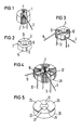
- FIGS. 1 to 3 shows the winding structure for a stray field-poor, current-compensated toroidal double choke.
- a first partial winding 2 and diametrically thereto a second partial winding 4 is wound on an electrically insulated ferrite toroidal core 1, the end of the partial winding 2 being continuous, i. H. is transferred into the beginning of the partial winding 4 without interruption.
- the beginning 3 and end 5 of the overall winding 2, 4 are brought out on the same side in the exemplary embodiment shown, which is not absolutely necessary.
- the beginning and end of the winding can also be guided radially to the opposite side.
- This insulating cap in its sections 14, 15 pushed onto the partial windings 2, 4, has an enlarged cross section and is equipped with an opening 9 which is open at the edge and serves, as shown in FIG. 3, to lead out the winding start 3.
- the insulating cap 6 In its sections 7, 8 offset from sections 14, 15 by 90 degrees, the insulating cap 6 has a reduced cross section. This ensures the fixing of the partial windings 10, 12 wound on the insulating cap 6 together with the ring core 1 according to FIG. 3, whose winding start 11 or winding end 13 can also be pulled radially to the opposite side, in contrast to the illustration according to FIG. 3 .
- the insulating cap 20 shown in FIG. 5 is pushed directly onto the ring core, ie without previously winding up partial windings.
- the insulating cap 20 has parallel, congruent and diametrically spaced segments 25, 26 at a distance from the cup bottom, which are open radially outwards and in the cup bottom circumferential direction and thus pocket-shaped slots or insulating channels 23, 24 for the Form a bridge between the partial windings 2, 4 or for the return of the winding end 5.
- segments 25, 26, sections 7, 8 according to FIG. 2 are provided with sections 21, 22 which have a tapered cross section and which likewise ensure that the partial windings 2, 4 are fixed.
Landscapes
- Engineering & Computer Science (AREA)
- Power Engineering (AREA)
- Microelectronics & Electronic Packaging (AREA)
- Coils Or Transformers For Communication (AREA)
- Pharmaceuticals Containing Other Organic And Inorganic Compounds (AREA)
- Control Of Motors That Do Not Use Commutators (AREA)
- Input Circuits Of Receivers And Coupling Of Receivers And Audio Equipment (AREA)
- Coils Of Transformers For General Uses (AREA)
Description
- Die Erfindung betrifft eine streufeldarme Funk-Entstördrossel, insbesondere stromkompensierte Ringkern-Mehrfachdrossel, bestehend aus mehreren, auf einen elektrisch isolierten Ringkern aus weichmagnetischem Werkstoff, insbesondere Ferrit, aufgebrachten Wicklungen, die jeweils in in Reihe zueinander geschaltete Teilwicklungen, vorzugsweise gleicher Windungszahl, aufgetrennt sind, die auf vorzugsweise zueinander diametrale, Abschnitte des Ringkerns aufgewickelt sind.
- Bei den bereits bekannten Ringkern-Mehrfachdrosseln dieser Art erfolgt die Reihenschaltung der Teilwicklungen durch einen getrennten, den Wickel-Arbeitsgängen nachgeschalteten Arbeitsgang. Bei Ringkern-Zweifachdrosseln erfordert dies z. B. zwei Verdrallvorgänge, d. h. zwei Vorgänge, bei denen jeweils die zu verbindenden Enden bzw. Anfänge der Teilwicklungen miteinander verdrallt werden, das Tauchlöten der verdrallten Wickeldrähte, ihr Kürzen und schließlich ihre Isolierung, die üblich mittels bandförmigem Isoliermaterial durchgeführt wird. Dieser Fertigungsaufwand erhöht sich entsprechend bei Ringkerndrosseln mit entsprechend höherer Gesamtwicklungs- und damit höherer Teilwicklungszahl.
- Der vorliegenden Erfindung liegt die Aufgabe zugrunde, eine streufeldarme Funk-Entstördrossel der eingangs genannten Art, insbesondere eine stromkompensierte Ringkern-Mehrfachdrossel, die sich durch interne Reihenschaltung der Teilwicklungen und Potentialtrennung auszeichnet, zu schaffen, welche die genannten fertigungstechnischen Nachteile vermeidet.
- Zur Lösung dieser Aufgabe sieht die Erfindung bei einer Funk-Entstördrossel der eingangs genannten Art vor, daß jede Wicklung aus einem fortlaufenden, unterbrechungsfrei in die Teilwicklungen aufgeteilten Draht besteht und daß die Wicklungen jeweils durch eine Isolierkappev voneinander getrennt sind, die auf den Ringkern, und ggf. auf die - betrachtet in Wickelreihenfolge - vorhergehend aufgewickelte Wicklung, aufgeschoben ist.
- Die CH-A-539 328 enthält zwar eine Darstellung einer Drossel der eingangs genannten Art, in der die jeweils aus zwei Teilwicklungen bestehende Wicklungen ebenfalls aus einem fortlaufend gewickelten Draht dargestellt wird. Dabei handelt es sich um eine Darstellung des Wicklungsschemas. Einen konkreten Hinweis, die Teilwicklungen tatsächlich unterbrechungsfrei zu wickeln, enthält diese Druckschrift nicht.
- Durch diese Wickelart erübrigt sich das erwähnte, aufwendige Kontaktieren der Teilwickelenden bzw. -anfänge. Nach Fertigstellung einer Teilwicklung muß das Drahtende lediglich zum diametral gegenüberliegenden Ringkernabschnitt geführt und endlich die zweite Teilwicklung auf den Ringkern aufgebracht werden. Die Isolierkappe bewirkt nicht bloß die ansonsten nur aufwendig realisierbare Isolierung der sich einander überlappenden Wicklungen ; bei entsprechender Ausbildung gewährleistet sie auch eine einwandfreie Fixierung der Teilwicklungen.
- Die Erfindung wird nachstehend anhand von Ausführungsbeispielen näher erläutert. Es zeigt :
- Fig. 1 bis 3 ein erstes Ausführungsbeispiel einer Ringkern-Zweifachdrossei in perspektivischer und teilweise auseinandergezogener Darstellung,
- Fig. 4 ein zweites Ausführungsbeispiel einer Ringkern-Zweifachdrossel in perspektivischer Darstellung,
- Fig. 5 eine perspektivische Ansicht der Isolierkappe nach Fig. 4.
- Am Beispiel nach Fig. 1 bis 3 ist der Wickelaufbau für eine streufeldarme, stromkompensierte Ringkern-Zweifachdrossel erkennbar. Gemäß Fig. 1 ist auf einen elektrisch isolierten Ferrit-Ringkern 1 eine erste Teilwicklung 2 und diametral hierzu eine zweite Teilwicklung 4 aufgewickelt, wobei das Ende der Teilwicklung 2 fortlaufend, d. h. unterbrechungsfrei in den Anfang der Teilwicklung 4 übergeführt ist. Anfang 3 und Ende 5 der Gesamtwicklung 2, 4 sind im gezeigten Ausführungsbeispiel auf der gleichen Seite herausgeführt, was nicht unbedingt erforderlich ist. Wickelanfang und -endekönnen auch radial zur gegenüberliegenden Seite geführt sein.
- Auf den gemäß Fig. 1 gewickelten Ringkern 1 ist eine Isolierkappe 6, die als kreisringförmiger Becher ausgebildet ist, aufgeschoben. Diese Isolierkappe weist in ihren auf die Teilwicklungen 2, 4 aufgeschobenen Abschnitten 14, 15 vergrößerten Querschnitt auf und ist mit einem randoffenen Durchbruch 9 ausgerüstet, der - wie in Fig. 3 dargestellt - zur Herausführung des Wickelanfanges 3 dient.
- In ihren zu den Abschnitten 14, 15 um 90 Grad versetzten Abschnitten 7, 8 besitzt die Isolierkappe 6 verkleinerten Querschnitt. Hierdurch wird die Fixierung der gemäß Fig. 3 auf die Isolierkappe 6 samt Ringkern 1 aufgewickelten Teilwicklungen 10, 12 gewährleistet, deren Wickelanfang 11 bzw. Wickelende 13 gleichfalls, und zwar im Unterschied zur Darstellung nach Fig. 3, radial zur gegenüberliegenden Seite gezogen werden können.
- Im Ausführungsbeispiel nach Fig. 4, 5 sind gleiche Teile, d. h. insbesondere die Wicklungen und ihre Wickelenden bzw. -anfänge mit gleichen Bezugszeichen bezeichnet. Die in Fig. 5 dargestellte Isolierkappe 20 ist unmittelbar, d. h. ohne vorheriges Aufwickeln von Teilwicklungen auf den Ringkern, auf diesen aufgeschoben. Die Isolierkappe 20 besitzt parallel, deckungsgleich und im Abstand zum Becherboden diametral zueinander ausgerichtete Segmente 25, 26, die radial nach außen sowie in Becherbodenumlaufrichtung offen sind und so taschenförmige Schlitze bzw. Isolierkanäle 23, 24 für die Brücke zwischen den Teilwicklungen 2, 4 bzw. für die Rückführung des Wickelendes 5 bilden. Durch die Ausrüstung der Isolierkappe 20 mit Segmenten 25, 26 werden den Abschnitten 7, 8 gemäß Fig. 2 vergleichbare Abschnitte 21, 22 verjüngten Querschnitts geschaffen, die gleichfalls die Fixierung der Teilwicklungen 2, 4 gewährleisten.
Claims (5)
Priority Applications (1)
| Application Number | Priority Date | Filing Date | Title |
|---|---|---|---|
| AT83105463T ATE18824T1 (de) | 1982-06-02 | 1983-06-01 | Streufeldarme funk-entstoerdrossel. |
Applications Claiming Priority (2)
| Application Number | Priority Date | Filing Date | Title |
|---|---|---|---|
| DE3220737 | 1982-06-02 | ||
| DE19823220737 DE3220737A1 (de) | 1982-06-02 | 1982-06-02 | Streufeldarme funk-entstoerdrossel |
Publications (2)
| Publication Number | Publication Date |
|---|---|
| EP0096808A1 EP0096808A1 (de) | 1983-12-28 |
| EP0096808B1 true EP0096808B1 (de) | 1986-03-26 |
Family
ID=6165082
Family Applications (1)
| Application Number | Title | Priority Date | Filing Date |
|---|---|---|---|
| EP83105463A Expired EP0096808B1 (de) | 1982-06-02 | 1983-06-01 | Streufeldarme Funk-Entstördrossel |
Country Status (5)
| Country | Link |
|---|---|
| US (1) | US4578664A (de) |
| EP (1) | EP0096808B1 (de) |
| AT (1) | ATE18824T1 (de) |
| DE (2) | DE3220737A1 (de) |
| FI (1) | FI78189C (de) |
Families Citing this family (20)
| Publication number | Priority date | Publication date | Assignee | Title |
|---|---|---|---|---|
| GB8613314D0 (en) * | 1986-06-02 | 1986-07-09 | Era Patents Ltd | Microwave apparatus |
| DE3811983A1 (de) * | 1988-04-11 | 1989-10-19 | Siemens Ag | Anordnung zum betrieb einer symmetrischen hochfrequenz-antenne |
| DE3840523A1 (de) * | 1988-12-01 | 1990-06-07 | Vogt Electronic Ag | Mehrpolige entstoerdrossel fuer datenleitungen |
| GB8928899D0 (en) * | 1989-12-21 | 1990-02-28 | Knowles Electronics Co | Coil assemblies |
| FR2687831B1 (fr) * | 1992-02-24 | 1994-04-08 | Merlin Gerin | Transformateur en forme de tore pour capteur differentiel fonctionnant en classe a. |
| JP3317045B2 (ja) * | 1994-10-14 | 2002-08-19 | 株式会社村田製作所 | コモンモードチョークコイル |
| GB2336473A (en) * | 1998-04-15 | 1999-10-20 | Motorola Gmbh | An inductor |
| DE19848827A1 (de) | 1998-10-22 | 2000-05-04 | Vacuumschmelze Gmbh | Vorrichtung zur Dämpfung von Störspannungen |
| US6507260B1 (en) * | 2000-04-27 | 2003-01-14 | Echelon Corporation | Electrical transformer for use with twisted pair |
| US7023313B2 (en) * | 2003-07-16 | 2006-04-04 | Marvell World Trade Ltd. | Power inductor with reduced DC current saturation |
| US7489219B2 (en) * | 2003-07-16 | 2009-02-10 | Marvell World Trade Ltd. | Power inductor with reduced DC current saturation |
| US7307502B2 (en) * | 2003-07-16 | 2007-12-11 | Marvell World Trade Ltd. | Power inductor with reduced DC current saturation |
| US7760525B2 (en) * | 2003-08-21 | 2010-07-20 | Marvell World Trade Ltd. | Voltage regulator |
| US7872454B2 (en) * | 2003-08-21 | 2011-01-18 | Marvell World Trade Ltd. | Digital low dropout regulator |
| US8324872B2 (en) * | 2004-03-26 | 2012-12-04 | Marvell World Trade, Ltd. | Voltage regulator with coupled inductors having high coefficient of coupling |
| US7190152B2 (en) * | 2004-07-13 | 2007-03-13 | Marvell World Trade Ltd. | Closed-loop digital control system for a DC/DC converter |
| DE102006043371B4 (de) * | 2006-09-15 | 2010-12-23 | Tq-Systems Gmbh | Elektrische Bauelemente mit verbesserter elektromagnetischer Verträglichkeit (EMV), insbesondere reduzierter elektromagnetischer Interferenzen (EMI) |
| US9872109B2 (en) | 2014-12-17 | 2018-01-16 | Knowles Electronics, Llc | Shared coil receiver |
| TW201624507A (zh) * | 2014-12-23 | 2016-07-01 | 台達電子工業股份有限公司 | 適用疊層繞法之磁性元件 |
| US20230197336A1 (en) * | 2021-12-21 | 2023-06-22 | Our Next Energy, Inc. | Single core cross-coupled multi-phase inductor |
Family Cites Families (11)
| Publication number | Priority date | Publication date | Assignee | Title |
|---|---|---|---|---|
| CA642616A (en) * | 1962-06-12 | The English Electric Company Limited | Electrical inductors | |
| US1897604A (en) * | 1930-09-23 | 1933-02-14 | Western Electric Co | Electromagnetic device |
| US2216863A (en) * | 1934-08-31 | 1940-10-08 | Hartford Nat Bank & Trust Co | Molding |
| US3068381A (en) * | 1956-05-17 | 1962-12-11 | Cie Ind Des Telephones | Manufacture of toroidal coils |
| US3032729A (en) * | 1957-05-16 | 1962-05-01 | Phillips Petroleum Co | Temperature stable transformer |
| US3027526A (en) * | 1957-12-23 | 1962-03-27 | Burroughs Corp | Magnetic core assembly |
| FR1350868A (fr) * | 1962-12-21 | 1964-01-31 | Materiel Electrique S W Le | Tore isolé sur lequel sont bobinés au moins deux enroulements |
| GB1105294A (en) * | 1965-07-02 | 1968-03-06 | Lucas Industries Ltd | Transformers |
| DE2050312A1 (de) * | 1970-10-13 | 1972-04-20 | Siemens Ag | Mehrfachdrossel mit Dämpfung von symmetrischen Störströmen |
| DE2228651C2 (de) * | 1972-06-13 | 1974-07-11 | Licentia Patent-Verwaltungs-Gmbh, 6000 Frankfurt | Ringkernspule |
| DE2825152C2 (de) * | 1978-06-08 | 1980-08-28 | Standard Elektrik Lorenz Ag, 7000 Stuttgart | Ringkernübertrager oder Ringkernspule mit Halterung |
-
1982
- 1982-06-02 DE DE19823220737 patent/DE3220737A1/de not_active Withdrawn
-
1983
- 1983-06-01 EP EP83105463A patent/EP0096808B1/de not_active Expired
- 1983-06-01 FI FI831974A patent/FI78189C/fi not_active IP Right Cessation
- 1983-06-01 DE DE8383105463T patent/DE3362672D1/de not_active Expired
- 1983-06-01 AT AT83105463T patent/ATE18824T1/de not_active IP Right Cessation
-
1985
- 1985-07-29 US US06/761,295 patent/US4578664A/en not_active Expired - Fee Related
Also Published As
| Publication number | Publication date |
|---|---|
| FI831974L (fi) | 1983-12-03 |
| FI831974A0 (fi) | 1983-06-01 |
| FI78189B (fi) | 1989-02-28 |
| DE3220737A1 (de) | 1983-12-08 |
| DE3362672D1 (en) | 1986-04-30 |
| EP0096808A1 (de) | 1983-12-28 |
| US4578664A (en) | 1986-03-25 |
| FI78189C (fi) | 1989-06-12 |
| ATE18824T1 (de) | 1986-04-15 |
Similar Documents
| Publication | Publication Date | Title |
|---|---|---|
| EP0096808A1 (de) | Streufeldarme Funk-Entstördrossel | |
| DE69105673T2 (de) | Transformator. | |
| DE4344459C2 (de) | Spulenanordnung | |
| DE10020949A1 (de) | Kontaktloser Transformator sowie eine mit diesem Transformator ausgestattete Fahrzeug-Signalrelaisanordnung | |
| DE4333253A1 (de) | Schaltungsanordnung zur Anpassung eines erdunsymmetrischen Leitungssystems an ein erdsymmetrisches Leitungssystem | |
| DE3330881A1 (de) | Halterung fuer eine insbesondere stromkompensierte ferrit-ringkerndrossel | |
| WO1981001219A1 (fr) | Bobinage electrique pour un transformateur une self ou analogue | |
| DE1297217B (de) | Roehrenwicklung fuer Transformatoren | |
| DE4326583A1 (de) | Hochfrequenz-Leistungstransformator | |
| DD290738A5 (de) | Sende- und/oder empfangsspule aus mehrebenenleiterplatte | |
| DE2230587B2 (de) | Induktives Bauelement | |
| DE3222027A1 (de) | Elektrischer uebertrager | |
| DE4239818C2 (de) | Bewickelter Ringkern | |
| DE2637604B2 (de) | Verteilte Verzögerungsleitung | |
| DE2503691A1 (de) | Ringkernwandler | |
| DE69128478T2 (de) | Spulen mit bandwindungen | |
| DE3022070C2 (de) | Schirmkörper für bewickelte Kernschenkel von Transformatoren, Drosselspulen u.dgl. | |
| DE102016219788B4 (de) | Verfahren zur Herstellung eines Leiterplattenstromwandlers | |
| DE2418230A1 (de) | Kapazitiv gesteuerte hochspannungswicklung aus scheibenspulen | |
| DE2229859B2 (de) | Elektrische spule | |
| DE2651734A1 (de) | Spulenkoerper | |
| DE954804C (de) | Kurzwellentransformator | |
| DE3107059A1 (de) | Elektrischer uebertrager | |
| DE2556372A1 (de) | Kapazitiv gesteuerte lagenwicklung | |
| DE2148475C3 (de) | Hochfrequenzspule mit einer Drahtwicklung und einem gedruckten Wicklungsteil mit einer Anzapfung |
Legal Events
| Date | Code | Title | Description |
|---|---|---|---|
| PUAI | Public reference made under article 153(3) epc to a published international application that has entered the european phase |
Free format text: ORIGINAL CODE: 0009012 |
|
| AK | Designated contracting states |
Designated state(s): AT CH DE FR GB IT LI NL SE |
|
| 17P | Request for examination filed |
Effective date: 19840626 |
|
| GRAA | (expected) grant |
Free format text: ORIGINAL CODE: 0009210 |
|
| ITF | It: translation for a ep patent filed | ||
| AK | Designated contracting states |
Kind code of ref document: B1 Designated state(s): AT CH DE FR GB IT LI NL SE |
|
| REF | Corresponds to: |
Ref document number: 18824 Country of ref document: AT Date of ref document: 19860415 Kind code of ref document: T |
|
| REF | Corresponds to: |
Ref document number: 3362672 Country of ref document: DE Date of ref document: 19860430 |
|
| ET | Fr: translation filed | ||
| PGFP | Annual fee paid to national office [announced via postgrant information from national office to epo] |
Ref country code: AT Payment date: 19860528 Year of fee payment: 4 |
|
| PLBE | No opposition filed within time limit |
Free format text: ORIGINAL CODE: 0009261 |
|
| STAA | Information on the status of an ep patent application or granted ep patent |
Free format text: STATUS: NO OPPOSITION FILED WITHIN TIME LIMIT |
|
| 26N | No opposition filed | ||
| PGFP | Annual fee paid to national office [announced via postgrant information from national office to epo] |
Ref country code: NL Payment date: 19870630 Year of fee payment: 5 |
|
| PG25 | Lapsed in a contracting state [announced via postgrant information from national office to epo] |
Ref country code: GB Effective date: 19890601 Ref country code: AT Effective date: 19890601 |
|
| PG25 | Lapsed in a contracting state [announced via postgrant information from national office to epo] |
Ref country code: SE Effective date: 19890602 |
|
| PG25 | Lapsed in a contracting state [announced via postgrant information from national office to epo] |
Ref country code: LI Effective date: 19890630 Ref country code: CH Effective date: 19890630 |
|
| PG25 | Lapsed in a contracting state [announced via postgrant information from national office to epo] |
Ref country code: NL Effective date: 19900101 |
|
| GBPC | Gb: european patent ceased through non-payment of renewal fee | ||
| NLV4 | Nl: lapsed or anulled due to non-payment of the annual fee | ||
| PG25 | Lapsed in a contracting state [announced via postgrant information from national office to epo] |
Ref country code: FR Free format text: LAPSE BECAUSE OF NON-PAYMENT OF DUE FEES Effective date: 19900228 |
|
| REG | Reference to a national code |
Ref country code: CH Ref legal event code: PL |
|
| REG | Reference to a national code |
Ref country code: FR Ref legal event code: ST |
|
| PGFP | Annual fee paid to national office [announced via postgrant information from national office to epo] |
Ref country code: DE Payment date: 19920824 Year of fee payment: 10 |
|
| PG25 | Lapsed in a contracting state [announced via postgrant information from national office to epo] |
Ref country code: DE Effective date: 19940301 |
|
| EUG | Se: european patent has lapsed |
Ref document number: 83105463.0 Effective date: 19900412 |