EP0093328B1 - Anschluss-Formstück - Google Patents
Anschluss-Formstück Download PDFInfo
- Publication number
- EP0093328B1 EP0093328B1 EP19830103859 EP83103859A EP0093328B1 EP 0093328 B1 EP0093328 B1 EP 0093328B1 EP 19830103859 EP19830103859 EP 19830103859 EP 83103859 A EP83103859 A EP 83103859A EP 0093328 B1 EP0093328 B1 EP 0093328B1
- Authority
- EP
- European Patent Office
- Prior art keywords
- tool
- piece
- saddle
- moulded
- branch
- Prior art date
- Legal status (The legal status is an assumption and is not a legal conclusion. Google has not performed a legal analysis and makes no representation as to the accuracy of the status listed.)
- Expired
Links
- 238000010438 heat treatment Methods 0.000 claims abstract description 18
- 238000004080 punching Methods 0.000 claims abstract description 4
- 229920003023 plastic Polymers 0.000 claims description 5
- 239000004033 plastic Substances 0.000 claims description 5
- 238000003801 milling Methods 0.000 claims description 2
- 238000005553 drilling Methods 0.000 abstract description 5
- 238000003466 welding Methods 0.000 abstract description 2
- 238000010079 rubber tapping Methods 0.000 description 5
- 239000000853 adhesive Substances 0.000 description 2
- 230000001070 adhesive effect Effects 0.000 description 2
- 238000005520 cutting process Methods 0.000 description 2
- 230000003466 anti-cipated effect Effects 0.000 description 1
- 230000001419 dependent effect Effects 0.000 description 1
- 238000001746 injection moulding Methods 0.000 description 1
- 238000004519 manufacturing process Methods 0.000 description 1
- 238000004804 winding Methods 0.000 description 1
Images

Classifications
-
- B—PERFORMING OPERATIONS; TRANSPORTING
- B29—WORKING OF PLASTICS; WORKING OF SUBSTANCES IN A PLASTIC STATE IN GENERAL
- B29C—SHAPING OR JOINING OF PLASTICS; SHAPING OF MATERIAL IN A PLASTIC STATE, NOT OTHERWISE PROVIDED FOR; AFTER-TREATMENT OF THE SHAPED PRODUCTS, e.g. REPAIRING
- B29C65/00—Joining or sealing of preformed parts, e.g. welding of plastics materials; Apparatus therefor
- B29C65/02—Joining or sealing of preformed parts, e.g. welding of plastics materials; Apparatus therefor by heating, with or without pressure
- B29C65/34—Joining or sealing of preformed parts, e.g. welding of plastics materials; Apparatus therefor by heating, with or without pressure using heated elements which remain in the joint, e.g. "verlorenes Schweisselement"
- B29C65/3404—Joining or sealing of preformed parts, e.g. welding of plastics materials; Apparatus therefor by heating, with or without pressure using heated elements which remain in the joint, e.g. "verlorenes Schweisselement" characterised by the type of heated elements which remain in the joint
- B29C65/342—Joining or sealing of preformed parts, e.g. welding of plastics materials; Apparatus therefor by heating, with or without pressure using heated elements which remain in the joint, e.g. "verlorenes Schweisselement" characterised by the type of heated elements which remain in the joint comprising at least a single wire, e.g. in the form of a winding
- B29C65/3428—Joining or sealing of preformed parts, e.g. welding of plastics materials; Apparatus therefor by heating, with or without pressure using heated elements which remain in the joint, e.g. "verlorenes Schweisselement" characterised by the type of heated elements which remain in the joint comprising at least a single wire, e.g. in the form of a winding said at least a single wire having a waveform, e.g. a sinusoidal form
-
- B—PERFORMING OPERATIONS; TRANSPORTING
- B29—WORKING OF PLASTICS; WORKING OF SUBSTANCES IN A PLASTIC STATE IN GENERAL
- B29C—SHAPING OR JOINING OF PLASTICS; SHAPING OF MATERIAL IN A PLASTIC STATE, NOT OTHERWISE PROVIDED FOR; AFTER-TREATMENT OF THE SHAPED PRODUCTS, e.g. REPAIRING
- B29C66/00—General aspects of processes or apparatus for joining preformed parts
- B29C66/01—General aspects dealing with the joint area or with the area to be joined
- B29C66/05—Particular design of joint configurations
- B29C66/10—Particular design of joint configurations particular design of the joint cross-sections
- B29C66/11—Joint cross-sections comprising a single joint-segment, i.e. one of the parts to be joined comprising a single joint-segment in the joint cross-section
- B29C66/112—Single lapped joints
-
- B—PERFORMING OPERATIONS; TRANSPORTING
- B29—WORKING OF PLASTICS; WORKING OF SUBSTANCES IN A PLASTIC STATE IN GENERAL
- B29C—SHAPING OR JOINING OF PLASTICS; SHAPING OF MATERIAL IN A PLASTIC STATE, NOT OTHERWISE PROVIDED FOR; AFTER-TREATMENT OF THE SHAPED PRODUCTS, e.g. REPAIRING
- B29C66/00—General aspects of processes or apparatus for joining preformed parts
- B29C66/01—General aspects dealing with the joint area or with the area to be joined
- B29C66/05—Particular design of joint configurations
- B29C66/10—Particular design of joint configurations particular design of the joint cross-sections
- B29C66/13—Single flanged joints; Fin-type joints; Single hem joints; Edge joints; Interpenetrating fingered joints; Other specific particular designs of joint cross-sections not provided for in groups B29C66/11 - B29C66/12
- B29C66/131—Single flanged joints, i.e. one of the parts to be joined being rigid and flanged in the joint area
- B29C66/1312—Single flange to flange joints, the parts to be joined being rigid
-
- B—PERFORMING OPERATIONS; TRANSPORTING
- B29—WORKING OF PLASTICS; WORKING OF SUBSTANCES IN A PLASTIC STATE IN GENERAL
- B29C—SHAPING OR JOINING OF PLASTICS; SHAPING OF MATERIAL IN A PLASTIC STATE, NOT OTHERWISE PROVIDED FOR; AFTER-TREATMENT OF THE SHAPED PRODUCTS, e.g. REPAIRING
- B29C66/00—General aspects of processes or apparatus for joining preformed parts
- B29C66/50—General aspects of joining tubular articles; General aspects of joining long products, i.e. bars or profiled elements; General aspects of joining single elements to tubular articles, hollow articles or bars; General aspects of joining several hollow-preforms to form hollow or tubular articles
- B29C66/51—Joining tubular articles, profiled elements or bars; Joining single elements to tubular articles, hollow articles or bars; Joining several hollow-preforms to form hollow or tubular articles
- B29C66/52—Joining tubular articles, bars or profiled elements
- B29C66/522—Joining tubular articles
- B29C66/5224—Joining tubular articles for forming fork-shaped connections, e.g. for making Y-shaped pieces
- B29C66/52241—Joining tubular articles for forming fork-shaped connections, e.g. for making Y-shaped pieces with two right angles, e.g. for making T-shaped pieces
-
- B—PERFORMING OPERATIONS; TRANSPORTING
- B29—WORKING OF PLASTICS; WORKING OF SUBSTANCES IN A PLASTIC STATE IN GENERAL
- B29C—SHAPING OR JOINING OF PLASTICS; SHAPING OF MATERIAL IN A PLASTIC STATE, NOT OTHERWISE PROVIDED FOR; AFTER-TREATMENT OF THE SHAPED PRODUCTS, e.g. REPAIRING
- B29C66/00—General aspects of processes or apparatus for joining preformed parts
- B29C66/50—General aspects of joining tubular articles; General aspects of joining long products, i.e. bars or profiled elements; General aspects of joining single elements to tubular articles, hollow articles or bars; General aspects of joining several hollow-preforms to form hollow or tubular articles
- B29C66/51—Joining tubular articles, profiled elements or bars; Joining single elements to tubular articles, hollow articles or bars; Joining several hollow-preforms to form hollow or tubular articles
- B29C66/52—Joining tubular articles, bars or profiled elements
- B29C66/522—Joining tubular articles
- B29C66/5229—Joining tubular articles involving the use of a socket
- B29C66/52298—Joining tubular articles involving the use of a socket said socket being composed by several elements
-
- F—MECHANICAL ENGINEERING; LIGHTING; HEATING; WEAPONS; BLASTING
- F16—ENGINEERING ELEMENTS AND UNITS; GENERAL MEASURES FOR PRODUCING AND MAINTAINING EFFECTIVE FUNCTIONING OF MACHINES OR INSTALLATIONS; THERMAL INSULATION IN GENERAL
- F16L—PIPES; JOINTS OR FITTINGS FOR PIPES; SUPPORTS FOR PIPES, CABLES OR PROTECTIVE TUBING; MEANS FOR THERMAL INSULATION IN GENERAL
- F16L47/00—Connecting arrangements or other fittings specially adapted to be made of plastics or to be used with pipes made of plastics
- F16L47/02—Welded joints; Adhesive joints
- F16L47/03—Welded joints with an electrical resistance incorporated in the joint
-
- F—MECHANICAL ENGINEERING; LIGHTING; HEATING; WEAPONS; BLASTING
- F16—ENGINEERING ELEMENTS AND UNITS; GENERAL MEASURES FOR PRODUCING AND MAINTAINING EFFECTIVE FUNCTIONING OF MACHINES OR INSTALLATIONS; THERMAL INSULATION IN GENERAL
- F16L—PIPES; JOINTS OR FITTINGS FOR PIPES; SUPPORTS FOR PIPES, CABLES OR PROTECTIVE TUBING; MEANS FOR THERMAL INSULATION IN GENERAL
- F16L47/00—Connecting arrangements or other fittings specially adapted to be made of plastics or to be used with pipes made of plastics
- F16L47/26—Connecting arrangements or other fittings specially adapted to be made of plastics or to be used with pipes made of plastics for branching pipes; for joining pipes to walls; Adaptors therefor
- F16L47/34—Tapping pipes, i.e. making connections through walls of pipes while carrying fluids; Fittings therefor
- F16L47/345—Tapping pipes, i.e. making connections through walls of pipes while carrying fluids; Fittings therefor making use of attaching means embracing the pipe
-
- B—PERFORMING OPERATIONS; TRANSPORTING
- B29—WORKING OF PLASTICS; WORKING OF SUBSTANCES IN A PLASTIC STATE IN GENERAL
- B29C—SHAPING OR JOINING OF PLASTICS; SHAPING OF MATERIAL IN A PLASTIC STATE, NOT OTHERWISE PROVIDED FOR; AFTER-TREATMENT OF THE SHAPED PRODUCTS, e.g. REPAIRING
- B29C2793/00—Shaping techniques involving a cutting or machining operation
- B29C2793/0009—Cutting out
- B29C2793/0018—Cutting out for making a hole
-
- B—PERFORMING OPERATIONS; TRANSPORTING
- B29—WORKING OF PLASTICS; WORKING OF SUBSTANCES IN A PLASTIC STATE IN GENERAL
- B29C—SHAPING OR JOINING OF PLASTICS; SHAPING OF MATERIAL IN A PLASTIC STATE, NOT OTHERWISE PROVIDED FOR; AFTER-TREATMENT OF THE SHAPED PRODUCTS, e.g. REPAIRING
- B29C65/00—Joining or sealing of preformed parts, e.g. welding of plastics materials; Apparatus therefor
- B29C65/02—Joining or sealing of preformed parts, e.g. welding of plastics materials; Apparatus therefor by heating, with or without pressure
- B29C65/34—Joining or sealing of preformed parts, e.g. welding of plastics materials; Apparatus therefor by heating, with or without pressure using heated elements which remain in the joint, e.g. "verlorenes Schweisselement"
- B29C65/3468—Joining or sealing of preformed parts, e.g. welding of plastics materials; Apparatus therefor by heating, with or without pressure using heated elements which remain in the joint, e.g. "verlorenes Schweisselement" characterised by the means for supplying heat to said heated elements which remain in the join, e.g. special electrical connectors of windings
-
- B—PERFORMING OPERATIONS; TRANSPORTING
- B29—WORKING OF PLASTICS; WORKING OF SUBSTANCES IN A PLASTIC STATE IN GENERAL
- B29C—SHAPING OR JOINING OF PLASTICS; SHAPING OF MATERIAL IN A PLASTIC STATE, NOT OTHERWISE PROVIDED FOR; AFTER-TREATMENT OF THE SHAPED PRODUCTS, e.g. REPAIRING
- B29C65/00—Joining or sealing of preformed parts, e.g. welding of plastics materials; Apparatus therefor
- B29C65/02—Joining or sealing of preformed parts, e.g. welding of plastics materials; Apparatus therefor by heating, with or without pressure
- B29C65/34—Joining or sealing of preformed parts, e.g. welding of plastics materials; Apparatus therefor by heating, with or without pressure using heated elements which remain in the joint, e.g. "verlorenes Schweisselement"
- B29C65/3472—Joining or sealing of preformed parts, e.g. welding of plastics materials; Apparatus therefor by heating, with or without pressure using heated elements which remain in the joint, e.g. "verlorenes Schweisselement" characterised by the composition of the heated elements which remain in the joint
- B29C65/3476—Joining or sealing of preformed parts, e.g. welding of plastics materials; Apparatus therefor by heating, with or without pressure using heated elements which remain in the joint, e.g. "verlorenes Schweisselement" characterised by the composition of the heated elements which remain in the joint being metallic
- B29C65/348—Joining or sealing of preformed parts, e.g. welding of plastics materials; Apparatus therefor by heating, with or without pressure using heated elements which remain in the joint, e.g. "verlorenes Schweisselement" characterised by the composition of the heated elements which remain in the joint being metallic with a polymer coating
-
- B—PERFORMING OPERATIONS; TRANSPORTING
- B29—WORKING OF PLASTICS; WORKING OF SUBSTANCES IN A PLASTIC STATE IN GENERAL
- B29C—SHAPING OR JOINING OF PLASTICS; SHAPING OF MATERIAL IN A PLASTIC STATE, NOT OTHERWISE PROVIDED FOR; AFTER-TREATMENT OF THE SHAPED PRODUCTS, e.g. REPAIRING
- B29C66/00—General aspects of processes or apparatus for joining preformed parts
- B29C66/50—General aspects of joining tubular articles; General aspects of joining long products, i.e. bars or profiled elements; General aspects of joining single elements to tubular articles, hollow articles or bars; General aspects of joining several hollow-preforms to form hollow or tubular articles
- B29C66/51—Joining tubular articles, profiled elements or bars; Joining single elements to tubular articles, hollow articles or bars; Joining several hollow-preforms to form hollow or tubular articles
- B29C66/52—Joining tubular articles, bars or profiled elements
- B29C66/522—Joining tubular articles
- B29C66/5225—Joining tubular articles for forming cross-shaped connections, e.g. for making X-shaped pieces
- B29C66/52251—Joining tubular articles for forming cross-shaped connections, e.g. for making X-shaped pieces with four right angles, e.g. for making +-shaped pieces
-
- Y—GENERAL TAGGING OF NEW TECHNOLOGICAL DEVELOPMENTS; GENERAL TAGGING OF CROSS-SECTIONAL TECHNOLOGIES SPANNING OVER SEVERAL SECTIONS OF THE IPC; TECHNICAL SUBJECTS COVERED BY FORMER USPC CROSS-REFERENCE ART COLLECTIONS [XRACs] AND DIGESTS
- Y10—TECHNICAL SUBJECTS COVERED BY FORMER USPC
- Y10T—TECHNICAL SUBJECTS COVERED BY FORMER US CLASSIFICATION
- Y10T137/00—Fluid handling
- Y10T137/598—With repair, tapping, assembly, or disassembly means
- Y10T137/612—Tapping a pipe, keg, or apertured tank under pressure
- Y10T137/6123—With aperture forming means
Definitions
- the invention relates to a connection fitting for creating a branch connection as characterized in the preamble of claim 1.
- tapping fittings For the connection of branch pipes of smaller diameter to existing main pipelines, it is known to place fittings - so-called tapping fittings - on the main pipeline and to establish the connection to the branch pipe connected to the fitting by drilling into the main pipe.
- Such tapping fittings are usually formed in two parts, with the two halves of the saddle e.g. held together by wedges (CH-A-464 260 or DE-A-2 035 667) or, in the case of plastic lines, connected to the main pipeline by a welded connection (CH-A-528 697 or DE-A-2 514 827).
- the connecting piece for the branch line is arranged on the stub provided for the tapping tools and extending radially to the main pipeline.
- Such an arrangement only enables the connection of branch lines with a compact design, the cross-section or diameter of which is considerably smaller than that of the main pipeline.
- the object of the present invention is to provide a connection fitting of the type mentioned at the outset, by means of which a branch line can also be connected to a pipeline during the medium flow under operating pressure, the diameter of which can also be the same size or slightly smaller than that of the pipeline.
- the fitting should be simple or plastic-compatible and absolutely tightly connectable to the pipeline.
- the tool required for producing the correspondingly large hole thus only requires a short adjustment path, as a result of which the nozzle for the tool can be made short in spite of its large diameter.
- the saddle piece 3 has a neck 8, in which is a tool 10 for creating a hole 9 in the pipe 1 is arranged.
- the tool is designed as a hole punching tool 10 which consists of a cutting part 11 and a guide part 12.
- the tool 10 is shown in the lowest cutting position, a rod 13 being screwed into the guide part 12, which rod is guided into a through hole 14 of a cover part 15 which is firmly connected to the socket 8.
- the hole 9 is created by pressure or impact on the outer end of the rod 13 by means of an impact tool such as a hammer.
- a screw 16 is screwed into the guide part 12, by means of which the tool 10 is held firmly on the cover part 15, the through hole 14 being sealed off by a cover cap 17.
- the punched-out pipe part 18 of the pipeline 1 is also lifted by the tool 10 and remains in this position due to the pressure of the medium.
- the tool can also be designed as a milling or drilling tool, in which case e.g. the rod 13 and the through hole 14 have a feed thread for generating the feed movement when turning the tool, or separate drilling devices can be placed on the nozzle.
- the saddle piece 4 has a connecting piece 20 on which a branch line 21 by a non-releasable connection e.g. a welded or adhesive connection or can be connected by a detachable connection.
- a non-releasable connection e.g. a welded or adhesive connection or can be connected by a detachable connection.
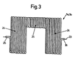
- FIG. 3 shows a flat heating mat 5a or 5b, which consists of a zigzag-shaped arrangement of a heating wire 23 covered with plastic.
- Each heating mat 5a, 5b is inserted between the pipeline 1 and the saddle pieces 3, 4 in such a way that the two legs 24 between the outer diameter of the pipeline 1 and the contact surfaces 19 of the saddle pieces 3, 4 and the web 25 each in one of the gaps 7 comes to rest.
- the two legs 24 thus surround the pipeline 1 at the full circumference, the end of the leg 24 of a heating mat 5a or 5b forming a mutual overlap with the web 25 of the other heating mat 5b or 5a arranged in the gap 7.
- the branch line 21 is connected to the connecting piece 20 and then the connection between the pipeline 1 and the branch line 21 is made by the tool 10 by punching out or drilling out the hole 9, the medium passes through the hole 9 and the ring channel 22 to the branch line 21.
- the seal between the guide part 12 and the nozzle 8 enables the hole to be created even under pressure of the flow medium.
- the tool is fastened by means of the screw 16 and the through hole 14 is closed completely tightly with the cover cap 17.
- the saddle pieces can also e.g. by means of an adhesive connection or a detachable connection e.g. can be connected to the pipeline by mutual bracing by means of screws or wedges, whereby a perfect seal must be guaranteed by arranging seals on both sides of the annular chamber and in the joints of the saddle pieces along the pipeline.
- the connection fitting can also be formed in one piece with a hinged hinge for radical attachment to the pipeline.
Landscapes
- Engineering & Computer Science (AREA)
- Mechanical Engineering (AREA)
- General Engineering & Computer Science (AREA)
- Branch Pipes, Bends, And The Like (AREA)
- Protection Of Pipes Against Damage, Friction, And Corrosion (AREA)
- Joints Allowing Movement (AREA)
- Cable Accessories (AREA)
Description
- Die Erfindung betrifft ein Anschlussformstück zur Erstellung eines Abzweiganschlusses wie es im Oberbegriff von Anspruch 1 gekennzeichnet ist.
- Für den Anschluss von Zweigleitungen kleineren Durchmessers an bestehenden Hauptrohrleitungen ist es bekannt, auf die Hauptrohrleitung Formstücke - sogenannte Anbohrformstückeaufzusetzen und durch Anbohren der Hauptleitung die Verbindung mit der am Formstück angeschlossenen Zweigleitung herzustellen. Derartige Anbohrformstücke sind meist zweiteilig ausgebildet, wobei deren beide Sattelhälften z.B. durch Keile zusammengehalten (CH-A-464 260 bzw. DE-A-2 035 667) oder bei Kunststoffleitungen durch eine Schweissverbindung mit der Hauptrohrleitung verbunden werden (CH-A-528 697 bzw. DE-A-2 514 827).
- Bei allen bekannten Anbohrformstücken ist der Anschlussstutzen für die Zweigleitung an dem für die Anbohrwerkzeuge vorgesehenen, radial zur Hauptrohrleitung verlaufenden Stutzen angeordnet. Eine derartige Anordnung ermöglicht bei einer kompakten Bauweise jedoch nur den Anschluss von Zweigleitungen, deren Querschnitt bzw. Durchmesser wesentlich kleiner ist als der der Hauptrohrleitung.
- Abzweigleitungen mit einem mindestens gleich grossen oder geringfügig kleinerem Durchmesser wie die Hauptrohrleitung können zwar mit handelsüblichen T-Formstücken hergestellt werden, doch ist dies aufwendig und dann nicht möglich, wenn die Abzweigung unter Aufrechterhaltung des Betriebsdruckes des durchgeleiteten Mediums erstellt werden soll. In diesem Zusammenhang ist ein Anschlussformstück bekanntgeworden (DE-U-1 716 598), welches einen Ringkanal zum Weiterleiten des Druckmediums aufweist.
- Aufgabe der vorliegenden Erfindung ist die Schaffung eines Anschluss-Formstückes der eingangs genannten Art, mittels welchem auch während des Medium-Durchflusses unter Betriebsdruck eine Zweigleitung an eine Rohrleitung anschliessbar ist, deren Durchmesser auch gleich gross oder etwas kleiner sein kann wie der der Rohrleitung ist.
- Ausserdem soll das Formstück einfach bzw. kunststoffgerecht gestaltbar und absolut dicht mit der Rohrleitung verbindbar sein.
- Erfindungsgemäss wird dies durch die im kennzeichnenden Teil des Anspruches 1 angeführten Merkmale gelöst.
- Weitere vorteilhafte Ausgestaltungen der Erfindung sind in den abhängigen Ansprüchen gekennzeichnet.
- Durch die erfindungsgemässe Anordnung des Anschlußstutzens für die Abzweigleitung auf der dem Werkzeug gegenüberliegenden Rohrumfangsseite und die Verbindung der beiden Stutzen mit einem Ringkanal ist es möglich auch bei Rohrleitungen im grossen Durchmesserbereich Abzweigleitungen anzuschliessen, welche gleiche oder annähernd gleiche Durchmesser aufweisen wie die Rohrleitung selbst, wobei ein Anschliessen der Abzweigleitung auch bei einer unter Druck stehenden Rohrleitung gewährleistet ist.
- Das für die Erzeugung des entsprechend grossen Loches erforderliche Werkzeug benötigt dadurch nur einen kurzen Verstell-Weg, wodurch der Stutzen für das Werkzeug trotz dessen grossen Durchmessers kurz ausgebildet sein kann. Daraus ergeben sich die Vorteile einer einfachen, materialsparenden Formgestaltung bei einer geringen Bauhöhe, welche insbesonders für die Herstellung des Anschlussformstückes aus Kunststoff im Spritzgussverfahren geeignet ist.
- Durch die vorteilhafte Ausbildung des Formteiles mit zwei Sattelstücken gemäss Anspruch 2 wird eine einfache Montage erreicht, wobei eine lösbare als auch eine nicht lösbare Verbindung möglich ist. Durch die Befestigung der Sattelstücke an der Rohrleitung gemäss Anspruch 3 mittels einer Schweissverbindung wird eine besonders dichte und feste Verbindung erreicht. Die Merkmale der Ansprüche 3 bis 5 für sich allein sind durch die Ältere Anmeldung EP-A-0 076 460 vorweggenommen. Ferner weisen die am Gegenstand dieser älteren Anmeldung angeordneten beiden Sattelstücke jeweils zwei umfangsseitig angeordnete Auflageflächen auf, die zusammen mit dem Außendurchmesser des Rohres und den Schenkeln der Heizmatten einen Ringkanal bilden. Mindestens eines der Sattelstücke ist als Abzweigstück für ein Abzweigrohr oder alternativ hierzu, als Anbohrformstück ausgebildet.
- Die Erfindung ist in beiliegenden Zeichnungen anhand eines Ausführungsbeispieles dargestellt und nachfolgend beschrieben.
- Es zeigen:
- Fig. 1 einen Querschnitt eines mit einer Rohrleitung verschweissten Anschlussformstückes,
- Fig. 2 einen Schnitt entlang der Linie 11-11 von Fig. 1 und
- Fig. 3 eine Draufsicht der Heizmatte im flachgelegten Zustand.
- Auf eine Rohrleitung 1 aus Kunststoff ist ein Anschlussformstück 2 angeordnet, welches zwei Sattelstücke 3 und 4 aufweist. Die beiden Sattelstücke 3 und 4 sind mit der Rohrleitung 1 und auch gegenseitig mittels zwei, vorzugsweise identischen Heizmatten 5a, 5b verschweisst, von denen jede einem der Sattelstücke 3 oder 4 zugeordnet ist.
- Die halbschalenförmig ausgebildeten Sattelstücke 3, 4 sind an ihren seitlichen Enden mit je einem Flansch 6a, 6b versehen, wobei die sich jeweils gegenüberliegenden Flansche 6a, 6b einen in Längsrichtung der Rohrleitung 1 verlaufenden Spalt 7 bilden, welcher vorzugsweise tangential oder annähernd tangential zum Aussendurchmesser der Rohrleitung 1 angeordnet ist.
- Das Sattelstück 3 weist einen Stutzen 8 auf, in welchem ein Werkzeug 10 zur Erzeugung eines Loches 9 in der Rohrleitung 1 angeordnet ist. Im gezeigten Ausführungsbeispiel ist das Werkzeug als Loch-Stanz-Werkzeug 10 ausgebildet welches aus einem Schneideteil 11 und einem Führungsteil 12 besteht. In der linken Bildhälfte von Fig. 1 ist das Werkzeug 10 in der untersten Schneid-Lage dargestellt, wobei in das Führungsteil 12 eine Stange 13 eingeschraubt ist, welche in einen Durchgangsloch 14 eines mit dem Stutzen 8 fest verbundenen Deckelteiles 15 geführt ist. Das Loch 9 wird durch einen Druck oder Schlag auf das äussere Ende der Stange 13 mittels eines Schlagwerkzeuges wie z.B. einem Hammer erzeugt.
- In der rechten Bildhälfte von Fig. 1 ist das werkzeug 10 nach der Locherzeugung in der oberen Ruhelage dargestellt.
- Hierbei ist anstatt der Stange 13 eine Schraube 16 in das Führungsteil 12 eingeschraubt, durch welche das Werkzeug 10 am Deckelteil 15 fest gehalten wird, wobei das Durchgangsloch 14 durch eine Abdeckkappe 17 dicht verschlossen ist.
- Das ausgestanzte Rohrteil 18 der Rohrleitung 1 wird durch das Werkzeug 10 mit angehoben und bleibt durch den Druck des Mediums in dieser Lage.
- Das Werkzeug kann auch als Fräs- oder Bohrwerkzeug ausgebildet sein, wobei dann z.B. die Stange 13 und das Durchgangsloch 14 ein Vorschubgewinde zur Erzeugung der Vorschubbewegung beim Drehen des Werkzeuges aufweisen, oder es sind getrennte Bohreinrichtungen auf den Stutzen aufsetzbar.
- Das Sattelstück 4 weist einen Anschlußstutzen 20 auf an welchem eine Abzweigleitung 21 durch eine nicht lösbare Verbindung z.B. eine Schweiss-oder Klebe-Verbindung oder durch eine lösbare Verbindung anschliessbar ist.
- Der Abzweigstutzen 21 ist somit auf der dem Stutzen 8 für das Werkzeug 10 gegenüberliegenden halben Rohrumfang radial zur Rohrleitung 1 angeordnet, wobei vorteilhafterweise beide Stutzen 8, 20 zueinander fluchtend angeordnet sind. Am Innendurchmesser der Sattelstücke 3, 4 sind zwischen zwei für die Verschweissung erforderlichen Auflageflächen 19 Ausnehmungen angeordnet, welche zusammen einen die beiden Stutzen 8 und 20 verbindenden Ringkanal 22 bilden.
- Die Fig. 3 zeigt eine flachgelegte Heizmatte 5a bzw. 5b, welche aus einer zick-zack-förmigen Anordnung eines mit Kunststoff ummantelten Heizdrahtes 23 besteht.
- Der Heizdraht 23 ist so gewickelt, dass die Heizmatte U-förmig mit zwei Schenkeln 24 und einem Steg 25 ausgebildet ist. Die beiden abstehenden Enden 26 des Heizdrahtes jeder Heizmatte stehen im fertig montierten Zustand unter den Sattelstücken hervor oder werden auf ein Steckelement geführt. Mittels Klemm- oder Steckverbindungen wird die Wicklung an eine Strornquette angeschlossen (siehe auch Fig. 2).
- Jede Heizmatte 5a, 5b wird so zwischen der Rohrleitung 1 und den Sattelstücken 3, 4 eingelegt, dass jeweils die beiden Schenkel 24 zwischen dem Aussendurchmesser der Rohrleitung 1 und den Auflageflächen 19 der Sattelstücke 3, 4 und der Steg 25 jeweils in einem der Spalte 7 zu liegen kommt. Die beiden Schenkel 24 umschliessen somit die Rohrleitung 1 am vollen Umfang wobei das Ende des Schenkels 24 einer Heizmatte 5a bzw. 5b mit dem im Spalt 7 angeordneten Steg 25 der anderen Heizmatte 5b bzw. 5a eine gegenseitige Ueberdeckung bildet. Dies ergibt zwei vollständige Umfangsschweissverbindungen zwischen der Rohrleitung und den Sattelstücken im Bereich der Auflageflächen und zwei durchgehende Längsschweissverbindungen zwischen den beiden Sattelstücken 3, 4 in den Spalten 7, so dass der Ringkanal 22 nach aussen vollkommen abgedichtet ist.
- Nach dem Erstellen der Schweissverbindung der beiden Sattelstücke mit der Rohrleitung mittels durch die Heizmatten geleiteten Strom wird an den Anschlußstutzen 20 die Abzweigleitung 21 angeschlossen und anschliessend durch das Werkzeug 10 durch Ausstanzen oder Ausbohren des Loches 9 die Verbindung zwischen Rohrleitung 1 und der Abzweigleitung 21 hergestellt, wobei das Medium durch das Loch 9 und den Ringkanal 22 zur Abzweigleitung 21 gelangt. Die Abdichtung zwischen dem Führungsteil 12 und dem Stutzen 8 ermöglicht die Erstellung des Loches auch unter Druck des Durchflussmediums. Nach der Herstellung des Loches 9 wird das Werkzeug mittels der Schraube 16 befestigt und das Durchgangsloch 14 mit der Abdeckkappe 17 vollkommen dicht verschlossen.
- Neben der beschriebenen Schweissverbindung können die Sattelstücke auch z.B. mittels einer Klebeverbindung oder einer lösbaren Verbindung z.B. durch gegenseitiges Verspannen mittels Schrauben oder Keilen mit der Rohrleitung verbunden werden, wobei durch Anordnung von Dichtungen beidseitig der Ringkammer umfangsmässig und in den Trennfugen der Sattelstücke längs der Rohrleitung eine einwandfreie Abdichtung gewährleistet sein muss. Das Anschlussformstück kann auch einstückig mit einem Aufklapp-Scharnier zum radikalen Aufstecken auf die Rohrleitung ausgebildet sein.
Claims (7)
Priority Applications (1)
| Application Number | Priority Date | Filing Date | Title |
|---|---|---|---|
| AT83103859T ATE21445T1 (de) | 1982-04-29 | 1983-04-20 | Anschluss-formstueck. |
Applications Claiming Priority (2)
| Application Number | Priority Date | Filing Date | Title |
|---|---|---|---|
| CH2638/82 | 1982-04-29 | ||
| CH2638/82A CH655374A5 (de) | 1982-04-29 | 1982-04-29 | Anschluss-formstueck. |
Publications (2)
| Publication Number | Publication Date |
|---|---|
| EP0093328A1 EP0093328A1 (de) | 1983-11-09 |
| EP0093328B1 true EP0093328B1 (de) | 1986-08-13 |
Family
ID=4238258
Family Applications (1)
| Application Number | Title | Priority Date | Filing Date |
|---|---|---|---|
| EP19830103859 Expired EP0093328B1 (de) | 1982-04-29 | 1983-04-20 | Anschluss-Formstück |
Country Status (6)
| Country | Link |
|---|---|
| US (1) | US4515177A (de) |
| EP (1) | EP0093328B1 (de) |
| JP (1) | JPS591897A (de) |
| AT (1) | ATE21445T1 (de) |
| CH (1) | CH655374A5 (de) |
| DE (1) | DE3365248D1 (de) |
Cited By (1)
| Publication number | Priority date | Publication date | Assignee | Title |
|---|---|---|---|---|
| DE19900556C1 (de) * | 1999-01-09 | 2000-06-29 | Vaf Voigt Armaturenfabrikation | Anschlußvorrichtung zur Herstellung eines Anschlusses an eine Rohrverbindung für fluide Medien |
Families Citing this family (18)
| Publication number | Priority date | Publication date | Assignee | Title |
|---|---|---|---|---|
| ATE32132T1 (de) * | 1984-08-08 | 1988-02-15 | Fischer Ag Georg | Anbohrformstueck aus schweissbarem kunstoff. |
| FR2571121B1 (fr) * | 1984-09-28 | 1987-04-03 | Gautier Emile | Manchon de piquage pour intervention sur une canalisation en matiere synthetique en charge |
| US4883085A (en) * | 1988-09-15 | 1989-11-28 | Mueller Company | Method of installing a stopper in a fitting and apparatus therefor |
| US4985779A (en) * | 1989-09-19 | 1991-01-15 | Intergraph Corporation | Improved method and apparatus for generating halftone images |
| DE4127350C2 (de) * | 1991-08-19 | 1994-06-30 | Friatec Keramik Kunststoff | Stutzenarmatur |
| US5348045A (en) * | 1992-02-15 | 1994-09-20 | Manibs Spezialarmaturen Gmbh & Co. Kg | Pipe clamp for plastic supply pipelines, particularly a tapping clamp |
| DE4217982C2 (de) * | 1992-05-30 | 1994-06-30 | Friatec Keramik Kunststoff | Ventil-Anbohrarmatur |
| US5321233A (en) * | 1992-09-15 | 1994-06-14 | Northern Illinois Gas | Electrofusion fitting and sealing method for distribution line |
| US5269340A (en) * | 1992-10-15 | 1993-12-14 | Institute Of Gas Technology | Combined hot tap pipe cutter and gate valve for plastic pipe |
| US5577528A (en) * | 1994-11-18 | 1996-11-26 | Southern California Gas Company | Apparatus for upgrade or repair of in-service pipelines |
| DE4445005C1 (de) * | 1994-12-16 | 1996-05-23 | Reich Kg | Verfahren und vorgefertigte Teile zur Herstellung von Rohrabzweigungen |
| DE19504698C2 (de) * | 1995-02-13 | 2000-06-29 | Friatec Keramik Kunststoff | Anbohrarmatur |
| DE19623353C1 (de) * | 1996-06-12 | 1998-01-29 | Manibs Spezialarmaturen | Schelle für ein aus thermisch schweißfähigem Material bestehendes Leitungsrohr |
| IL122286A (en) * | 1996-11-30 | 2002-02-10 | Friatec Ag | Hose perforation valve |
| DK1027553T3 (da) * | 1997-11-03 | 2002-06-17 | Da Kunststoff Gmbh | Påsvejsbar skal til et ledningsrør bestående af termisk svejsebart materiale |
| JP4398162B2 (ja) * | 2002-12-19 | 2010-01-13 | 株式会社水研 | バルブ挿入工法 |
| CN102784966A (zh) * | 2012-07-20 | 2012-11-21 | 河南中拓石油工程技术股份有限公司 | 一种不用阀门带压开孔接支线工艺 |
| CN116428439B (zh) * | 2023-06-14 | 2023-09-08 | 齐齐哈尔大学 | 一种管道分流连接装置 |
Citations (1)
| Publication number | Priority date | Publication date | Assignee | Title |
|---|---|---|---|---|
| EP0076460A1 (de) * | 1981-10-02 | 1983-04-13 | Georg Fischer Aktiengesellschaft | Schweissverbindung für Kunststoffrohre |
Family Cites Families (20)
| Publication number | Priority date | Publication date | Assignee | Title |
|---|---|---|---|---|
| US1570887A (en) * | 1924-12-29 | 1926-01-26 | William B Graves | Pipe connection |
| US2309253A (en) * | 1941-07-12 | 1943-01-26 | Dresser Mfg Company | Pipe fitting |
| DE1716598U (de) * | 1955-10-13 | 1956-02-09 | Brueder Mannesmann G M B H | Uberschieber fuer rohrleitungen. |
| NL236188A (de) * | 1958-02-17 | |||
| US3240226A (en) * | 1962-05-31 | 1966-03-15 | Mid Atlantic Plastics Corp | Self-tapping service valve fitting |
| BE701230A (de) * | 1966-07-11 | 1968-01-11 | ||
| CH503542A (de) * | 1969-09-01 | 1971-02-28 | Fischer Ag Georg | Rohranbohrer |
| US3833020A (en) * | 1970-02-24 | 1974-09-03 | Pipe Line Development Co | Apparatus for plugging pipe |
| US3692044A (en) * | 1971-01-18 | 1972-09-19 | Sloane Mfg Co R & G | Tapping tee |
| US3867964A (en) * | 1973-02-01 | 1975-02-25 | Pipe Line Development Co | Apparatus for plugging pipe |
| US4034777A (en) * | 1973-09-10 | 1977-07-12 | Sven Runo Vilhelm Gebelius | Apparatus to pierce a fluid-transport pipe and control the fluid-flow therefrom |
| NL161565C (nl) * | 1973-09-14 | 1980-02-15 | Polva Nederland Bv | Aftakking van een hoofdleiding uit kunststof naar een dienstleiding. |
| CH570577A5 (de) * | 1974-05-10 | 1975-12-15 | Fischer Ag Georg | |
| JPS5218A (en) * | 1975-06-23 | 1977-01-05 | Seihachi Matsumoto | Fittings for mounting portion material that is penetration fitted to angle body |
| US4174926A (en) * | 1977-06-06 | 1979-11-20 | World Energy Systems | Windmill pump drive system |
| US4258742A (en) * | 1979-04-03 | 1981-03-31 | Phillips Petroleum Company | Tapping apparatus |
| US4313053A (en) * | 1980-01-02 | 1982-01-26 | Von Roll A.G. | Welding sleeve of thermoplastic material |
| EP0035750B1 (de) * | 1980-03-10 | 1984-02-08 | Georg Fischer Aktiengesellschaft | Schweissverbindung für Kunststoffrohre |
| CH648393A5 (de) * | 1980-08-29 | 1985-03-15 | Werner Sturm | Elektro-schweissmuffe aus einem thermoplast zum verbinden von leitungselementen aus thermoplast. |
| US4355656A (en) * | 1981-04-28 | 1982-10-26 | The Pipe Line Development Company | Pipeline plug and bypass |
-
1982
- 1982-04-29 CH CH2638/82A patent/CH655374A5/de not_active IP Right Cessation
-
1983
- 1983-04-20 EP EP19830103859 patent/EP0093328B1/de not_active Expired
- 1983-04-20 DE DE8383103859T patent/DE3365248D1/de not_active Expired
- 1983-04-20 AT AT83103859T patent/ATE21445T1/de not_active IP Right Cessation
- 1983-04-26 US US06/488,650 patent/US4515177A/en not_active Expired - Fee Related
- 1983-04-28 JP JP58076056A patent/JPS591897A/ja active Granted
Patent Citations (1)
| Publication number | Priority date | Publication date | Assignee | Title |
|---|---|---|---|---|
| EP0076460A1 (de) * | 1981-10-02 | 1983-04-13 | Georg Fischer Aktiengesellschaft | Schweissverbindung für Kunststoffrohre |
Cited By (1)
| Publication number | Priority date | Publication date | Assignee | Title |
|---|---|---|---|---|
| DE19900556C1 (de) * | 1999-01-09 | 2000-06-29 | Vaf Voigt Armaturenfabrikation | Anschlußvorrichtung zur Herstellung eines Anschlusses an eine Rohrverbindung für fluide Medien |
Also Published As
| Publication number | Publication date |
|---|---|
| DE3365248D1 (en) | 1986-09-18 |
| EP0093328A1 (de) | 1983-11-09 |
| CH655374A5 (de) | 1986-04-15 |
| US4515177A (en) | 1985-05-07 |
| ATE21445T1 (de) | 1986-08-15 |
| JPS6327599B2 (de) | 1988-06-03 |
| JPS591897A (ja) | 1984-01-07 |
Similar Documents
| Publication | Publication Date | Title |
|---|---|---|
| EP0093328B1 (de) | Anschluss-Formstück | |
| EP0076460B1 (de) | Schweissverbindung für Kunststoffrohre | |
| DE3246327C2 (de) | Vorrichtung zur Verbindung zweier Rohrenden | |
| EP0170845B1 (de) | Anbohrformstück zum Anschluss einer Abzweigleitung | |
| EP0170844B1 (de) | Anbohrformstück aus schweissbarem Kunstoff | |
| DE2518001A1 (de) | Elastische dichtung fuer rohrverbindungen | |
| DE3217069A1 (de) | Rohrverbindung | |
| DE69102246T2 (de) | Kupplung. | |
| DE4105266C2 (de) | ||
| DE8910407U1 (de) | Rohrstück und zugehörender Elektroschweißfitting | |
| DE9107311U1 (de) | Schweißmuffe | |
| EP0089638B1 (de) | Durchgangskupplung für Rohrleitungen oder Schläuche | |
| DE29713845U1 (de) | Preßfitting für Kunststoffrohre, insbesondere Kunststoff-Metall-Verbundrohre | |
| DE3627393C1 (en) | Connection part for joining a water meter to a T-shaped pipe connection | |
| DE3334836C2 (de) | Muffenförmige Dichtschelle für Gasleitungen | |
| DE69100542T2 (de) | Muffenrohr aus Kunststoff sowie Herstellungsverfahren dafür. | |
| DE2611175A1 (de) | Chlauchbefestigungsvorrichtung | |
| EP0036535B1 (de) | Reparaturkupplung | |
| DE29512309U1 (de) | Vorrichtung zum Anbohren von Kunststoffrohren von Versorgungsleitungen | |
| DE19924825C2 (de) | Rohrleitungsverbindung | |
| DE9101646U1 (de) | Verbindungsbogen | |
| DE4009403A1 (de) | Rohrleitungskupplung, rohrleitung sowie verfahren zur montage einer rohrleitung | |
| DE3216682C2 (de) | Dichtungseinrichtung für Rohrverbindungen | |
| EP0733846B1 (de) | Vorrichtung zum Anbohren von Kunststoffrohren von Versorgunsleitungen | |
| DE3044513C2 (de) | Kupplung für eine Rohrsteckverbindung |
Legal Events
| Date | Code | Title | Description |
|---|---|---|---|
| PUAI | Public reference made under article 153(3) epc to a published international application that has entered the european phase |
Free format text: ORIGINAL CODE: 0009012 |
|
| 17P | Request for examination filed |
Effective date: 19830420 |
|
| AK | Designated contracting states |
Designated state(s): AT BE DE FR GB IT LU NL SE |
|
| GRAA | (expected) grant |
Free format text: ORIGINAL CODE: 0009210 |
|
| AK | Designated contracting states |
Kind code of ref document: B1 Designated state(s): AT BE DE FR GB IT LU NL SE |
|
| REF | Corresponds to: |
Ref document number: 21445 Country of ref document: AT Date of ref document: 19860815 Kind code of ref document: T |
|
| REF | Corresponds to: |
Ref document number: 3365248 Country of ref document: DE Date of ref document: 19860918 |
|
| ET | Fr: translation filed | ||
| ITF | It: translation for a ep patent filed | ||
| PLBE | No opposition filed within time limit |
Free format text: ORIGINAL CODE: 0009261 |
|
| STAA | Information on the status of an ep patent application or granted ep patent |
Free format text: STATUS: NO OPPOSITION FILED WITHIN TIME LIMIT |
|
| 26N | No opposition filed | ||
| PGFP | Annual fee paid to national office [announced via postgrant information from national office to epo] |
Ref country code: GB Payment date: 19930315 Year of fee payment: 11 |
|
| PGFP | Annual fee paid to national office [announced via postgrant information from national office to epo] |
Ref country code: BE Payment date: 19930316 Year of fee payment: 11 |
|
| PGFP | Annual fee paid to national office [announced via postgrant information from national office to epo] |
Ref country code: FR Payment date: 19930317 Year of fee payment: 11 Ref country code: DE Payment date: 19930317 Year of fee payment: 11 |
|
| PGFP | Annual fee paid to national office [announced via postgrant information from national office to epo] |
Ref country code: LU Payment date: 19930318 Year of fee payment: 11 |
|
| PGFP | Annual fee paid to national office [announced via postgrant information from national office to epo] |
Ref country code: SE Payment date: 19930322 Year of fee payment: 11 |
|
| PGFP | Annual fee paid to national office [announced via postgrant information from national office to epo] |
Ref country code: AT Payment date: 19930323 Year of fee payment: 11 |
|
| ITTA | It: last paid annual fee | ||
| PGFP | Annual fee paid to national office [announced via postgrant information from national office to epo] |
Ref country code: NL Payment date: 19930430 Year of fee payment: 11 |
|
| EPTA | Lu: last paid annual fee | ||
| PG25 | Lapsed in a contracting state [announced via postgrant information from national office to epo] |
Ref country code: LU Free format text: LAPSE BECAUSE OF NON-PAYMENT OF DUE FEES Effective date: 19940420 Ref country code: GB Effective date: 19940420 Ref country code: AT Effective date: 19940420 |
|
| PG25 | Lapsed in a contracting state [announced via postgrant information from national office to epo] |
Ref country code: SE Effective date: 19940421 |
|
| PG25 | Lapsed in a contracting state [announced via postgrant information from national office to epo] |
Ref country code: BE Effective date: 19940430 |
|
| BERE | Be: lapsed |
Owner name: GEORG FISCHER A.G. Effective date: 19940430 |
|
| PG25 | Lapsed in a contracting state [announced via postgrant information from national office to epo] |
Ref country code: NL Effective date: 19941101 |
|
| GBPC | Gb: european patent ceased through non-payment of renewal fee |
Effective date: 19940420 |
|
| NLV4 | Nl: lapsed or anulled due to non-payment of the annual fee | ||
| PG25 | Lapsed in a contracting state [announced via postgrant information from national office to epo] |
Ref country code: FR Effective date: 19941229 |
|
| PG25 | Lapsed in a contracting state [announced via postgrant information from national office to epo] |
Ref country code: DE Effective date: 19950103 |
|
| EUG | Se: european patent has lapsed |
Ref document number: 83103859.1 Effective date: 19941110 |
|
| REG | Reference to a national code |
Ref country code: FR Ref legal event code: ST |