EP0093318B1 - Entschwartungsmaschine - Google Patents
Entschwartungsmaschine Download PDFInfo
- Publication number
- EP0093318B1 EP0093318B1 EP83103828A EP83103828A EP0093318B1 EP 0093318 B1 EP0093318 B1 EP 0093318B1 EP 83103828 A EP83103828 A EP 83103828A EP 83103828 A EP83103828 A EP 83103828A EP 0093318 B1 EP0093318 B1 EP 0093318B1
- Authority
- EP
- European Patent Office
- Prior art keywords
- knife
- machine
- arms
- feed roll
- derinding
- Prior art date
- Legal status (The legal status is an assumption and is not a legal conclusion. Google has not performed a legal analysis and makes no representation as to the accuracy of the status listed.)
- Expired
Links
Images


Classifications
-
- A—HUMAN NECESSITIES
- A22—BUTCHERING; MEAT TREATMENT; PROCESSING POULTRY OR FISH
- A22C—PROCESSING MEAT, POULTRY, OR FISH
- A22C17/00—Other devices for processing meat or bones
- A22C17/12—Apparatus for cutting-off rind
Definitions
- the invention relates to a derinding machine according to the features of the preamble of claim 1.
- derinding machines are already known, e.g. B. by DE-B-1 278 873. They have proven themselves in practice and in particular allow easy removal and installation of the blade holder. However, these previously known machines can still be improved with regard to their usability and structural complexity. It is not uncommon for these derinding machines to have various operating levers, so that a first and a further lever may have to be operated first to set the removal position of the knife.
- the invention proposes the measures of the characterizing part of the first claim in a derinding machine of the type mentioned at the beginning.
- the deflection knife or its blade holder can be adjusted with the aid of a single lever, and even up to a lifting position for the blade holder.
- the knife adjustment mechanism is accordingly easy to use and its structure is simple and compact.
- a derinding machine with a pulling roller and an adjustable blade holder which has suspension arms which cooperate with guide stops as well as pressurizing elements.
- this derinding machine not only are the guide stops and the pressurizing elements arranged on the same side of the suspension arms, but the blade holder can only be removed after a special holding bolt has been removed.
- a particularly expedient embodiment of the invention results from the fact that the knife can be lifted off the pull roller in different rind positions, and that a run-up curve for a run-up element is attached to the guide stop, which can be moved relative to the run-up curve by means of the eccentric.
- the knife or the blade holder can be easily adjusted to different rind pull positions with the aid of the eccentric.
- the knife or the blade holder is already adjustable in rind pulling positions, but an additional stop adjustable by means of a further hand lever is required for this. Further refinements of the invention are listed in the subclaims.
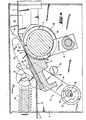
- a bacon derinding machine 1 (FIG. 1) has a standing housing 2, on the upper area of which the devices for bacon derinding are located. These are essentially a pulling roller 3, a cutoff knife 5 fastened in a blade holder 4 and an adjustment device designated as a whole by means of which the cutoff knife 5 can be brought into different positions relative to the pulling roller 3.
- the waste material 24, 25 is fed via a feed table 7 into the area of the pull roller 3 and also into the area of the spring blade 5.
- the separated rind 25 is then removed below the knife 5, while the bacon 26 reaches a discharge table 8 above the knife 5 (FIG. 5).
- Below the pulling roller 3, which has corrugations 30, a stripper 9 engaging in grooves 29 can still be seen, through which rind 25 adhering to the pulling roller 3 can be scraped off.
- the chopping knife 5 is pressurized towards the pulling roller 3 and lifts off the pulling roller 3 from the pulling roller 3 according to the thickness of the rind 25 (FIG. 5).
- the knife 5 is held at a very short distance from the surface of the pulling roller before the material to be quenched 25, 26 is fed.
- 3 support rings 10 are provided on both ends of the pull roller, on which corresponding support elements of the blade holder 4 rest in the starting position.
- the blade holder 4 in the starting position (Fig. 4) and in a lifting position (Fig. 6) are brought.
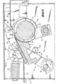
- a so-called rind pull position is also provided in the exemplary embodiment (cf. FIG. 5), in which the knife 5 is at a certain distance 27 from the pull roller 3.
- the mechanics of this adjusting device 6 can be seen particularly well in FIGS. 4 to 6.
- the parts shown here are located at one end of the pull roller 3 and are symmetrically present on the opposite side in the same way.
- suspension arms 11 are provided, which are pivoted simultaneously by an eccentric 12 and are also displaceable in the longitudinal direction.
- the eccentric 12 can be adjusted by means of a hand lever 13 (FIGS. 2 and 3).
- the eccentrics 12 provided on the two housing sides with the suspension arms 11 attached to them are connected to one another via an eccentric shaft 14.
- a first guide stop 16 formed by a support bolt 15 is also provided in the area of the suspension arms 11.
- pressure elements 17 act on the suspension arms 11.
- the bearing 28 of the eccentric 12 is located below, laterally offset from the pulling roller 3 and the suspension arms 11 extend at an angle of approximately 35 ° to the pulling roller 3, the provided receiving recesses 18 for suspension bolts 19 of the blade holder 4 being approximately at the Top of the pull roller 3 are.
- the suspension arms 11 are thus arranged essentially tangentially at a distance from the pull roller 3.
- the support pin 15 is located on the longitudinal side of the suspension arm 11 facing the pull roller 3, while on the other, opposite side, approximately at the level of the recesses 18, the pressure-applying element 17 engages.
- the suspension arms 11 are raised relative to the first guide stops 16 of the support bolts 15.
- the suspension arms 11 are located next to the first guide stop 16 with a knife 5 lying approximately on the pull roller 3 (Fig. 4 / Fig. 5). If the eccentric 12 is now rotated into the position shown in FIG.
- the support bolts 15 practically form rocker-like first guide stops 16, about which the suspension arms 11 tilt when the eccentric 12 is adjusted into the lifting position.
- the upper ends of the support arms 11 holding the blade holder 4 pivot against the pressurization by the element 17 (arrow Pf 2).
- the knife 5 with the blade holder 4 thereby lifts off the pull roller 3 and is finally pivoted into the release position.
- the blade holder 4 can then be removed obliquely upwards.
- the eccentric 12 can be rotated by approximately 90 ° in the work starting position (FIG. 4).
- the knife 5 in this bacon derinding machine 1 can also be adjusted in the rind pull position.
- the shift in position resulting from the eccentric bearing 12 is also utilized in the longitudinal direction of the suspension arms 11.
- the blade holder 4 runs onto a fixed run-up curve 20, which is arranged so that the Knife 5 is lifted to the desired extent from the pull roller 3 (Fig. 5).
- the blade holder 4 has side arches 21, approximately to the side of its working area, which carry overrun elements 22 arranged at a distance from the hanging bolts 19.
- the casserole elements 22 are formed in the exemplary embodiment by caster rollers.
- the position of the run-up curve 20 and the displacement path predetermined by the eccentric 12 are matched to the intended stroke of the knife 5 for the rind pull positions. This could easily be changed if necessary by exchanging the second guide stops 23 with other run-up curves 20.
- the pressurizing elements 17 engaging approximately at the free, upper end of the suspension arms 11 are connected to pressure elements, in the exemplary embodiment spring assemblies made of plate springs 24.
- the preload of the cutoff knife 5 in the direction of the pull roller 3 can, if necessary, be changed by the number, type or adjustment of the plate springs 24. It should also be mentioned that the casserole elements 22 can also be provided directly on the suspension arms 11, if appropriate, with appropriate design and mounting of the blade holder 4, and z. B. be formed by its free ends itself.
- the following sequence of functions results when the hand lever 13 is actuated for the eccentrics 12: starting from the lifting position (FIG. 6), the blade holder 4 with its hanging bolts 19 is first inserted into the receiving recesses 18 of the suspension arms 11. Subsequently, the eccentric 12 is rotated clockwise by approximately 90 °, the suspension arms 11 being moved about by the case of slight longitudinal displacement movements Tilt the support bolt 15 until corresponding support elements rest on the blade holder 4 on the side support rings 10 of the pull roller 3. The abrupt knife 5 is then in the normal working position (FIG. 4).
- the suspension arms are moved in accordance with the arrow Pf 1 until the run-up elements 22 hit the run-up curves 20.
- the cutoff knife 5 is then lifted off the pulling roller 3 in accordance with the course of the run-up curve 20.
- the maximum rind draft position is shown in FIG would be at a greater distance.
- an angle of rotation of the eccentric 12 of approximately 180 ° is provided between the raised position and the intended maximum rind pull position. Twist stops are arranged at these end positions.
Landscapes
- Life Sciences & Earth Sciences (AREA)
- Engineering & Computer Science (AREA)
- Wood Science & Technology (AREA)
- Zoology (AREA)
- Food Science & Technology (AREA)
- Pharmaceuticals Containing Other Organic And Inorganic Compounds (AREA)
- Seeds, Soups, And Other Foods (AREA)
- Centrifugal Separators (AREA)
- Apparatuses For Bulk Treatment Of Fruits And Vegetables And Apparatuses For Preparing Feeds (AREA)
- Indole Compounds (AREA)
- Sewing Machines And Sewing (AREA)
- Folding Of Thin Sheet-Like Materials, Special Discharging Devices, And Others (AREA)
- Details Of Cutting Devices (AREA)
Description
- Die Erfindung betrifft eine Entschwartungsmaschine entsprechend den Merkmalen des Oberbegriffs von Anspruch 1.
- Derartige Entschwartungsmaschinen sind bereits bekannt, z. B. durch DE-B-1 278 873. Sie haben sich in der Praxis bewährt und ermöglichen insbesondere ein einfaches Aus- und Einbauen des Klingenhalters. Bezüglich der Bedienbarkeit und des baulichen Aufwandes sind diese vorbekannten Maschinen jedoch noch verbesserungsfähig. Nicht selten haben diese Entschwartungsmaschinen verschiedene Bedienhebel, so daß gegebenenfalls für die Einstellung der Entnahmestellung des Messers zunächt ein erster und ein weiterer Hebel bedient werden muß.
- Es besteht daher die Aufgabe, eine Entschwartungsmaschine der eingangs erwähnten Art mit einfacher Verstellmechanik für das Messer sowie bequemer Bedienungsmöglichkeit zu schaffen.
- Zur Lösung dieser Aufgabe schlägt die Erfindung bei einer Entschwartungsmaschine der eingangs erwähnten Art die Maßnahmen des Kennzeichnungsteiles des ersten Anspruches vor. Bei einer solchen Maschine kann das Verstellen des Abschwartmessers bzw. seines Klingenhalters mit Hilfe eines einzigen Hebels erfolgen, und zwar auch bis in eine Aushebestellung für den Klingenhalter. Die Messer-Verstellmechanik ist dementsprechend leicht zu handhaben und ihr Aufbau einfach und kompakt. Außerdem ergeben sich nicht nur günstige Hebelverhältnisse, sondern die gesamte Verstelleinrichtung hat nur eine vergleichsweise geringe Bauhöhe, die sich im wesentlichen an der Länge der Aufhängearme orientiert.
- Durch die FR-A-1 358 888 ist zwar auch bereits eine Entschwartungsmaschine mit einer Zugwalze und einem verstellbaren Klingenhalter bekannt, der mit Führungsanschlägen zusammenarbeitende Aufhängearme sowie Druckbeaufschlagungselemente aufweist. Bei dieser Entschwartungsmaschine sind jedoch nicht nur die Führungsanschläge und die Druckbeaufschlagungselemente auf der gleichen Seite der Aufhängearme angeordnet, sondern der Klingenhalter ist nur nach Entfernen eines besonderen Haltebolzens abnehmbar.
- Weiterbildungen der Erfindung sind in den Unteransprüchen aufgeführt.
- Eine besonders zweckmäßige Ausgestaltung der Erfindung gemäß Anspruch 4 ergibt sich dadurch, daß das Messer in unterschiedliche Schwartenstellungen von der Zugwalze abhebbar ist, und daß dazu am Führungsanschlag eine Auflaufkurve für ein Auflaufelement angebracht ist, welches mittels des Exzenters gegenüber der Auflaufkurve bewegbar ist. Durch diese Ausgestaltung kann man das Messer bzw. den Klingenhalter mit Hilfe des Exzenters in unterschiedliche « Schwartenzugstellungen auf einfache Weise einstellen. Bei der eingangs erwähnten Entschwartungsmaschine nach DE-B-1 278 873 ist zwar auch bereits das Messer bzw. der Klingenhalter in Schwartenzugstellungen verstellbar, jedoch ist dazu ein zusätzlicher, über ein weiteren Handhebel verstellbarer Anschlag erforderlich. Weitere Ausgestaltungen der Erfindung sind in den Unteransprüchen aufgeführt.
- Nachstehend wird die Erfindung anhand der Zeichnung noch näher erläutert. Es zeigt :
- Figur 1 eine Seitenansicht einer im Schnitt gehaltenen bzw. halbseitig dargestellten Speckentschwartungsmaschine,
- Figur 2 eine perspektivische Rückansicht einer Speckentschwartungsmaschine bei abgenommenem Klingenhalter und abgenommenem Ablauftisch,
- Figur 3 eine Aufsicht der in Fig. 2 gezeigten Maschine, jedoch mit eingesetztem Ablauftisch,
- Figur 4 eine Schnittdarstellung gemäß Linie IV-IV in Fig. 2 einer nur zum Teil im Bereich der Zugwalze sowie des Messers dargestellte Entschwartungsmaschine mit in Arbeitsausgangsstellung befindlichem Klingenhalter,
- Figur 5 eine etwa Fig. 4 entsprechende Darstellung, hier jedoch mit in Schwartenzugstellung befindlichem Klingenhalter und
- Figur 6 eine den Fig. 4 und 5 entsprechende Darstellung, hier jedoch mit in Aushebestellung befindlichem Klingenhalter.
- Eine Speckentschwartungsmaschine 1 (Fig. 1) weist ein Standgehäuse 2 auf, an dessen oberen Bereich sich die Einrichtungen zum Speckentschwarten befinden. Es sind dies im wesentlichen eine Zugwalze 3, ein in einem Klingenhalter 4 befestigtes Abschwartmesser 5 sowie eine im ganzen mit 6 bezeichnete Verstelleinrichtung, mittels der das Abschwartmesser 5 in unterschiedliche Stellungen relativ zu der Zugwalze 3 gebracht werden kann. Das Abschwartgut 24, 25 wird über einen Zuführtisch 7 in den Bereich der Zugwalze 3 sowie auch in den Bereich des Abschwartmessers 5 geführt. Die abgetrennte Schwarte 25 wird dann unterhalb des Messers 5 abgeführt, während der Speck 26 oberhalb des Messers 5 zu einem Ablauftisch 8 gelangt (Fig. 5). Unterhalb der Zugwalze 3, welche Riffelungen 30 aufweist, ist noch ein in Nuten 29 eingreifender Abstreifer 9 zu erkennen, durch den an der Zugwalze 3 anhaftende Schwarte 25 abgestreift werden kann.
- Das Abschwartmesser 5 ist zu der Zugwalze 3 hin druckbeaufschlagt und hebt von der Zugwalze 3 während des Abschwartens entsprechend der Dicke der Schwarte 25 von der Zugwalze 3 ab (Fig. 5). Das Messer 5 wird vor dem Zuführen des Abschwartgutes 25, 26 mit ganz geringem Abstand zu der Zugwalzenoberfläche gehalten. Dazu sind an beiden Enden der Zugwalze 3 Auflageringe 10 (Fig. 3 und 4) vorgesehen, auf denen entsprechende Stützelemente des Klingenhalters 4 in Ausgangslage aufliegen.
- Durch die Verstelleinrichtung 6 kann einerseits der Klingenhalter 4 in Arbeitsausgangsstellung (Fig. 4) sowie in eine Aushebestellung (Fig. 6) gebracht werden. Außerdem ist im Ausführungsbeispiel noch eine sogenannte Schwartenzugstellung vorgesehen (vgl. Fig. 5), in der das Messer 5 zu der Zugwalze 3 einen gewissen Abstand 27 hat. Die Mechanik dieser Verstelleinrichtung 6 ist insbesondere in den Fig. 4 bis 6 gut erkennbar. Die hier dargestellten Teile befinden sich bei einem Ende der Zugwalze 3 und sind symmetrisch auf der gegenüberliegenden Seite in gleicher Weise nochmals vorhanden.
- Für die Halterung des Klingenhalters 4 sind Aufhängearme 11 vorgesehen, die durch einen Exzenter 12 gleichzeitig verschwenkbar und auch in Längsrichtung verschiebbar gelagert sind. Der Exzenter 12 kann durch einen Handehebel 13 (Fig. 2 und 3) verstellt werden. Die an den beiden Gehäuseseiten vorgesehenen Exzenter 12 mit daran befestigten Aufhängearmen 11 sind über eine Exzenterwelle 14 miteinander verbunden. Im Bereich der Aufhängearme 11 ist jeweils noch ein durch einen Stützbolzen 15 gebildeter erster Führungsanschlag 16 vorgesehen. Außerdem greifen an den Aufhängearmen 11 Druckbeaufschlagungselemente 17 an. Die Lagerung 28 der Exzenter 12 befindet sich unterhalb, seitlich abgesetzt von der Zugwalze 3 und die Aufhängearme 11 verlaufen unter einem Winkel von etwa 35° zu der Zugwalze 3 hin, wobei vorgesehene Aufnahme-Ausnehmungen 18 für Einhängebolzen 19 des Klingenhalters 4 sich etwa bei der Oberseite der Zugwalze 3 befinden. Die Aufhängearme 11 sind somit im wesentlichen tangential mit Abstand zu der Zugwalze 3 angeordnet. Der Stützbolzen 15 befindet sich an der der Zugwalze 3 zugewandten Längsseite des Aufhängearmes 11, während auf der anderen, gegenüberliegenden Seite, etwa in der Höhe der Ausnehmungen 18, das Druckbeaufschlagungselement 17 angreift. In der Arbeitsausgangsstellung (Fig. 4) und auch in Schwartenzugstellung (Fig. 5) sind die Aufhängearme 11 abgehoben gegenüber den ersten Führungsanschlägen 16 der Stützbolzen 15. Die Aufhängearme 11 befinden sich bei etwa an der Zugwalze 3 anliegendem Messer 5 neben dem ersten Führungsanschlag 16 (Fig. 4/ Fig. 5). Wird nun der Exzenter 12 in die in Fig. 6 gezeigte Lage verdreht, so bilden die Stützbolzen 15 praktisch wippenauflagenartige erste Führungsanschläge 16, um die die Aufhängearme 11 beim Verstellen des Exzenters 12 in die Aushebelage verkippen. Dabei verschwenken die oberen, den Klingenhalter 4 haltenden Enden der Auflagearme 11 entgegen der Druckbeaufschlagung durch das Element 17 (Pfeil Pf 2). Das Messer 5 mit dem Klingenhalter 4 hebt dadurch von der Zugwalze 3 ab und wird schließlich in Freigabestellung verschwenkt. Der Klingenhalter 4 kann dann schräg nach oben entnommen werden. Umgekehrt kann nach dem Einsetzen des Klingenhalters 4 durch Verdrehen des Exzenters 12 um etwa 90° in Arbeitsausgangsstellung (Fig. 4) verfahren werden.
- Neben der vorbeschriebenen Arbeitsausgangsstellung kann das Messer 5 bei dieser Speckentschwartungsmaschine 1 auch noch in Schwartenzugstellung verstellt werden. Dabei wird die sich durch die Exzenterlagerung 12 ergebende Lageverschiebung auch in Längsrichtung der Aufhängearme 11 mitausgenützt. Ausgehend von der Arbeitsausgangsstellung gemäß Fig. 4 erfolgt durch Verdrehen des Exzenters 12 im Uhrzeigersinn auch eine Verschiebebewegung der Aufhängearme 11 gemäß dem Pfeil Pf 1. Im Verlauf dieser Bewegung läuft der Klingenhalter 4 auf eine feststehende Auflaufkurve 20 auf, die so angeordnet ist, daß das Messer 5 in erwünschtem Maße von der Zugwalze 3 abgehoben wird (Fig. 5). Der Klingenhalter 4 weist dazu etwa seitlich seines Arbeitsbereiches Seitenarne 21 auf, die mit Abstand zu den Einhängebolzen 19 angeordnete Auflaufelemente 22 tragen. Insbesondere sind diese Auflaufelemente 22 wegen des günstigeren Hebelarmes an über die Schneidebene des Messers 5 hinausragenden Verlängerungen der Seitenamre 21 angeordnet. Die Auflaufkurven 20 sind am weiteren, feststehenden zweiten Führungsanschlägen 23 vorgesehen. Durch diese Anordnung können in vorteilhafter Weise die für den Betrieb der Maschine 1 notwendigen Bedienungen nicht nur im wesentlichen mittels eines Handhebels 13 vorgenommen werden, sondern es ist dabei auch eine zwangsläufige Funktionsfolge vorhanden, durch die sowohl eine umständliche Handhabung als auch Fehlbedienungen vermieden werden.
- Die Auflaufelemente 22 sind in Ausführungsbeispiel durch Auflaufrollen gebildet. Die Stellung der Auflaufkurve 20 sowie der durch den Exzenter 12 vorgegebene Verschiebeweg sind auf den vorgesehenen Hub des Messers 5 für die Schwartenzugstellungen abgestimmt. Dies könnte auf einfache Weise durch Austauschen der zweiten Führungsanschläge 23 mit anderen Auflaufkurven 20 gegebenenfalls verändert werden.
- Die etwa beim freien, oberen Ende der Aufhängearme 11 angreifenden Druckbeaufschlagungselemente 17 stehen mit Druckelementen, im Ausführungsbeispiel Federpaketen aus Tellerfedern 24 in Verbindung.
- Die Vorspannung des Abschwartmessers 5 in Richtung zu der Zugwalze 3 kann durch Anzahl, Art oder Verstellung der Tellerfedern 24 gegebenenfalls verändert werden. Erwähnt sei noch, daß die Auflaufelemente 22 gegebenenfalls auch, bei entsprechender Ausbildung und Halterung des Klingenhalters 4, auch unmittelbar an den Aufhängearmen 11 vorgesehen sein können und z. B. durch dessen freie Enden selbst gebildet sein.
- Bei der erfindungsgemäßen Verstelleinrichtung 6 ergibt sich beim Betätigen des Handhebels 13 für die Exzenter 12 folgende Funktionsfolge : Ausgehend von der Aushebestellung (Fig. 6) wird zunächst der Klingenhalter 4 mit seinen Einhängebolzen 19 in die Aufnahme-Ausnehmungen 18 der Aufhängearme 11 eingesetzt. Anschließend wird der Exzenter 12 im Uhrzeigersinn um ca. 90° verdreht, wobei die Aufhängearme 11 bei geringfügigen Längsverschiebebewegungen um die Stützbolzen 15 kippen, bis entsprechende Stützelemente am Klingenhalter 4 an den seitlichen Auflageringen 10 der Zugwalze 3 aufliegen. Das Abschwartmesser 5 befindet sich dann in der normalen Arbeitsausgangsstellung (Fig. 4). Beim weiteren Verdrehen des Exzenters 12 im Uhrzeigersinn erfolgt die Verschiebung der Aufhängearme gemäß dem Pfeil Pf 1 bis die Auflaufelemente 22 auf die Auflaufkurven 20 auftreffen. Beim weiteren Verdrehen des Exzenters erfolgt dann gemäß dem Verlauf der Auflaufkurve 20 ein Abheben des Abschwartmessers 5 von der Zugwalze 3. In Fig. 5 ist die maximal vorgesehene Schwartenzugstellung dargestellt, wobei jedoch durch weiteres Verdrehen des Exzenters um weitere 90° noch eine Stellung des Messers mit größerem Abstand erreichbar wäre. Im Ausführungsbeispiel ist zwischen der Aushebestellung und der vorgesehenen maximalen Schwartenzugstellung ein Verdrehwinkel des Exzenters 12 von etwa 180° vorgesehen. An diesen Endstellungen sind Verdrehanschläge angeordnet.
Claims (12)
Priority Applications (1)
| Application Number | Priority Date | Filing Date | Title |
|---|---|---|---|
| AT83103828T ATE28966T1 (de) | 1982-04-30 | 1983-04-20 | Entschwartungsmaschine. |
Applications Claiming Priority (2)
| Application Number | Priority Date | Filing Date | Title |
|---|---|---|---|
| DE3216150 | 1982-04-30 | ||
| DE19823216150 DE3216150A1 (de) | 1982-04-30 | 1982-04-30 | Entschwartungsmaschine |
Publications (3)
| Publication Number | Publication Date |
|---|---|
| EP0093318A2 EP0093318A2 (de) | 1983-11-09 |
| EP0093318A3 EP0093318A3 (en) | 1984-09-05 |
| EP0093318B1 true EP0093318B1 (de) | 1987-08-19 |
Family
ID=6162366
Family Applications (1)
| Application Number | Title | Priority Date | Filing Date |
|---|---|---|---|
| EP83103828A Expired EP0093318B1 (de) | 1982-04-30 | 1983-04-20 | Entschwartungsmaschine |
Country Status (7)
| Country | Link |
|---|---|
| US (1) | US4466344A (de) |
| EP (1) | EP0093318B1 (de) |
| JP (1) | JPS58193647A (de) |
| AT (1) | ATE28966T1 (de) |
| DE (1) | DE3216150A1 (de) |
| DK (1) | DK169583A (de) |
| ES (1) | ES8404601A1 (de) |
Families Citing this family (29)
| Publication number | Priority date | Publication date | Assignee | Title |
|---|---|---|---|---|
| SE434906B (sv) * | 1983-10-05 | 1984-08-27 | Nordischer Maschinenbau | Anordning for att fla skinnet pa dubbelfileer pa fiskar |
| US4561150A (en) * | 1983-12-05 | 1985-12-31 | Townsend Ray T | Skinning machine having feed device and method for using same |
| DE3438776A1 (de) * | 1984-10-23 | 1986-04-30 | Nordischer Maschinenbau Rud. Baader GmbH + Co KG, 2400 Lübeck | Vorrichtung zum abtragen einer oberflaechenschicht von tierischem muskelgewebe insbesondere fischfilets |
| FR2573958B1 (fr) * | 1984-12-05 | 1987-07-03 | Berdou Louis | Machine a ecorcher des produits divers et notamment des poissons |
| DE3518341C5 (de) * | 1984-12-06 | 2005-03-24 | Maja-Maschinenfabrik Herrmann Schill Gmbh | Maschine zum Entschwarten oder Enthäuten von Fleisch oder Fisch |
| US4628806A (en) * | 1985-09-10 | 1986-12-16 | Murphy David P | Deskinning tooth roll apparatus |
| EP0270712A1 (de) * | 1986-12-09 | 1988-06-15 | David P. Murphy | Enthäutungsapparat mit gezahnter Rolle |
| EP0233454B1 (de) * | 1986-02-20 | 1994-04-06 | Nordischer Maschinenbau Rud. Baader Gmbh + Co Kg | Vorrichtung zum Enthäuten von Fischen |
| AT396642B (de) * | 1987-09-17 | 1993-10-25 | Schill Maja Masch | Speckentschwartungsmaschine |
| IT1238366B (it) * | 1989-10-18 | 1993-07-16 | Omar S N C Di Mario Baiocchi A | Spellatrice automatica per pesci non squamosi. |
| US5211097A (en) * | 1990-01-16 | 1993-05-18 | Giorgio Grasselli | Blade-holding device |
| US4998323A (en) * | 1990-01-30 | 1991-03-12 | Foodcraft Equipment Co. | Poultry breast and back skinner |
| DE4136459C1 (de) * | 1991-11-06 | 1993-03-18 | Nordischer Maschinenbau Rud. Baader Gmbh + Co Kg, 2400 Luebeck, De | |
| US5503593A (en) * | 1992-10-07 | 1996-04-02 | Maja-Maschinenfabrik Hermann Schill Gmbh | Method and apparatus for skinning and trimming a product to be treated |
| US5350334A (en) * | 1993-09-15 | 1994-09-27 | Townsend Engineering Company | Meat skinning machine with pivotal deflector plate |
| US5399118A (en) * | 1994-08-18 | 1995-03-21 | Long; John W. | Inclined automatic meat trimmer apparatus and method |
| US5558573A (en) * | 1995-05-17 | 1996-09-24 | Townsend Eingineering Company | Method and means of skinning meat products |
| US5766066A (en) * | 1996-06-05 | 1998-06-16 | Ranniger; Richard L. | Skinning machine |
| US6264542B1 (en) * | 1999-10-12 | 2001-07-24 | Geno N. Gasbarro | Apparatus for skinning pieces of poultry product |
| US6299523B1 (en) | 2001-02-06 | 2001-10-09 | Townsend Engineering Company | Means for remotely ejecting the blade of a meat skinning machine |
| US6458025B1 (en) | 2001-05-15 | 2002-10-01 | Townsend Engineering Company | Removable skinning blade assembly for meat skinning machine |
| US6589108B2 (en) | 2001-06-08 | 2003-07-08 | Townsend Engineering Company | Tapered blade and holder for a meat skinning machine |
| US6699116B1 (en) * | 2002-11-13 | 2004-03-02 | Remington Holdings Ltd | Automated poultry thigh skinning and deboning apparatus |
| DE102004010696B4 (de) * | 2004-02-27 | 2017-06-29 | Nordischer Maschinenbau Rud. Baader Gmbh + Co. Kg | Vorrichtung und Verfahren zum automatisierten Verarbeiten von Fleisch |
| US8070566B2 (en) * | 2005-02-09 | 2011-12-06 | Townsend Engineering Company | Skinning blade clamp with fat relief grooves |
| US7241213B2 (en) * | 2005-03-30 | 2007-07-10 | Stork Townsend, Inc. | Open top meat skinning device |
| US7172502B1 (en) * | 2005-07-07 | 2007-02-06 | Stork Townsend Inc. | Tool-less blade change shoe for a skinning machine |
| US8187060B1 (en) * | 2011-05-17 | 2012-05-29 | Remington Holdings, Llc | Apparatus for skinning poultry products |
| DK3051955T3 (en) * | 2013-10-04 | 2017-11-13 | Marel Meat Processing Bv | A skinning device for removing skin from an animal carcass part when conveyed by a conveyor means |
Family Cites Families (9)
| Publication number | Priority date | Publication date | Assignee | Title |
|---|---|---|---|---|
| US3215179A (en) * | 1962-06-23 | 1965-11-02 | Schill Hermann | Machine for slicing off the rind or other tegument from bacon, meat, flesh, fish or the like |
| DE1278873B (de) * | 1965-02-16 | 1968-09-26 | Schill Maja Masch | Speckentschwartungsmaschine mit einem verstellbaren Messerhalter sowie einer Zugwalze |
| FR1506534A (fr) * | 1966-11-09 | 1967-12-22 | Machine à écorcher les viandes | |
| US3742841A (en) * | 1970-07-20 | 1973-07-03 | Townsend Engineering Co | Fatting attachment for skinning machines |
| US3769903A (en) * | 1971-05-20 | 1973-11-06 | Townsend Engineering Co | Membrane skinning machine |
| DE2209605C3 (de) * | 1972-02-29 | 1981-06-11 | Townsend Engineering Co., Des Moines, Ia. | Speckentschwartungsmaschine |
| US3858502A (en) * | 1972-08-21 | 1975-01-07 | Townsend Engineering Co | Safety device for a skinning machine |
| DE8014387U1 (de) * | 1980-05-29 | 1980-08-28 | Maja-Maschinenfabrik Hermann Schill Gmbh, 7640 Kehl | Maschine zum entschwarten oder enthaeuten von fleisch o.dgl. |
| DE3020351A1 (de) * | 1980-05-29 | 1981-12-03 | Maja-Maschinenfabrik Hermann Schill Gmbh, 7640 Kehl | Maschine zum entschwarten oder enthaeuten von fleisch o. dgl. |
-
1982
- 1982-04-30 DE DE19823216150 patent/DE3216150A1/de not_active Withdrawn
-
1983
- 1983-04-15 ES ES521501A patent/ES8404601A1/es not_active Expired
- 1983-04-18 DK DK169583A patent/DK169583A/da active IP Right Grant
- 1983-04-20 EP EP83103828A patent/EP0093318B1/de not_active Expired
- 1983-04-20 AT AT83103828T patent/ATE28966T1/de not_active IP Right Cessation
- 1983-04-22 US US06/487,579 patent/US4466344A/en not_active Expired - Lifetime
- 1983-04-25 JP JP58071576A patent/JPS58193647A/ja active Pending
Also Published As
| Publication number | Publication date |
|---|---|
| DK169583D0 (da) | 1983-04-18 |
| DK169583A (da) | 1983-10-31 |
| ES521501A0 (es) | 1984-05-16 |
| JPS58193647A (ja) | 1983-11-11 |
| DE3216150A1 (de) | 1983-11-03 |
| EP0093318A2 (de) | 1983-11-09 |
| ES8404601A1 (es) | 1984-05-16 |
| EP0093318A3 (en) | 1984-09-05 |
| ATE28966T1 (de) | 1987-09-15 |
| US4466344A (en) | 1984-08-21 |
Similar Documents
| Publication | Publication Date | Title |
|---|---|---|
| EP0093318B1 (de) | Entschwartungsmaschine | |
| DE1966879C3 (de) | Einrichtung zum Festklemmen einer Aufspannplatte an einem Preßschlitten | |
| DE2708457A1 (de) | Transportmechanismus zur verwendung in schmiedemaschinen | |
| DE2713663A1 (de) | Werkstueck-uebergabevorrichtung fuer eine stanzmaschine | |
| DE2802621A1 (de) | Metallblechformmaschine | |
| DE1611617B2 (de) | Vorrichtung zum abstreifen von stanzresten | |
| DE2411744A1 (de) | Presse zum pressverbinden eines mindestens teilweise drahtfoermigen teiles mit einem abschlussteil | |
| EP1849568B1 (de) | Einrichtung zum Abtrennen von Deckschichten von einem Ende eines Fördergurts | |
| DE2654000C3 (de) | Maschine zum Ausbrechen von Nutzen | |
| EP3261786B1 (de) | Vorrichtung zum schrittweisen vorschieben von werkstücken | |
| DE2109216A1 (de) | Vorrichtung zum Anbringen von Formlöchern in einem Blechband | |
| EP0438737B1 (de) | Vorrichtung zum Schneiden von gestapeltem, blattförmigem Gut mit Seitenanschlag und gegen diesen bewegbarem Andruckschieber zum Ausrichten des zu schneidenden Gutes | |
| DE1502970C3 (de) | Flachmesser-Saumschere | |
| DE2417631B2 (de) | Vorrichtung zum Herstellen von dornartigen Vorsprangen an der Oberflache eines Werkstücks | |
| DE3220805C2 (de) | Papierbogen-Zusammentragmaschine | |
| DE2460741C3 (de) | Vorrichtung zum Ausrichten von zu besäumenden Brettern | |
| DE827545C (de) | Doppelbesaeumkreissaege | |
| DE2705376C3 (de) | Vorrichtung zum Zubringen und Ablegen von Werkstücken in Werkzeuge | |
| DE975530C (de) | Einrichtung zum Abschneiden einesí¬Brandsohlen zum Aufkleben laufend zugefuehrtení¬Verstaerkungs- oder profilierten Rippenbandes | |
| DE51095C (de) | Maschine zum Nageln von Kisten | |
| DE2252467C3 (de) | ||
| DE8212461U1 (de) | Entschwartungsmaschine | |
| DE1552003C (de) | Materialzuführungsvorrichtung an einer mit einer vorgeschalteten Zick-Zack-Stanze und mit Zwillingswerkzeugen ausgerüsteten Stufenpresse | |
| DE1652565A1 (de) | Vorrichtung zur Befestigung am Einlaufkasten von Kaltwalzstrassen | |
| DE1281990B (de) | Transportvorrichtung zum schrittweisen Vorschub von Werkstuecken |
Legal Events
| Date | Code | Title | Description |
|---|---|---|---|
| PUAI | Public reference made under article 153(3) epc to a published international application that has entered the european phase |
Free format text: ORIGINAL CODE: 0009012 |
|
| AK | Designated contracting states |
Designated state(s): AT BE CH FR GB IT LI NL SE |
|
| PUAL | Search report despatched |
Free format text: ORIGINAL CODE: 0009013 |
|
| AK | Designated contracting states |
Designated state(s): AT BE CH FR GB IT LI NL SE |
|
| 17P | Request for examination filed |
Effective date: 19840808 |
|
| GRAA | (expected) grant |
Free format text: ORIGINAL CODE: 0009210 |
|
| AK | Designated contracting states |
Kind code of ref document: B1 Designated state(s): AT BE CH FR GB IT LI NL SE |
|
| PG25 | Lapsed in a contracting state [announced via postgrant information from national office to epo] |
Ref country code: IT Free format text: LAPSE BECAUSE OF FAILURE TO SUBMIT A TRANSLATION OF THE DESCRIPTION OR TO PAY THE FEE WITHIN THE PRESCRIBED TIME-LIMIT;WARNING: LAPSES OF ITALIAN PATENTS WITH EFFECTIVE DATE BEFORE 2007 MAY HAVE OCCURRED AT ANY TIME BEFORE 2007. THE CORRECT EFFECTIVE DATE MAY BE DIFFERENT FROM THE ONE RECORDED. Effective date: 19870819 |
|
| REF | Corresponds to: |
Ref document number: 28966 Country of ref document: AT Date of ref document: 19870915 Kind code of ref document: T |
|
| PG25 | Lapsed in a contracting state [announced via postgrant information from national office to epo] |
Ref country code: SE Effective date: 19870831 |
|
| ET | Fr: translation filed | ||
| PLBE | No opposition filed within time limit |
Free format text: ORIGINAL CODE: 0009261 |
|
| STAA | Information on the status of an ep patent application or granted ep patent |
Free format text: STATUS: NO OPPOSITION FILED WITHIN TIME LIMIT |
|
| 26N | No opposition filed | ||
| PGFP | Annual fee paid to national office [announced via postgrant information from national office to epo] |
Ref country code: BE Payment date: 20010327 Year of fee payment: 19 |
|
| PGFP | Annual fee paid to national office [announced via postgrant information from national office to epo] |
Ref country code: CH Payment date: 20010328 Year of fee payment: 19 |
|
| PGFP | Annual fee paid to national office [announced via postgrant information from national office to epo] |
Ref country code: GB Payment date: 20010412 Year of fee payment: 19 |
|
| PGFP | Annual fee paid to national office [announced via postgrant information from national office to epo] |
Ref country code: AT Payment date: 20010427 Year of fee payment: 19 |
|
| REG | Reference to a national code |
Ref country code: GB Ref legal event code: IF02 |
|
| PGFP | Annual fee paid to national office [announced via postgrant information from national office to epo] |
Ref country code: FR Payment date: 20020411 Year of fee payment: 20 |
|
| PG25 | Lapsed in a contracting state [announced via postgrant information from national office to epo] |
Ref country code: GB Free format text: LAPSE BECAUSE OF NON-PAYMENT OF DUE FEES Effective date: 20020420 Ref country code: AT Free format text: LAPSE BECAUSE OF NON-PAYMENT OF DUE FEES Effective date: 20020420 |
|
| PG25 | Lapsed in a contracting state [announced via postgrant information from national office to epo] |
Ref country code: LI Free format text: LAPSE BECAUSE OF NON-PAYMENT OF DUE FEES Effective date: 20020430 Ref country code: CH Free format text: LAPSE BECAUSE OF NON-PAYMENT OF DUE FEES Effective date: 20020430 Ref country code: BE Free format text: LAPSE BECAUSE OF NON-PAYMENT OF DUE FEES Effective date: 20020430 |
|
| PGFP | Annual fee paid to national office [announced via postgrant information from national office to epo] |
Ref country code: NL Payment date: 20020430 Year of fee payment: 20 |
|
| GBPC | Gb: european patent ceased through non-payment of renewal fee |
Effective date: 20020420 |
|
| REG | Reference to a national code |
Ref country code: CH Ref legal event code: PL |
|
| PG25 | Lapsed in a contracting state [announced via postgrant information from national office to epo] |
Ref country code: NL Free format text: LAPSE BECAUSE OF EXPIRATION OF PROTECTION Effective date: 20030420 |
|
| NLV7 | Nl: ceased due to reaching the maximum lifetime of a patent |
Effective date: 20030420 |