EP0092744A2 - Dispositif électropneumatique de protection d'une zone dangereuse d'une machine ou installation en service - Google Patents
Dispositif électropneumatique de protection d'une zone dangereuse d'une machine ou installation en service Download PDFInfo
- Publication number
- EP0092744A2 EP0092744A2 EP83103628A EP83103628A EP0092744A2 EP 0092744 A2 EP0092744 A2 EP 0092744A2 EP 83103628 A EP83103628 A EP 83103628A EP 83103628 A EP83103628 A EP 83103628A EP 0092744 A2 EP0092744 A2 EP 0092744A2
- Authority
- EP
- European Patent Office
- Prior art keywords
- switch
- pressure wave
- pulse
- time constant
- pressure
- Prior art date
- Legal status (The legal status is an assumption and is not a legal conclusion. Google has not performed a legal analysis and makes no representation as to the accuracy of the status listed.)
- Withdrawn
Links
Images

Classifications
-
- F—MECHANICAL ENGINEERING; LIGHTING; HEATING; WEAPONS; BLASTING
- F16—ENGINEERING ELEMENTS AND UNITS; GENERAL MEASURES FOR PRODUCING AND MAINTAINING EFFECTIVE FUNCTIONING OF MACHINES OR INSTALLATIONS; THERMAL INSULATION IN GENERAL
- F16P—SAFETY DEVICES IN GENERAL; SAFETY DEVICES FOR PRESSES
- F16P3/00—Safety devices acting in conjunction with the control or operation of a machine; Control arrangements requiring the simultaneous use of two or more parts of the body
- F16P3/12—Safety devices acting in conjunction with the control or operation of a machine; Control arrangements requiring the simultaneous use of two or more parts of the body with means, e.g. feelers, which in case of the presence of a body part of a person in or near the danger zone influence the control or operation of the machine
Definitions
- the invention relates to an electropneumatic device for safeguarding a danger zone in a machine or system that is in operation, this danger zone being secured by a floor connected to a pneumatic line network, when it is entered or occupied, at least one pressure wave propagates to at least one first pressure wave switch, which then the machine or system is switched off by means of an electrical pulse.
- Devices of this type serve to prevent industrial accidents. First and foremost, it is thought of people who get too close to a working machine or another system in motion (e.g. a conveyor belt, a so-called industrial robot which transports machined workpieces from one machine to the next using a swivel movement, but also a closing factory gate) stop protecting from this machine or system.
- a working machine or another system in motion e.g. a conveyor belt, a so-called industrial robot which transports machined workpieces from one machine to the next using a swivel movement, but also a closing factory gate
- the device is also intended to prevent objects from being inadvertently placed in the area of such a system, which then hinder the movement, in particular a pivoting movement, and thereby lead to damage to the machine or system and thus to costly interruptions in operation.
- the invention therefore has the purpose of creating an electropneumatic device which not only continuously monitors the connected machine or system, but also itself and any fault, whether it occurs on the machine or system or on the device itself, immediately as is able to recognize and report such. I.
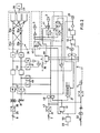
- the protection device is composed of various individual parts. It contains an electronic control unit 2, which monitors the machine or system and switches it off under certain conditions by acting on the control 1.
- this device includes a main pump 3, an auxiliary pump 4, two valves 5, 6, two pressure wave switches 7, 8 which are connected to one another in a manner to be shown and a number of so-called safety sockets 9 arranged in the area to be kept free, which form under this area , floating floor 10 are located.
- Each box 9 consists of a lower part and an upper part which is displaceable relative thereto. When stepping on the floor, the upper part of at least one can is pressed into the lower part and thereby causes pressure changes in a pneumatic line network, which consists of three independent parts 11, 12, 13.
- the main pump 3, the Safety boxes 9 and the first pressure wave switch 7 are arranged in series in the first section 11.
- This switch 7 contains a bubble-shaped membrane 14 in its interior. It is connected to the same membrane 15, which is arranged in the second pressure wave switch, the monitoring pressure wave switch 8, through the section 12 of the line network.
- the third section 13 connects the space between this membrane 15 and the housing of the pressure wave switch 8 with the auxiliary pump 4.
- the first branch line 16 begins at a point in the section 11, which is located between the main pump 3 and the boxes 9, and ends at the valve 5 belonging to the main pump 3.
- the branch line 17 branches from the section 12 at a point between the two Pressure wave switches 7,8 and ends next to the branch line 16 at the same point.
- the branch line 18 leads from a point in the section 13 between the monitoring pressure wave switch 8 and the auxiliary pump 4 to the valve 6 belonging to the latter.
- the two valves 5, 6 are solenoid valves; a rubber plate is attached to each of the cores immersed in the relevant electromagnet, which, when the electromagnet is excited, rests against the open ends of the branch lines 16, 17 (at valve 5) or the open end of branch line 18 (at valve 6) .
- Each of the two diaphragms 14, 15 contains two contact pieces 19, 20 which lie on top of one another when the pressure in the diaphragm in question drops for reasons to be shown.
- the main pump 3, the auxiliary pump 4 and the two valves 5, 6 are electrically connected to the control unit 2 and are controlled by them or transmit their respective operating states to the same.
- the device is put into operation by connecting the control unit 2 to the mains voltage, which can be done either directly or via the controller 1 of the machine or system.
- the control unit 2 shows on a display device 21 shown here only symbolically, e.g. a display board, this process, e.g. by lighting up a lamp "power on"
- a start button 22 is now pressed. It preferably acts on the controller 1, which forwards a signal via a line 23 to the control device 2 or to the display device 21, on which the corresponding signals light up. At a transition 23 'from control unit 2 to machine control 1, a contact is closed. The latter can now be controlled from control unit 2.
- the start button 22 triggers further pulses.
- the auxiliary pump 4 now carries out a function test in that, since it is a vacuum pump, it generates a vacuum surge in the section 13. This propagates into the monitoring pressure wave switch 8 and causes it there an inflation of the bubble-shaped membrane 15, which, because the valve 6 was still open until recently, had been supplied with air under atmospheric pressure via the branch line 18.
- the increase in volume of the diaphragm 15 causes the diaphragm 14 of the working pressure wave switch 7 to contract because the air flows out of it into the diaphragm 15, which has become larger, and the closed branch line 17 cannot compensate for this outflow.
- the membrane 14 finally becomes so narrow that its two contact pieces 19, 20 touch one another. This creates an electrical pulse that reaches control unit 2 via line 24. There its time of arrival is compared in a manner to be shown with a predetermined time interval; if this arrival of the pulse is within the specified interval, the function test has been positive.
- the control unit 2 now starts the main pump 3. This works with short bursts of vacuum at fixed intervals, for example every two seconds. Each vacuum surge propagates through the safety boxes 9 to the working pressure wave switch 7. Now exactly the opposite happens as before: now the membrane 14 is inflated and the membrane 15 in the monitoring pressure wave switch 8 extracts the air, which then contracts and thereby puts its contact pieces together. The resulting electrical impulse is transmitted via a line 25 into the control unit 2, where it is evaluated as the proper functioning of the organs 3, 9 and 7. The valves 5,6 are briefly opened until a new vacuum surge is triggered. As a result, the pressure in the branch lines 16-18, which could possibly have changed due to temperature fluctuations, can be reset to the initial value.
- the device is therefore largely operationally safe and immediately switches off the machine or system it is monitoring to all conceivable unusual operating states.
- the monitoring pressure wave switch 8 is shown at the top left of this figure. This has just received a pneumatic monitoring pulse.
- An electrical pulse triggered by the contraction of its membrane 14 and the consequent closure of its contact pieces 19, 20 (FIG. 1) passes through the line 25 initially in a pulse duration limiter 30. Here the pulse is limited to a duration of three milliseconds.
- This shortened pulse arrives in a transformer 31 with one input, but with two outputs. A pulse now appears on each of these.
- Both pulses pass through a gate 32 each and arrive at a capacitor 33, which acts as a time constant element. Due to the impulses arriving at exactly the same time and lasting for the same length, both capacitors are suddenly charged to a voltage, for example to 24 V, which then slowly degrades again.
- Each voltage pulse is passed via a buffer element 34 to an output relay group 35 consisting of four relays 35a-35d.
- Each of the first two relays 35a, 35b taking over the pulse is coupled to the two subsequent relays 35c, 35d; there is therefore a crosswise coupling which prevents impulses due to disturbances in individual components from reaching outputs 1 to controller 1 which should have been eliminated beforehand.
- the main pump 3 emits a vacuum surge into the line network 11, 12, 13 every two seconds, for example. Because this also causes the switch 8 to close regularly, an electrical pulse arrives at the time constant elements 33 at the same time intervals. In the meantime, they can discharge only slightly, so that the two relays 35a, 35b do not drop out. Only when the two parallel pulses are absent do the two time constant elements 33 continue to discharge to the value at which the relays mentioned drop out and thus initiate the shutdown of the connected machine. During normal unloading, however, a value is regularly undershot by a Threshold switch 37 is determined.
- This threshold value had been exceeded during the abrupt charging of the two time constant elements 33 mentioned above and had thereby caused a relay 38 dependent on the threshold value switch 37 to drop out, which led to the resetting of a multivibrator 39.
- the threshold value falls below again due to the slow decrease in the voltages at the time constant elements 33.
- the threshold switch 37 responds to it and the relay 38 is tightened again.
- an electrical pulse is given to a further time constant element 40 which is connected upstream of the main pump valve 5.
- the latter opens during the time determined by the time constant element 40, for example for about 150 msec, as a result of which the branch lines 16, 17 and thus the connected sections 11, 12 are vented, so that normal pressure prevails in these sections again. This is particularly important if, for example, a rise in pressure has taken place as a result of heating, which could mainly influence the switches 7, 8 which respond to negative pressure.
- the pulse on the main pump 3 sets the multivibrator 39 in a state of alarm preparation. However, the control pulse arriving via relay 38 resets it; the alarm stops.
- a delay circuit 42 is also put into operation with the pump pulse. Their delay time is somewhat shorter than the running time of the pneumatic monitoring pulse. After its time has elapsed, the circuit 42 opens the two gates 32 for a short time, for example for about 400 msec, so that the pulse from the monitoring switch 8 can pass through the gates 32 to the time constant elements 33 and on to the relay group 35.
- This delay circuit 42 is intended to prevent the monitoring pulse emanating from the main pump 3 from being passed directly to the monitoring switch 8 by bypassing the floor 10. The duration of this impulse would then be shorter; but then the electrical impulse triggered by it comes in front of the gates 32 at a time when these are still closed. The pulse is therefore not passed on, and relay group 35 switches control 1 off by falling.
- the pneumatic monitoring pulse arrives too late, too early or no longer at all for some reason, for example because of a defect or because the floor 10 has been occupied and the safety sockets 9 are thus closed. Because of the missing recharge pulse discharge the time constant elements 33 now continuously; their voltage initially falls below the threshold value of the threshold switch 37 and soon thereafter also that of the two relays 35a, 35b, so that the latter drop out. Because the bipolar relay 38 picks up when the threshold value is undershot, but can no longer drop, the multivibrator 39 is also no longer reset for the time being. Its pulse arrives at a time delay stage 43 which, due to the lack of a reset pulse, sets an alarm multivibrator 44 after its time, which is followed by an alarm device 45 including alarm clock generator 46.
- the multivibrator 44 mentioned initially only acts on the main pump 3 and puts it out of operation. This also means that the monitoring pulses fail, so that there is definitely a guarantee that the relays 35a, 35b must drop out. A defect or malfunction affects the safe side. If the protection device has worked properly before the malfunction, a reset signal is finally sent to the multivibrator 39 via the time delay stage 43, which is then still reset. This prevents an unnecessary alarm; it is sufficient that the connected machine or system is taken out of operation.
- the occupancy of the floor 10 and thus the blocking of the safety sockets 9, in addition to the non-transmission of the pneumatic monitoring pulse also means that the working pressure wave switch 7 receives a pressure surge as a result of the occupancy process.
- the working pressure wave switch 7 is set back to its normal position. However, it still receives no impulses because the main pump has been switched off. It must therefore be put back into operation first, which is effected by a pulse on the time constant element 40, which actuates the main pump valve 5 in order to produce the normal pressure in line 11. Then another pulse follows, this time on the main pump 3. This then resumes the monitoring cycle already described, and the relay group 35 switches the outputs ..36 on again. If the device is to be put into operation after it has been completely switched off, for example when starting work, the start button 22 is actuated first. As a result, the controller 1 of the machine or system is energized, which in turn now applies a direct voltage to the control unit 2.
- a reset circuit 50 serves as input, to which a multivibrator 51 connects, which is connected both to the display device 21 and to the circuit 48 already mentioned. If the voltage in the circuit 50 reaches a certain value, for example 20 V, the reset state is canceled. However, the onset of current flow is initially blocked by the multivibrator 51. To set this, the pressure wave switch 7, the pulse of which sets the multivibrator, must now be operated first. Now the discharge switches 49 controlled, which in turn now check the time constant elements 33 for absence of voltage or discharge them when voltage is still present, which can be the case, for example, after a brief interruption. In any case, it is checked whether the relays 35 are in the dropped state or, if necessary, must be immediately transferred to them.
- the multivibrator 39 remains set, as does the alarm multivibrator 44.
- the alarm elements 45, 46 and the display device 21 are now switched on. As mentioned, this alarm is only triggered when the floor 10 is switched on and is already occupied.
- the device is now switched on, but not yet ready for operation, because the relay group 35 is in the dropped state.
- the main pump valve 5 In order to take up the cyclical control functions, the main pump valve 5 must be started by an impulse via the time constant element 40. This impulse can now only come from the pressure wave switch 7, which is why it must be actuated, either by walking on the floor or then by actuating a subsequent one test switch 52 to be described later.
- the pulse of the switch 7 now not only puts the main pump 3 into operation, but also resets the multivibrator 51.
- the main pump 3 now begins to work, and the sub Pressure surges return via the pneumatic line network 11-13 to switch 7, which in turn gives the main pump the impulse to continue.
- the device is again in the state of continuous self-monitoring.
- the functionality of the device can also be checked by hand.
- the test switch 52 already mentioned is used for this purpose. It is opened briefly, which results in a pulse which acts on switching element 48 in exactly the same way as the pulse mentioned above when the voltage rises, thereby checking the dropped state of relay group 35 or possibly causing it. However, this pulse does not go through the multivibrator 51, and the main pump 3 thus remains out of operation. Therefore, the auxiliary pump 4 is started. It emits a short vacuum surge on the monitoring pressure wave switch 8, which now actuates the working pressure wave switch 7 via the interconnected diaphragm 14, 15 in the same way as the pressure wave triggered by walking on the floor 10, mentioned above. The working pressure wave switch 7 is thus actuated, and the other processes up to automatic self-monitoring take place in the same way as when the device was started up previously.
- the device not only monitors the connected machine or system or the danger zone, but also itself by regularly checking its own components for their functioning and, if one of them fails, the machine or is immediately switched off System initiates and this switching off and thus indirectly indicates the defect.
Applications Claiming Priority (2)
| Application Number | Priority Date | Filing Date | Title |
|---|---|---|---|
| CH245582 | 1982-04-22 | ||
| CH2455/82 | 1982-04-22 |
Publications (2)
| Publication Number | Publication Date |
|---|---|
| EP0092744A2 true EP0092744A2 (fr) | 1983-11-02 |
| EP0092744A3 EP0092744A3 (fr) | 1985-10-16 |
Family
ID=4234215
Family Applications (1)
| Application Number | Title | Priority Date | Filing Date |
|---|---|---|---|
| EP83103628A Withdrawn EP0092744A3 (fr) | 1982-04-22 | 1983-04-14 | Dispositif électropneumatique de protection d'une zone dangereuse d'une machine ou installation en service |
Country Status (1)
| Country | Link |
|---|---|
| EP (1) | EP0092744A3 (fr) |
Cited By (4)
| Publication number | Priority date | Publication date | Assignee | Title |
|---|---|---|---|---|
| GB2180029A (en) * | 1985-09-03 | 1987-03-18 | Coal Ind | Personnel detection and protection systems for use in underground mines |
| EP0228550A2 (fr) * | 1985-11-23 | 1987-07-15 | Wolfram Försterling | Méthode de surveillance électropneumatique d'objets mobiles et système de surveillance pour la mise en oeuvre de la méthode |
| DE3921641A1 (de) * | 1989-06-30 | 1991-01-24 | Hoermann Kg Antrieb Steuertec | Sicherungsgeraet fuer die schliesskante eines torblattes |
| EP1073077A2 (fr) * | 1999-07-24 | 2001-01-31 | Bircher AG | Méthode pour actionner un capteur de signaux tel qu'un élément de commutation |
Citations (4)
| Publication number | Priority date | Publication date | Assignee | Title |
|---|---|---|---|---|
| GB1468521A (en) * | 1974-04-03 | 1977-03-30 | Herga Electric | Control apparatus |
| CH610382A5 (en) * | 1976-04-09 | 1979-04-12 | Bircher Ag | Electropneumatic safety control device for an automatic door or gate operating system |
| DE3000138A1 (de) * | 1979-01-26 | 1980-08-07 | Bircher Ag | Elektropneumatische sicherheitssteuereinrichtung |
| GB1594577A (en) * | 1978-02-03 | 1981-07-30 | Herga Electric | Control apparatus |
-
1983
- 1983-04-14 EP EP83103628A patent/EP0092744A3/fr not_active Withdrawn
Patent Citations (4)
| Publication number | Priority date | Publication date | Assignee | Title |
|---|---|---|---|---|
| GB1468521A (en) * | 1974-04-03 | 1977-03-30 | Herga Electric | Control apparatus |
| CH610382A5 (en) * | 1976-04-09 | 1979-04-12 | Bircher Ag | Electropneumatic safety control device for an automatic door or gate operating system |
| GB1594577A (en) * | 1978-02-03 | 1981-07-30 | Herga Electric | Control apparatus |
| DE3000138A1 (de) * | 1979-01-26 | 1980-08-07 | Bircher Ag | Elektropneumatische sicherheitssteuereinrichtung |
Cited By (7)
| Publication number | Priority date | Publication date | Assignee | Title |
|---|---|---|---|---|
| GB2180029A (en) * | 1985-09-03 | 1987-03-18 | Coal Ind | Personnel detection and protection systems for use in underground mines |
| GB2180029B (en) * | 1985-09-03 | 1989-08-23 | Coal Ind | Personnel detection and protection systems for use in underground mines |
| EP0228550A2 (fr) * | 1985-11-23 | 1987-07-15 | Wolfram Försterling | Méthode de surveillance électropneumatique d'objets mobiles et système de surveillance pour la mise en oeuvre de la méthode |
| EP0228550A3 (fr) * | 1985-11-23 | 1987-10-28 | Wolfram Försterling | Méthode de surveillance électropneumatique d'objets mobiles et système de surveillance pour la mise en oeuvre de la méthode |
| DE3921641A1 (de) * | 1989-06-30 | 1991-01-24 | Hoermann Kg Antrieb Steuertec | Sicherungsgeraet fuer die schliesskante eines torblattes |
| EP1073077A2 (fr) * | 1999-07-24 | 2001-01-31 | Bircher AG | Méthode pour actionner un capteur de signaux tel qu'un élément de commutation |
| EP1073077A3 (fr) * | 1999-07-24 | 2002-07-24 | Bircher AG | Méthode pour actionner un capteur de signaux tel qu'un élément de commutation |
Also Published As
| Publication number | Publication date |
|---|---|
| EP0092744A3 (fr) | 1985-10-16 |
Similar Documents
| Publication | Publication Date | Title |
|---|---|---|
| WO2003085313A2 (fr) | Appareil de coupure, protegee contre les erreurs, d'un consommateur electrique, notamment dans les installations de production industrielle | |
| DE10118885C1 (de) | Vakuumerzeuger | |
| EP0092744A2 (fr) | Dispositif électropneumatique de protection d'une zone dangereuse d'une machine ou installation en service | |
| EP0064642B1 (fr) | Dispositif électrique de sécurité pour la commande d'une machine à imprimer | |
| WO2019086205A1 (fr) | Dispositif de surveillance de sécurité destiné à surveiller des états relatifs à la sécurité dans une installation de transport de personnes ainsi que procédé destiné à faire fonctionner ce dernier | |
| DE3103920C2 (de) | "Schaltungsanordnung zur Funktionsüberwachung eines elektrischen Fühlers" | |
| DE3537275C2 (fr) | ||
| DE112019006581T5 (de) | Solarstromerzeugungssystem | |
| DE3312768C2 (fr) | ||
| DE3000138A1 (de) | Elektropneumatische sicherheitssteuereinrichtung | |
| DE19941022A1 (de) | Steuergerät für wärmetechnische Anlagen | |
| DE1563836C3 (de) | Elektrische Energieverteilungsanlage mit mehreren in Reihe liegenden Schahgeräten | |
| EP0949735A2 (fr) | Procédé et circuit pour la surveillance de la sécurité d'un système d'alimentation à haute tension | |
| DE3725635C2 (fr) | ||
| EP0117461B1 (fr) | Dispositif de contrôle en particulier pour une machine, une porte, ou dispositifs similaires | |
| DE1605428C (de) | Schaltungsanordnung zum Prüfen von relaisüberwachten Signalstromkreisen, insbesondere Lichtsignalstromkreisen im Eisenbahnsicherungswesen, auf Fremdspannungseinfall | |
| CH639788A5 (en) | Safety device for prompt de-activation or switchover of an installation when a dangerous situation occurs | |
| DE729623C (de) | Einrichtung zum Schutz von Gleichstrom-Hochspannungskraftuebertragungsanlagen | |
| DE3022077C2 (fr) | ||
| DE2262973C3 (de) | Steuerschaltung für eine Alarmanlage | |
| DE976088C (de) | Schaltung fuer Vorsignale im Eisenbahnsicherungswesen | |
| EP3112966A1 (fr) | Commutateur de securite pour une installation electrique, en particulier pour une chaine de securite d'une installation d'ascenseur | |
| DE2818173B1 (de) | Anordnung zur elektrischen UEberwachung von Pressensicherheitsventilen | |
| DE1100676B (de) | Schaltungsanordnung in elektrischen Eisenbahnstellwerken mit einem akustischen Stoerungsmelder | |
| DE878368C (de) | Schalteinrichtung fuer das Eisenbahnsicherungswesen |
Legal Events
| Date | Code | Title | Description |
|---|---|---|---|
| PUAI | Public reference made under article 153(3) epc to a published international application that has entered the european phase |
Free format text: ORIGINAL CODE: 0009012 |
|
| AK | Designated contracting states |
Designated state(s): AT DE FR GB IT SE |
|
| PUAL | Search report despatched |
Free format text: ORIGINAL CODE: 0009013 |
|
| AK | Designated contracting states |
Designated state(s): AT DE FR GB IT SE |
|
| STAA | Information on the status of an ep patent application or granted ep patent |
Free format text: STATUS: THE APPLICATION IS DEEMED TO BE WITHDRAWN |
|
| 18D | Application deemed to be withdrawn |
Effective date: 19860618 |
|
| RIN1 | Information on inventor provided before grant (corrected) |
Inventor name: BAENTELI, WILLY Inventor name: DIETRICH, ROLF Inventor name: BOS, ISAAC |