EP0092744A2 - Electropneumatic device for the fuse protection of a danger area at a machine or installation in operation - Google Patents
Electropneumatic device for the fuse protection of a danger area at a machine or installation in operation Download PDFInfo
- Publication number
- EP0092744A2 EP0092744A2 EP83103628A EP83103628A EP0092744A2 EP 0092744 A2 EP0092744 A2 EP 0092744A2 EP 83103628 A EP83103628 A EP 83103628A EP 83103628 A EP83103628 A EP 83103628A EP 0092744 A2 EP0092744 A2 EP 0092744A2
- Authority
- EP
- European Patent Office
- Prior art keywords
- switch
- pressure wave
- pulse
- time constant
- pressure
- Prior art date
- Legal status (The legal status is an assumption and is not a legal conclusion. Google has not performed a legal analysis and makes no representation as to the accuracy of the status listed.)
- Withdrawn
Links
Images

Classifications
-
- F—MECHANICAL ENGINEERING; LIGHTING; HEATING; WEAPONS; BLASTING
- F16—ENGINEERING ELEMENTS AND UNITS; GENERAL MEASURES FOR PRODUCING AND MAINTAINING EFFECTIVE FUNCTIONING OF MACHINES OR INSTALLATIONS; THERMAL INSULATION IN GENERAL
- F16P—SAFETY DEVICES IN GENERAL; SAFETY DEVICES FOR PRESSES
- F16P3/00—Safety devices acting in conjunction with the control or operation of a machine; Control arrangements requiring the simultaneous use of two or more parts of the body
- F16P3/12—Safety devices acting in conjunction with the control or operation of a machine; Control arrangements requiring the simultaneous use of two or more parts of the body with means, e.g. feelers, which in case of the presence of a body part of a person in or near the danger zone influence the control or operation of the machine
Definitions
- the invention relates to an electropneumatic device for safeguarding a danger zone in a machine or system that is in operation, this danger zone being secured by a floor connected to a pneumatic line network, when it is entered or occupied, at least one pressure wave propagates to at least one first pressure wave switch, which then the machine or system is switched off by means of an electrical pulse.
- Devices of this type serve to prevent industrial accidents. First and foremost, it is thought of people who get too close to a working machine or another system in motion (e.g. a conveyor belt, a so-called industrial robot which transports machined workpieces from one machine to the next using a swivel movement, but also a closing factory gate) stop protecting from this machine or system.
- a working machine or another system in motion e.g. a conveyor belt, a so-called industrial robot which transports machined workpieces from one machine to the next using a swivel movement, but also a closing factory gate
- the device is also intended to prevent objects from being inadvertently placed in the area of such a system, which then hinder the movement, in particular a pivoting movement, and thereby lead to damage to the machine or system and thus to costly interruptions in operation.
- the invention therefore has the purpose of creating an electropneumatic device which not only continuously monitors the connected machine or system, but also itself and any fault, whether it occurs on the machine or system or on the device itself, immediately as is able to recognize and report such. I.
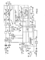
- the protection device is composed of various individual parts. It contains an electronic control unit 2, which monitors the machine or system and switches it off under certain conditions by acting on the control 1.
- this device includes a main pump 3, an auxiliary pump 4, two valves 5, 6, two pressure wave switches 7, 8 which are connected to one another in a manner to be shown and a number of so-called safety sockets 9 arranged in the area to be kept free, which form under this area , floating floor 10 are located.
- Each box 9 consists of a lower part and an upper part which is displaceable relative thereto. When stepping on the floor, the upper part of at least one can is pressed into the lower part and thereby causes pressure changes in a pneumatic line network, which consists of three independent parts 11, 12, 13.
- the main pump 3, the Safety boxes 9 and the first pressure wave switch 7 are arranged in series in the first section 11.
- This switch 7 contains a bubble-shaped membrane 14 in its interior. It is connected to the same membrane 15, which is arranged in the second pressure wave switch, the monitoring pressure wave switch 8, through the section 12 of the line network.
- the third section 13 connects the space between this membrane 15 and the housing of the pressure wave switch 8 with the auxiliary pump 4.
- the first branch line 16 begins at a point in the section 11, which is located between the main pump 3 and the boxes 9, and ends at the valve 5 belonging to the main pump 3.
- the branch line 17 branches from the section 12 at a point between the two Pressure wave switches 7,8 and ends next to the branch line 16 at the same point.
- the branch line 18 leads from a point in the section 13 between the monitoring pressure wave switch 8 and the auxiliary pump 4 to the valve 6 belonging to the latter.
- the two valves 5, 6 are solenoid valves; a rubber plate is attached to each of the cores immersed in the relevant electromagnet, which, when the electromagnet is excited, rests against the open ends of the branch lines 16, 17 (at valve 5) or the open end of branch line 18 (at valve 6) .
- Each of the two diaphragms 14, 15 contains two contact pieces 19, 20 which lie on top of one another when the pressure in the diaphragm in question drops for reasons to be shown.
- the main pump 3, the auxiliary pump 4 and the two valves 5, 6 are electrically connected to the control unit 2 and are controlled by them or transmit their respective operating states to the same.
- the device is put into operation by connecting the control unit 2 to the mains voltage, which can be done either directly or via the controller 1 of the machine or system.
- the control unit 2 shows on a display device 21 shown here only symbolically, e.g. a display board, this process, e.g. by lighting up a lamp "power on"
- a start button 22 is now pressed. It preferably acts on the controller 1, which forwards a signal via a line 23 to the control device 2 or to the display device 21, on which the corresponding signals light up. At a transition 23 'from control unit 2 to machine control 1, a contact is closed. The latter can now be controlled from control unit 2.
- the start button 22 triggers further pulses.
- the auxiliary pump 4 now carries out a function test in that, since it is a vacuum pump, it generates a vacuum surge in the section 13. This propagates into the monitoring pressure wave switch 8 and causes it there an inflation of the bubble-shaped membrane 15, which, because the valve 6 was still open until recently, had been supplied with air under atmospheric pressure via the branch line 18.
- the increase in volume of the diaphragm 15 causes the diaphragm 14 of the working pressure wave switch 7 to contract because the air flows out of it into the diaphragm 15, which has become larger, and the closed branch line 17 cannot compensate for this outflow.
- the membrane 14 finally becomes so narrow that its two contact pieces 19, 20 touch one another. This creates an electrical pulse that reaches control unit 2 via line 24. There its time of arrival is compared in a manner to be shown with a predetermined time interval; if this arrival of the pulse is within the specified interval, the function test has been positive.
- the control unit 2 now starts the main pump 3. This works with short bursts of vacuum at fixed intervals, for example every two seconds. Each vacuum surge propagates through the safety boxes 9 to the working pressure wave switch 7. Now exactly the opposite happens as before: now the membrane 14 is inflated and the membrane 15 in the monitoring pressure wave switch 8 extracts the air, which then contracts and thereby puts its contact pieces together. The resulting electrical impulse is transmitted via a line 25 into the control unit 2, where it is evaluated as the proper functioning of the organs 3, 9 and 7. The valves 5,6 are briefly opened until a new vacuum surge is triggered. As a result, the pressure in the branch lines 16-18, which could possibly have changed due to temperature fluctuations, can be reset to the initial value.
- the device is therefore largely operationally safe and immediately switches off the machine or system it is monitoring to all conceivable unusual operating states.
- the monitoring pressure wave switch 8 is shown at the top left of this figure. This has just received a pneumatic monitoring pulse.
- An electrical pulse triggered by the contraction of its membrane 14 and the consequent closure of its contact pieces 19, 20 (FIG. 1) passes through the line 25 initially in a pulse duration limiter 30. Here the pulse is limited to a duration of three milliseconds.
- This shortened pulse arrives in a transformer 31 with one input, but with two outputs. A pulse now appears on each of these.
- Both pulses pass through a gate 32 each and arrive at a capacitor 33, which acts as a time constant element. Due to the impulses arriving at exactly the same time and lasting for the same length, both capacitors are suddenly charged to a voltage, for example to 24 V, which then slowly degrades again.
- Each voltage pulse is passed via a buffer element 34 to an output relay group 35 consisting of four relays 35a-35d.
- Each of the first two relays 35a, 35b taking over the pulse is coupled to the two subsequent relays 35c, 35d; there is therefore a crosswise coupling which prevents impulses due to disturbances in individual components from reaching outputs 1 to controller 1 which should have been eliminated beforehand.
- the main pump 3 emits a vacuum surge into the line network 11, 12, 13 every two seconds, for example. Because this also causes the switch 8 to close regularly, an electrical pulse arrives at the time constant elements 33 at the same time intervals. In the meantime, they can discharge only slightly, so that the two relays 35a, 35b do not drop out. Only when the two parallel pulses are absent do the two time constant elements 33 continue to discharge to the value at which the relays mentioned drop out and thus initiate the shutdown of the connected machine. During normal unloading, however, a value is regularly undershot by a Threshold switch 37 is determined.
- This threshold value had been exceeded during the abrupt charging of the two time constant elements 33 mentioned above and had thereby caused a relay 38 dependent on the threshold value switch 37 to drop out, which led to the resetting of a multivibrator 39.
- the threshold value falls below again due to the slow decrease in the voltages at the time constant elements 33.
- the threshold switch 37 responds to it and the relay 38 is tightened again.
- an electrical pulse is given to a further time constant element 40 which is connected upstream of the main pump valve 5.
- the latter opens during the time determined by the time constant element 40, for example for about 150 msec, as a result of which the branch lines 16, 17 and thus the connected sections 11, 12 are vented, so that normal pressure prevails in these sections again. This is particularly important if, for example, a rise in pressure has taken place as a result of heating, which could mainly influence the switches 7, 8 which respond to negative pressure.
- the pulse on the main pump 3 sets the multivibrator 39 in a state of alarm preparation. However, the control pulse arriving via relay 38 resets it; the alarm stops.
- a delay circuit 42 is also put into operation with the pump pulse. Their delay time is somewhat shorter than the running time of the pneumatic monitoring pulse. After its time has elapsed, the circuit 42 opens the two gates 32 for a short time, for example for about 400 msec, so that the pulse from the monitoring switch 8 can pass through the gates 32 to the time constant elements 33 and on to the relay group 35.
- This delay circuit 42 is intended to prevent the monitoring pulse emanating from the main pump 3 from being passed directly to the monitoring switch 8 by bypassing the floor 10. The duration of this impulse would then be shorter; but then the electrical impulse triggered by it comes in front of the gates 32 at a time when these are still closed. The pulse is therefore not passed on, and relay group 35 switches control 1 off by falling.
- the pneumatic monitoring pulse arrives too late, too early or no longer at all for some reason, for example because of a defect or because the floor 10 has been occupied and the safety sockets 9 are thus closed. Because of the missing recharge pulse discharge the time constant elements 33 now continuously; their voltage initially falls below the threshold value of the threshold switch 37 and soon thereafter also that of the two relays 35a, 35b, so that the latter drop out. Because the bipolar relay 38 picks up when the threshold value is undershot, but can no longer drop, the multivibrator 39 is also no longer reset for the time being. Its pulse arrives at a time delay stage 43 which, due to the lack of a reset pulse, sets an alarm multivibrator 44 after its time, which is followed by an alarm device 45 including alarm clock generator 46.
- the multivibrator 44 mentioned initially only acts on the main pump 3 and puts it out of operation. This also means that the monitoring pulses fail, so that there is definitely a guarantee that the relays 35a, 35b must drop out. A defect or malfunction affects the safe side. If the protection device has worked properly before the malfunction, a reset signal is finally sent to the multivibrator 39 via the time delay stage 43, which is then still reset. This prevents an unnecessary alarm; it is sufficient that the connected machine or system is taken out of operation.
- the occupancy of the floor 10 and thus the blocking of the safety sockets 9, in addition to the non-transmission of the pneumatic monitoring pulse also means that the working pressure wave switch 7 receives a pressure surge as a result of the occupancy process.
- the working pressure wave switch 7 is set back to its normal position. However, it still receives no impulses because the main pump has been switched off. It must therefore be put back into operation first, which is effected by a pulse on the time constant element 40, which actuates the main pump valve 5 in order to produce the normal pressure in line 11. Then another pulse follows, this time on the main pump 3. This then resumes the monitoring cycle already described, and the relay group 35 switches the outputs ..36 on again. If the device is to be put into operation after it has been completely switched off, for example when starting work, the start button 22 is actuated first. As a result, the controller 1 of the machine or system is energized, which in turn now applies a direct voltage to the control unit 2.
- a reset circuit 50 serves as input, to which a multivibrator 51 connects, which is connected both to the display device 21 and to the circuit 48 already mentioned. If the voltage in the circuit 50 reaches a certain value, for example 20 V, the reset state is canceled. However, the onset of current flow is initially blocked by the multivibrator 51. To set this, the pressure wave switch 7, the pulse of which sets the multivibrator, must now be operated first. Now the discharge switches 49 controlled, which in turn now check the time constant elements 33 for absence of voltage or discharge them when voltage is still present, which can be the case, for example, after a brief interruption. In any case, it is checked whether the relays 35 are in the dropped state or, if necessary, must be immediately transferred to them.
- the multivibrator 39 remains set, as does the alarm multivibrator 44.
- the alarm elements 45, 46 and the display device 21 are now switched on. As mentioned, this alarm is only triggered when the floor 10 is switched on and is already occupied.
- the device is now switched on, but not yet ready for operation, because the relay group 35 is in the dropped state.
- the main pump valve 5 In order to take up the cyclical control functions, the main pump valve 5 must be started by an impulse via the time constant element 40. This impulse can now only come from the pressure wave switch 7, which is why it must be actuated, either by walking on the floor or then by actuating a subsequent one test switch 52 to be described later.
- the pulse of the switch 7 now not only puts the main pump 3 into operation, but also resets the multivibrator 51.
- the main pump 3 now begins to work, and the sub Pressure surges return via the pneumatic line network 11-13 to switch 7, which in turn gives the main pump the impulse to continue.
- the device is again in the state of continuous self-monitoring.
- the functionality of the device can also be checked by hand.
- the test switch 52 already mentioned is used for this purpose. It is opened briefly, which results in a pulse which acts on switching element 48 in exactly the same way as the pulse mentioned above when the voltage rises, thereby checking the dropped state of relay group 35 or possibly causing it. However, this pulse does not go through the multivibrator 51, and the main pump 3 thus remains out of operation. Therefore, the auxiliary pump 4 is started. It emits a short vacuum surge on the monitoring pressure wave switch 8, which now actuates the working pressure wave switch 7 via the interconnected diaphragm 14, 15 in the same way as the pressure wave triggered by walking on the floor 10, mentioned above. The working pressure wave switch 7 is thus actuated, and the other processes up to automatic self-monitoring take place in the same way as when the device was started up previously.
- the device not only monitors the connected machine or system or the danger zone, but also itself by regularly checking its own components for their functioning and, if one of them fails, the machine or is immediately switched off System initiates and this switching off and thus indirectly indicates the defect.
Abstract
Description
Die Erfindung betrifft eine elektropneumatische Einrichtung zur Absicherung eines Gefahrenbereiches bei einer in Betrieb stehenden Maschine oder Anlage, wobei dieser Gefahrenbereich durch einen an ein pneumatisches Leitungsnetz angeschlossenen Fussboden abgesichert ist, bei dessen Betretung oder Belegung sich mindestens eine Druckwelle zu wenigstens einem ersten Druckwellenschalter fortplanzt, der hierauf mittels eines elektrischen Impulses das Ausschalten der Maschine oder Anlage veranlasst.The invention relates to an electropneumatic device for safeguarding a danger zone in a machine or system that is in operation, this danger zone being secured by a floor connected to a pneumatic line network, when it is entered or occupied, at least one pressure wave propagates to at least one first pressure wave switch, which then the machine or system is switched off by means of an electrical pulse.
Einrichtungen dieser Art dienen zur Verhütung von Betriebsunfällen. In erster Linie wird daran gedacht, Personen, die sich zu nahe einer arbeitenden Maschine oder sonst einer in Bewegung stehenden Anlage (z.B. einem Förderband, einem sogenannten Industrieroboter welcherbearbeitete Werkstücke mittels einer Schwenkbewegung von einer Maschine zur nächsten befördert, aber auch ein sich schliessendes Fabriktor) aufhalten, vor dieser Maschine bzw. Anlage zu schützen. Die Einrichtung soll aber auch verhindern, dass aus Versehen Gegenstände im Bereich einer solchen Anlage abgestellt werden, welche dann die Bewegung, namentlich eine Schwenkbewegung, behindern und dabei zu Schäden an der Maschine bzw. Anlage und damit zu kostspieligen Betriebsunterbrechungen führen.Devices of this type serve to prevent industrial accidents. First and foremost, it is thought of people who get too close to a working machine or another system in motion (e.g. a conveyor belt, a so-called industrial robot which transports machined workpieces from one machine to the next using a swivel movement, but also a closing factory gate) stop protecting from this machine or system. However, the device is also intended to prevent objects from being inadvertently placed in the area of such a system, which then hinder the movement, in particular a pivoting movement, and thereby lead to damage to the machine or system and thus to costly interruptions in operation.
Einrichtungen dieser Art sind schon bekanntgeworden; als Beispiel seien diejenige nach den Schweizer Patentschriften 610 382 oder ...... (Gesuch 818/79) genannt. Solche Anlagen arbeiten sehr zuverlässig.Facilities of this kind have already become known; as examples are those according to the Swiss patent specifications 610 382 or ...... (application 818/79). Such systems work very reliably.
Nun sind aber in der letzten Zeit die Sicherheitsvorschriften wesentlich verschärft worden. Ausserdem ist zu bedenken, dass man sich auf das einwandfreie Funktionieren solcher Einrichtungen wegen der hohen Sicherheit, die sie bieten, restlos verlässt. Dies bedeutet aber, dass die Einrichtungen nicht nur das Auftreten einer Gefahr anzeigen müssen, sondern auch dann einen Alarm auslösen sollen, wenn an ihnen selber ein Defekt auftritt, wie immer dieser Defekt auch geartet sei. Diesen Ansprüchen vermochten allerdings die bisherigen Anlagen zwar weitgehend, aber nicht restlos zu genügen. Es bestand die Möglichkeit, dass bei bestimmten Defekten, deren Wahrscheinlichkeit jedoch äusserst gering war, die Einrichtung nicht in der Lage war, diesen Defekt zu erkennen und Alarm auszulösen.Now, however, the safety regulations have been tightened considerably. In addition, it should be borne in mind that one relies on the proper functioning of such facilities because of the high level of security they offer. However, this means that the facilities must not only indicate the occurrence of a hazard, but should also trigger an alarm if a defect occurs on them themselves, whatever the nature of this defect. However, previous systems were largely able to meet these requirements, but not completely. There was a possibility that for certain defects, the probability of which was extremely low, the facility would not be able to detect this defect and trigger the alarm.
Die Erfindung hat daher den Zweck, eine elektropneumatische Einrichtung zu schaffen, die nicht nur die angeschlossene Maschine oder Anlage, sondern auch sich selber dauernd überwacht und jede Störung, ob sie nun an der Maschine bzw. Anlage oder an der Einrichtung selber auftritt, sofort als solche zu erkennen und zu melden vermag. IThe invention therefore has the purpose of creating an electropneumatic device which not only continuously monitors the connected machine or system, but also itself and any fault, whether it occurs on the machine or system or on the device itself, immediately as is able to recognize and report such. I.
Eine solche Einrichtung der eingangs erwähnten Art ist durch die kennzeichnenden Merkmale des Anspruches 1 definiert.Such a device of the type mentioned is defined by the characterizing features of
Ein Ausführungsbeispiel der erfindungsgemässen Einrichtung wird anhand der beiliegenden Zeichnungen näher erläutert; es zeigen:
- Fig. 1 ein Schema des pneumatischen Teils der Einrichtung, und
- Fig. 2 ein Schema des elektronischen Teils, hauptsächlich ein Schema des Steuergerätes.
- Fig. 1 is a diagram of the pneumatic part of the device, and
- Fig. 2 is a diagram of the electronic part, mainly a diagram of the control unit.
Mit 1 ist eine Steuerung einer Maschine oder einer Anlage bezeichnet, die durch die erfindungsgemässe Einrichtung sofort ausser Betrieb gesetzt werden soll, wenn sich Personen innerhalb eines Gefahrenbereiches in der Nähe dieser Maschine bzw. Anlage aufhalten, in welchem sie entweder durch den Betrieb gefährdet sind oder umgekehrt diesen Betrieb durch ihre Anwesenheit stören. Die Abschaltung erfolgt auch, wenn sperrige Gegenstände in den genannten Bereich verbracht und dort abgelagert werden; wenn beispielsweise die Anlage ein sogenannter Industrieroboter ist, der an einer Fertigungsstrasse Schwenkbewegungen ausführt, dann muss ein Bereich abgegrenzt sein, der nicht durch andere Gegenstände derart belegt werden kann, dass die genannten Schwenkbewegungen behindert werden.1 with a control of a machine or a system is designated, which is to be put out of operation immediately by the device according to the invention if there are people within a danger zone in the vicinity of this machine or system, in which they are either endangered by the operation or conversely disrupt this operation by their presence. Switching off also takes place when bulky objects are brought into the area mentioned and deposited there; If, for example, the system is a so-called industrial robot that performs pivoting movements on a production line, then an area must be delimited that cannot be occupied by other objects in such a way that the mentioned pivoting movements are impeded.
Die erfindungsgemässe Absicherungseinrichtung setzt sich aus verschiedenen Einzelteilen zusammen. Sie enthält ein elektronisches Steuergerät 2, welches die Maschine bzw. Anlage überwacht und sie unter bestimmten Bedingungen durch Einwirkung auf die Steuerung 1 abschaltet. Im weiteren gehören zu dieser Einrichtung eine Hauptpumpe 3, eine Hilfspumpe 4, zwei Ventile 5,6, zwei miteinander in noch darzustellender Weise verbundene Druckwellenschalter 7,8 und eine Anzahl von im freizuhaltenden Bereich angeordnete sogenannte Sicherheitsdosen 9, die sich unter einem diesen Bereich bildenden, schwimmend angeordneten Fussboden 10 befinden. Jede Dose 9 besteht aus einem Unterteil und einem relativ dazu verschiebbaren Oberteil. Bei Betreten des Fussbodens wird der Oberteil mindestens einer Dose in den Unterteil gedrückt und bewirkt dadurch Druckänderungen in einem pneumatischen Leitungsnetz, welches aus drei voneinander unabhängigen Teilstücken 11,12,13 besteht. Die Hauptpumpe 3, die Sicherheitsdosen 9 und der erste Druckwellenschalter 7 sind in Serie im ersten Teilstück 11 angeordnet. Dieser Schalter 7 enthält in seinem Innern eine blasenförmige Membrane 14. Sie ist mit einer im zweiten Druckwellenschalter, dem Ueberwachungs-Druckwellenschalter 8,angeordneten gleichen Membrane 15 durch das Teilstück 12 des Leitungsnetzes verbunden. Das dritte Teilstück 13 verbindet den Zwischenraum zwischen dieser Membrane 15 und dem Gehäuse des Druckwellenschalters 8 mit der Hilfspumpe 4.The protection device according to the invention is composed of various individual parts. It contains an electronic control unit 2, which monitors the machine or system and switches it off under certain conditions by acting on the
Drei Zweigleitungen 16,17 und 18 zweigen von diesem Netz 11-13 ab. Die erste Zweigleitung 16 nimmt ihren Anfang an einem Punkt im Teilstück 11, der sich zwischen der Hauptpumpe 3 und den Dosen 9 befindet, und endet bei dem zur Hauptpumpe 3 gehörenden Ventil 5. Die Zweigleitung 17 zweigt vom Teilstück 12 an einem Punkt zwischen den beiden Druckwellenschaltern 7,8 ab und endet neben der Zweigleitung 16 an derselben Stelle. Die Zweigleitung 18 führt von einem Punkt im Teilstück 13 zwischen dem Ueberwachungs-Druckwellenschalter 8 und der Hilfspumpe 4 zu dem zu letzteren gehörenden Ventil 6. Die beiden Ventile 5,6 sind Solenoidventile; an jedem der in den betreffenden Elektromagneten eintauchenden Kerne ist ein Gummiteller angebracht, der sich in erregten Zustand des Elektromagneten auf die offenen Enden der Zweigleitungen 16,17 (beim Ventil 5) bzw. das offene Ende der Zweigleitung 18 (beim Ventil 6) abdichtend anlegt.Three
Jede der beiden Membrane 14,15 enthält zwei Kontaktstücke 19,20, die sich aufeinander legen, wenn der Druck in der betreffenden Membrane aus noch darzustellenden Gründen absinkt.Each of the two
Die Hauptpumpe 3, die Hilfspumpe 4 und die beiden Ventile 5,6 sind elektrisch an das Steuergerät 2 angeschlossen und werden von diesen aus angesteuert bzw. übermitteln ihre jeweiligen Betriebszustände an dasselbe.The
Nunmehr soll die Funktion des pneumatischen Teils der Einrichtung anhand von Fig. l erläutert werden.The function of the pneumatic part of the device will now be explained with reference to FIG.
Die Einrichtung wird in Betrieb genommen, indem das Steuergerät 2 an die Netzspannung angeschlossen wird, was entweder direkt oder über die Steuerung 1 der Maschine bzw. Anlage erfolgen kann. Das Steuergerät 2 zeigt auf einer hier nur symbolisch dargestellten Anzeigeeinrichtung 21, z.B. einer Anzeigetafel, diesen Vorgang an, z.B. durch Aufleuchten einer Lampe "Netz ein"The device is put into operation by connecting the control unit 2 to the mains voltage, which can be done either directly or via the
Nunmehr wird eine Starttaste 22 gedrückt. Sie wirkt vorzugsweise auf die Steuerung 1 ein, welche über eine Leitung 23 ein Signal an das Steuergerät 2 bzw. an die Anzeigevorrichtung 21 weiterleitet, an welcher die entsprechenden Signale aufleuchten. An einem Uebergang 23' vom Steuergerät 2 zur Maschinensteuerung 1 wird ein Kontakt geschlossen. Damit ist die letztere nunmehr vom Steuergerät 2 aus ansteuerbar.A start button 22 is now pressed. It preferably acts on the
Durch die Starttaste 22 werden noch weitere Impulse ausgelöst. Einer setzt die Hilfspumpe 4 in Betrieb, und ein weiterer schliesst die beiden Ventile 5,6, womit die Zweigleitungen 16-18 abgedichtet werden. Die Hilfspumpe 4 führt nun einen Funktionstest aus, indem sie, da sie eine Unterdruckpumpe ist, im Teilstück 13 einen Unterdruckstoss erzeugt. Dieser pfanzt sich in den Ueberwachungs-Druckwellenschalter 8 hinein fort und bewirkt dort ein Aufblähen der blasenförmigen Membrane 15, die, weil das Ventil 6 bis vor kurzem noch offen war, über die Zweigleitung 18 mit Luft unter Atmosphärendruck versorgt worden war. Die Volumenvergrösserung der Membrane 15 hat eine Zusammenziehung der Membrane 14 des Arbeitsdruckwellenschalters 7 zur Folge, weil die Luft aus ihr in die grösser gewordene Membrane 15 abströmt, und die geschlossene Zweigleitung 17 dieses Abströmen nicht ausgleichen kann. Die Membrane 14 wird schliesslich so schmal, dass ihre beiden Kontaktstücke 19,20 einander berühren. Dadurch entsteht ein elektrischer Impuls, der über eine Leitung 24 in das Steuergerät 2 gelangt. Dort wird sein zeitliches Eintreffen in noch darzustellender Weise mit einem vorgegebenen Zeitintervall verglichen; liegt dieses Eintreffen des Impulses innerhalb des genannten Intervalls, ist der Funktionstest positiv verlaufen.The start button 22 triggers further pulses. One puts the auxiliary pump 4 into operation, and another closes the two
Man ersieht daraus, dass beispielsweise bereits eine Störung an einem der beiden Ventile 5,6 dazu führen kann, dass kein Signal über die Leitung 24 abgegeben wird. Der Sog der Hilfspumpe 4 würde nämlich in diesem Störungsfalle über die dann offene Zweigleitung 18 ausgeglichen. Andererseits könnte auch die Zweigleitung 17 offen bleiben. In beiden Fällen würden die Membrane 14,15 druckausgeglichen und ihre Kontakte daher offen bleiben. Wenn aber kein Impuls über die Leitung 24 in das Steuergerät 2 gelangt, öffnet dieses nach Ablauf des erwähnten Zeitintervalls den Kontakt am Uebergang 23. Die Steuerung 1 und damit die angeschlossene Maschine oder Anlage werden ausgeschaltet.It can be seen from this that, for example, a fault on one of the two
Hat jedoch der Funktionstest das ordnungsgemässe Arbeiten aller Teile bestätigt, setzt das Steuergerät 2 nun die Hauptpumpe 3 in Betrieb. Diese arbeitet mit kurzen Unterdruckstössen in zeitlich festgelegten Abständen, also beispielsweise alle zwei Sekunden. Jeder Unterdruckstoss pflanzt sich über die Sicherheitsdosen 9 bis zum Arbeitsdruckwellenschalter 7 fort. Nun passiert genau das Umgekehrte wie vorher: jetzt wird die Membrane 14 aufgebläht und entzieht der Membrane 15 im Ueberwachungs-Druckwellenschalter 8 die Luft, die sich daraufhin zusammenzieht und dadurch ihre Kontaktstücke aneinanderlegt. Der daraus resultierende elektrische Impuls wird über eine Leitung 25 in das Steuergerät 2 übermittelt und dort als ordnungsgemässes Arbeiten der Organe 3,9 und 7 ausgewertet. Bis zur Auslösung eines neuen Unterdruckstosses werden kurz die Ventile 5,6 geöffnet. Dadurch kann sich der Druck in den Zweigleitungen 16-18, der eventuell wegen Temperaturschwankungen sich verändert haben könnte, jeweils wieder auf den Ausgangswert einstellen.However, if the function test has confirmed that all parts are working properly, the control unit 2 now starts the
Es sei nun angenommen, dass jemand kurz auf den Fussboden 10 tritt, diesen aber sofort wieder verlässt. Mindestens eine der Sicherheitsdosen 9 wird dadurch zusammengepresst, was im Teilstück 11 selbst dann einen Ueberdruckstoss auslöst, wenn die Hauptpumpe 3 gleichzeitig einen Unterdruckstoss bewirkt hat. Dieser Ueberdruckstoss oder der resultierende Druckstoss gelangt in das Gehäuse des Schalters 7 und drückt dort die Membrane 14 zusammen. Erneut resultiert daraus ein elektrischer Impuls auf der Leitung 24. Dieser liegt nun aber zeitlich anders als der Testimpuls, was vom Steuergerät 2 erkannt und durch sofortiges Abschalten der Steuerung 1 quittiert wird.It is now assumed that someone steps briefly on the
Wenn nun aber die Belastung einer der Sicherheitsdosen 9 bleibt, führt auch dies zum Ausschalten. Die Unterdruckstösse der Hauptpumpe 3 können sich nämlich nicht mehr über die nunmehr stets zusammengedrückte Sicherheitsdose 9 hinaus fortpflanzen. Die beiden Druckwellenschalter 7,8 erhalten keinen Ueber- oder Unterdruckstoss mehr. Ihre Membranen 14,15 bleiben daher ausser Betrieb, und nunmehr wird auch das Ausbleiben ihrer Signale vom Steuergerät 2 erkannt, welches auf dieses Fehlen mit Ausschalten der Steuerung 1 reagiert.However, if the load on one of the
Nun dürfte auch klar sein, dass eine Leckstelle in einem der Teilstücke 11,12,13 ebenfalls denselben Effekt bewirkt; die beiden Schalter 7,8 erhalten entweder gar keinen Unterdruckstoss mehr oder, falls einer doch noch eintrifft, wird er sofort ausgeglichen derart, dass die beiden Membrane 14,15 in ihrem Normalzustand verbleiben und keine elektrischen Impulse an das Steuergerät 2 abgeben.Now it should also be clear that a leak in one of the
Die Einrichtung ist also weitgehend betriebssicher und schaltet auf alle denkbaren unüblichen Betriebszustände sofort die von ihr überwachte Maschine oder Anlage ab.The device is therefore largely operationally safe and immediately switches off the machine or system it is monitoring to all conceivable unusual operating states.
Nunmehr soll anhand der Fig. 2 die Schaltung der Einrichtung, insbesondere diejenige des Steuergerätes 2, beschrieben werden.The circuit of the device, in particular that of the control unit 2, will now be described with reference to FIG. 2.
Links oben in dieser Figur ist der Ueberwachungs-Druckwellenschalter 8 dargestellt. Dieser hat soeben einen pneumatischen Ueberwachungsimpuls erhalten. Ein durch das Zusammenziehen seiner Membrane 14 und die dadurch bedingte Schliessung seiner Kontaktstücke 19,20 (Fig. l) ausgelöster elektrischer Impuls gelangt über die Leitung 25 vorerst in ein Impulsdauerbegrenzungsglied 30. Hier wird der Impuls auf die Dauer von drei Millisekunden begrenzt. Dieser verkürzte Impuls gelangt in einen Transformator 31 mit einem Eingang, jedoch mit zwei Ausgängen. An diesen erscheint nunmehr je ein Impuls. Beide Impulse passieren hierbei je ein Tor 32 und gelangen zu je einem als Zeitkonstantglied wirkenden Kondensator 33. Durch die zeitlich genau gleich eintreffenden und gleich lang dauernden Impulse werden beide Kondensatoren sprunghaft auf eine Spannung, beispielsweise auf 24V aufgeladen, die sich nachher wieder langsam abbaut. Jeder Spannungsimpuls wird über ein Pufferglied 34 auf eine Ausgangsrelaisgruppe 35, bestehend aus vier Relais 35a-35d, geleitet. Jedes der beiden ersten, den Impuls übernehmenden Relais 35a,35b ist mit den beiden nachfolgenden Relais 35c, 35d gekoppelt; es ist also eine kreuzweise Kopplung vorhanden, welche verhindert, dass infolge von Störungen in einzelnen Komponenten Impulse auf die Ausgänge 36 zur Steuerung 1 gelangen, die vorher hätten eliminiert werden sollen.The monitoring
Es wurde bei der Beschreibung des pneumatischen Teils erwähnt, dass die Hauptpumpe 3 beispielsweise alle zwei Sekunden einen Unterdruckstoss in das Leitungsnetz 11,12, 13 abgibt. Weil dadurch auch der Schalter 8 regelmässig schliesst, gelangt in gleichen zeitlichen Abständen je ein elektrischer Impuls auf die Zeitkonstantglieder 33. Diese können sich daher in der Zwischenzeit nur wenig entladen, sodass die beiden Relais 35a,35b nicht abfallen. Erst wenn die beiden Parallelimpulse ausbleiben, entladen sich die beiden Zeitkonstantglieder 33 weiter bis zu demjenigen Wert, an welchem die genannten Relais nunmehr abfallen und damit das Stillsetzen der angeschlossenen Maschine einleiten. Beim normalen Entladen wird jedoch regelmässig ein Wert unterschritten, der durch einen Schwellwertschalter 37 bestimmt ist. Dieser Schwellwert war beim weiter oben erwähnten sprunghaften Aufladen der beiden Zeitkonstantglieder 33 überschritten worden und hatte dadurch zum Abfallen eines vom Schwellwertschalter 37 abhängigen Relais 38 geführt, was zur Zurücksetzung eines Multivibrators 39 führte. Nunmehr wird jedoch wie erwähnt durch das langsame Absinken der Spannungen an den Zeitkonstantgliedern 33 der Schwellwert wieder unterschritten. Der Schwellwertschalter 37 spricht darauf an und das Relais 38 wird wieder angezogen. Dadurch wird ein elektrischer Impuls auf ein weiteres Zeitkonstantglied 40 gegeben, das dem Hauptpumpenventil 5 vorgeschaltet ist. Das letztere öffnet während der Zeit, die durch das Zeitkonstantglied 40 bestimmt ist, also für beispielsweise etwa 150 msec, wodurch die Zweigleitungen 16,17 und damit die angeschlossenen Teilstücke 11,12 entlüftet werden, sodass in diesen Teilstücken wieder Normaldruck herrscht. Dies ist vor allem dann von Bedeutung, wenn beispielsweise infolge von Erwärmung ein Druckanstieg stattgefunden hat, welcher hauptsächlich die auf Unterdruck ansprechenden Schalter 7,8 beeinflussen könnte.It was mentioned in the description of the pneumatic part that the
Sofort nach Ablauf der Laufzeit des Zeitkonstantgliedes 40 wird über ein weiteres Zeitkonstantglied, das Teil eines Pumpenschaltelementes 41 für die Hauptpumpe 3 bildet, ein Impuls auf dieses Element 41 gegeben. Dieses setzt nun die Hauptpumpe 3 für einen weiteren pneumatischen Ueberwachungsstoss in Betrieb, wie bereits weiter oben erwähnt wurde. Es folgt daraus, dass sich die ganze Einrichtung selber in Betrieb hält und somit selber überwacht. Sofern nirgends eine Störung auftritt, wiederholt sich dieser Ueberwachungszyklus ständig in gleichen Zeitintervallen, also vorzugsweise alle zwei Sekunden.Immediately after the running time of the time
Der Impuls auf die Hauptpumpe 3 setzt den Multivibrator 39 in einen Zustand der Alarmvorbereitung. Der über das Relais 38 eintreffende Kontrollimpuls setzt ihn jedoch wieder zurück; der Alarm unterbleibt.The pulse on the
Mit dem Pumpenimpuls wird auch eine Verzögerungsschaltung 42 in Betrieb genommen. Ihre Verzögerungszeit ist etwas kürzer als die Laufzeit des pneumatischen Ueberwachungsimpulses. Nach Ablauf ihrer Zeit öffnet die Schaltung 42 die beiden Tore 32 für eine kurze Zeit, beispielsweise für etwa 400 msec, damit der Impuls vom Ueberwachungsschalter 8 durch die Tore 32 hindurch zu den Zeitkonstantgliedern 33 und weiter zur Relaisgruppe 35 gelangen kann. Mit dieser Verzögerungsschaltung 42 soll vermieden werden, dass der von der Hauptpumpe 3 ausgehende Ueberwachungsimpuls unter Umgehung des Fussbodens 10 direkt auf den Ueberwachungsschalter 8 gegeben wird. Die Laufzeit dieses Impulses wäre dann kürzer; dann kommt aber der von ihm ausgelöste elektrische Impuls zu einer Zeit vor die Tore 32, bei welcher diese noch geschlossen sind. Der Impuls wird also nicht weitergeleitet, und die Relaisgruppe 35 schaltet durch Abfallen die Steuerung l aus.A
Im folgenden sollen nun einige weitere aussergewöhnliche Zustände betrachtet werden; einzelne wurden bereits angedeutet.In the following, some more exceptional conditions will be considered; some have already been hinted at.
Es sei vorerst angenommen, dass der pneumatische Ueberwachungsimpuls aus irgend einem Grunde zu spät, zu früh oder überhaupt nicht mehr eintrifft, beispielsweise wegen eines Defektes oder weil der Fussboden 10 belegt wurde und damit die Sicherheitsdosen 9 verschlossen sind. Wegen des fehlenden Wiederaufladeimpulses entladen sich die Zeitkonstantglieder 33 nunmehr ununterbrochen; ihre Spannung unterschreitet vorerst den Schwellwert des Schwellwertschalters 37 und bald darauf auch denjenigen der beiden Relais 35a, 35b, sodass die letzteren abfallen. Weil beim Unterschreiten des Schwellwertes das bipolare Relais 38 anzieht, nun aber nicht mehr abfallen kann, wird auch der Multivibrator 39 vorerst nicht mehr zurückgesetzt. Sein Impuls gelangt auf eine Zeitverzögerungsstufe 43, die wegen des Fehlens eines Rückstellimpulses nach Ablauf ihrer Zeit einen Alarmmultivibrator 44 setzt, dem eine Alarmvorrichtung 45 samt Alarmtaktgeber 46 nachgeschaltet sind. Der genannte Multivibrator 44 wirkt jedoch vorerst nur auf die Hauptpumpe 3 und setzt diese ausser Betrieb. Damit fallen auch die Ueberwachungsimpulse aus, sodass definitiv Gewähr dafür geboten ist, dass die Relais 35a,35b abfallen müssen. Ein Defekt oder eine Störung wirkt sich also auf die sichere Seite aus. Wenn die Absicherungseinrichtung vor der Störung einwandfrei gearbeitet hat, wird schliesslich ein Resetsignal über die Zeitverzögerungsstufe 43 auf den Multivibrator 39 gegeben, der dann doch noch zurückgesetzt wird. Damit wird ein unnötiger Alarm verhindert; es genügt, dass die angeschlossene Maschine oder Anlage ausser Betrieb gesetzt wird. Das Belegen des Fussbodens 10 und damit die Blockierung der Sicherheitsdosen 9 hat ausser der Nichtweiterleitung des pneumatischen Ueberwachungsimpulses auch zur Folge, dass der Arbeitsdruckwellenschalter 7 durch den Belegungsvorgang einen Druckstoss erhält. Dieser bewirkt die schon erwähnte Kompression der Membrane 14 und damit einen elektrischen Impuls auf die Leitung 24. Der letztere setzt über eine Entpreller- und Abfallverzögerungsstufe 47 ein Schaltelement 48 in Betrieb, welche zwei Entladeschalter 49 ansteuert. Diese entladen die beiden Zeitkonstantglieder 33 augenblicklich, die wegen der Blockierung der Sicherheitsdosen 9 nun auch nicht mehr aufgeladen werden können. Damit treten die weiter oben beschriebenen Folgen wie das Abfallen der Relaisgruppe 35 und das Ausschalten der Hauptpumpe 3 auf.It is initially assumed that the pneumatic monitoring pulse arrives too late, too early or no longer at all for some reason, for example because of a defect or because the
Wird der Fussboden 10 wieder freigegeben, wird zwar der Arbeitsdruckwellenschalter 7 wieder in seine Normalstellung zurückversetzt. Er erhält aber noch keine Impulse, denn die Hauptpumpe wurde ja abgeschaltet. Sie muss daher zuerst wieder in Betrieb genommen werden, was durch einen Impuls auf das Zeitkonstantglied 40 erfolgt, der das Hauptpumpenventil 5 zwecks Herstellung des Normaldruckes in der Leitung 11 betätigt. Dann folgt ein weiterer Impuls, diesmal auf die Hauptpumpe 3. Diese nimmt dann den schon beschriebenen Ueberwachungszyklus wieder auf, und die Relaisgruppe 35 schaltet die Ausgänge ..36 wieder ein. Soll die Einrichtung, nachdem sie völlig abgeschaltet war, also beispielsweise bei Arbeitsbeginn in Betrieb genommen werden, wird zuerst die Starttaste 22 betätigt. Dadurch wird die Steuerung 1 der Maschine oder Anlage unter Spannung gesetzt, die nun ihrerseits am Steuergerät2 eine Gleichspannung anlegt. Als Eingang dient eine Resetschaltung 50, an welche sich ein Multivibrator 51 anschliesst, der sowohl mit der Anzeigevorrichtung 21 als auch mit der schon erwähnten Schaltung 48 in Verbindung steht. Erreicht die Spannung in der Schaltung 50 einen bestimmten Wert, beispielsweise 20V, wird der Resetzustand aufgehoben. Der einsetzende Stromfluss wird jedoch vorerst vom Multivibrator 51 blockiert. Um diesen zu setzen, muss nun zuerst der Druckwellenschalter 7 betätigt werden, dessen Impuls den Multivibrator setzt. Nunmehr werden auch die Entladeschalter 49 angesteuert, welche nun ihrerseits die Zeitkonstantglieder 33 auf Spannungsfreiheit prüfen oder sie entladen, wenn noch Spannung vorhanden ist, was beispielsweise nach einem kurzen Unterbruch der Fall sein kann. Auf alle Fälle wird dadurch kontrolliert, ob sich die Relais 35 im abgefallenen Zustand befinden oder gegebenenfalls sofort in diesen überführt werden müssen.If the
Ist nun aber beim Einschalten der Absicherungseinrichtung der Fussboden 10 bereits belegt, kann der erste Ueberwachungsimpuls der Hauptpumpe 3 nicht bis zum Druckwellenschalter 7 gelangen. Der Multivibrator 39 bleibt gesetzt, ebenso der Alarmmultivibrator 44. Dadurch werden nun die Alarmorgane 45,46 und die Anzeigevorrichtung 21 eingeschaltet. Wie erwähnt, wird dieser Alarm aber nur beim Einschalten und bereits belegtem Fussboden 10 ausgelöst.However, if the
Nunmehr sei jedoch wieder angenommen, dass der Fussboden 10 frei sei.However, it is now assumed that the
Die Einrichtung ist nunmehr zwar eingeschaltet, aber noch nicht betriebsbereit, weil die Relaisgruppe 35 sich im abgefallenen Zustand befindet. Um die zyklischen Konstrollfunktionen aufzunehmen, muss das Hauptpumpenventil 5 gestartet werden und zwar durch einen Impuls über das Zeitkonstantglied 40. Dieser Impuls kann nun aber nur vom Druckwellenschalter 7 kommen, weshalb dieser betätigt werden muss, entweder durch Begehen des Fussbodens oder dann durch Betätigung eines nachfolgend noch zu beschreibenden Prüfschalters 52. Der Impuls des Schalters 7 nimmt nun nicht nur die Hauptpumpe 3 in Betrieb, sondern setzt auch den Multivibrator 51 zurück. Die Hauptpumpe 3 beginnt nun zu arbeiten, und die Unterdruckstösse gelangen via das pneumatische Leitungsnetz 11-13 wieder zurück zum Schalter 7,der jeweils wieder der Hauptpumpe dem Impuls zum Weitermachen gibt. Damit befindet sich die Einrichtung wieder im Zustand der dauernden Selbstüberwachung.The device is now switched on, but not yet ready for operation, because the
Die Einrichtung kann auch von Hand auf ihre Funktionsfähigkeit geprüft werden. Hierzu dient der schon erwähnte Prüfschalter 52. Er wird kurz geöffnet, was einen Impuls zur Folge hat, der genau gleich wie der vorhin erwähnte Impuls beim Spannungsanstieg auf das Schaltelement 48 wirkt und dadurch den abgefallenen Zustand der Relaisgruppe 35 nachprüft oder ihn gegebenenfalls herbeiführt. Dieser Impuls geht aber nicht über den Multivibrator 51, und damit bleibt die Hauptpumpe 3 ausser Betrieb. Daher wird die Hilfspumpe 4 in Betrieb gesetzt. Sie gibt einen kurzen Unterdruckstoss auf den Ueberwachungs-Druckwellenschalter 8 ab, der nun den Arbeitsdruckwellenschalter 7 über die miteinander verbundenen Membrane 14,15 in gleicher Weise betätigt wie die weiter oben erwähnte, durch die Begehung des Fussbodens 10 ausgelöste Druckwelle. Der Arbeitsdruckwellenschalter 7 ist damit betätigt, und die übrigen Vorgänge bis zur automatischen Selbstüberwachung spielen sich gleich ab wie bei der vorhin erwähnten Inbetriebnahme der Einrichtung.The functionality of the device can also be checked by hand. The
Wie aus den vorliegenden Ausführungen somit hervorgeht, überwacht die Einrichtung nicht nur die angeschlossene Maschine oder Anlage bzw. den Gefahrenbereich, sondern auch sich selber, indem sie regelmässig ihre eigenen Komponenten auf deren Funktionieren hin nachprüft und bei Ausfall eines derselben sofort die Ausschaltung der Maschine oder Anlage einleitet und dieses Ausschalten und damit indirekt auch den Defekt anzeigt.As can be seen from the present explanations, the device not only monitors the connected machine or system or the danger zone, but also itself by regularly checking its own components for their functioning and, if one of them fails, the machine or is immediately switched off System initiates and this switching off and thus indirectly indicates the defect.
Claims (14)
Applications Claiming Priority (2)
| Application Number | Priority Date | Filing Date | Title |
|---|---|---|---|
| CH245582 | 1982-04-22 | ||
| CH2455/82 | 1982-04-22 |
Publications (2)
| Publication Number | Publication Date |
|---|---|
| EP0092744A2 true EP0092744A2 (en) | 1983-11-02 |
| EP0092744A3 EP0092744A3 (en) | 1985-10-16 |
Family
ID=4234215
Family Applications (1)
| Application Number | Title | Priority Date | Filing Date |
|---|---|---|---|
| EP83103628A Withdrawn EP0092744A3 (en) | 1982-04-22 | 1983-04-14 | Electropneumatic device for the fuse protection of a danger area at a machine or installation in operation |
Country Status (1)
| Country | Link |
|---|---|
| EP (1) | EP0092744A3 (en) |
Cited By (4)
| Publication number | Priority date | Publication date | Assignee | Title |
|---|---|---|---|---|
| GB2180029A (en) * | 1985-09-03 | 1987-03-18 | Coal Ind | Personnel detection and protection systems for use in underground mines |
| EP0228550A2 (en) * | 1985-11-23 | 1987-07-15 | Wolfram Försterling | Method for electropneumatically controlling moving items, and control system for carrying out the method |
| DE3921641A1 (en) * | 1989-06-30 | 1991-01-24 | Hoermann Kg Antrieb Steuertec | SECURING DEVICE FOR THE CLOSING EDGE OF A DOOR LEAF |
| EP1073077A2 (en) * | 1999-07-24 | 2001-01-31 | Bircher AG | Method of operating a signal sensor like a switch element |
Citations (4)
| Publication number | Priority date | Publication date | Assignee | Title |
|---|---|---|---|---|
| GB1468521A (en) * | 1974-04-03 | 1977-03-30 | Herga Electric | Control apparatus |
| CH610382A5 (en) * | 1976-04-09 | 1979-04-12 | Bircher Ag | Electropneumatic safety control device for an automatic door or gate operating system |
| DE3000138A1 (en) * | 1979-01-26 | 1980-08-07 | Bircher Ag | ELECTROPNEUMATIC SAFETY CONTROL DEVICE |
| GB1594577A (en) * | 1978-02-03 | 1981-07-30 | Herga Electric | Control apparatus |
-
1983
- 1983-04-14 EP EP83103628A patent/EP0092744A3/en not_active Withdrawn
Patent Citations (4)
| Publication number | Priority date | Publication date | Assignee | Title |
|---|---|---|---|---|
| GB1468521A (en) * | 1974-04-03 | 1977-03-30 | Herga Electric | Control apparatus |
| CH610382A5 (en) * | 1976-04-09 | 1979-04-12 | Bircher Ag | Electropneumatic safety control device for an automatic door or gate operating system |
| GB1594577A (en) * | 1978-02-03 | 1981-07-30 | Herga Electric | Control apparatus |
| DE3000138A1 (en) * | 1979-01-26 | 1980-08-07 | Bircher Ag | ELECTROPNEUMATIC SAFETY CONTROL DEVICE |
Cited By (7)
| Publication number | Priority date | Publication date | Assignee | Title |
|---|---|---|---|---|
| GB2180029A (en) * | 1985-09-03 | 1987-03-18 | Coal Ind | Personnel detection and protection systems for use in underground mines |
| GB2180029B (en) * | 1985-09-03 | 1989-08-23 | Coal Ind | Personnel detection and protection systems for use in underground mines |
| EP0228550A2 (en) * | 1985-11-23 | 1987-07-15 | Wolfram Försterling | Method for electropneumatically controlling moving items, and control system for carrying out the method |
| EP0228550A3 (en) * | 1985-11-23 | 1987-10-28 | Wolfram Försterling | Method for electropneumatically controlling moving items, and control system for carrying out the method |
| DE3921641A1 (en) * | 1989-06-30 | 1991-01-24 | Hoermann Kg Antrieb Steuertec | SECURING DEVICE FOR THE CLOSING EDGE OF A DOOR LEAF |
| EP1073077A2 (en) * | 1999-07-24 | 2001-01-31 | Bircher AG | Method of operating a signal sensor like a switch element |
| EP1073077A3 (en) * | 1999-07-24 | 2002-07-24 | Bircher AG | Method of operating a signal sensor like a switch element |
Also Published As
| Publication number | Publication date |
|---|---|
| EP0092744A3 (en) | 1985-10-16 |
Similar Documents
| Publication | Publication Date | Title |
|---|---|---|
| WO2003085313A2 (en) | Device for the error-proof switching off of an electric consumer, particularly in industrial production plants | |
| DE10118885C1 (en) | vacuum generator | |
| EP0092744A2 (en) | Electropneumatic device for the fuse protection of a danger area at a machine or installation in operation | |
| EP0064642B1 (en) | Electric safety device for the control of a printing machine | |
| DE102010047220A1 (en) | Method for operating a voice announcement system | |
| WO2019086205A1 (en) | Safety monitoring device for monitoring safety-relevant states in a person-transporting system, and method for operating same | |
| DE3537275C2 (en) | ||
| DE112019006581T5 (en) | Solar power generation system | |
| DE3312768C2 (en) | ||
| DE3000138A1 (en) | ELECTROPNEUMATIC SAFETY CONTROL DEVICE | |
| DE19941022A1 (en) | Control unit for thermal systems | |
| DE1563836C3 (en) | Electrical power distribution system with several shah devices in series | |
| EP0949735A2 (en) | Method and circuit arrangement for safety control of a high voltage supply system | |
| DE3725635C2 (en) | ||
| DE2526539C3 (en) | Coupling link for mining machines in underground mining, in particular for roller cutting machines | |
| EP0117461B1 (en) | Control device, particularly for controlling a machine, a door or the like | |
| DE1605428C (en) | Circuit arrangement for testing relay-monitored signal circuits, in particular light signal circuits in railway safety systems, for external voltage | |
| CH639788A5 (en) | Safety device for prompt de-activation or switchover of an installation when a dangerous situation occurs | |
| DE3022077C2 (en) | ||
| DE2262973C3 (en) | Control circuit for an alarm system | |
| DE976088C (en) | Circuit for advance signals in railway security | |
| EP3112966A1 (en) | Safety switch for an electrical installation, in particular for a safety chain of a lift assembly | |
| DE2818173B1 (en) | Arrangement for electrical monitoring of press safety valves | |
| DE608789C (en) | Device for the automatic starting of synchronous machines, especially synchronous motors | |
| DE1100676B (en) | Circuit arrangement in electrical railway signal boxes with an acoustic fault alarm |
Legal Events
| Date | Code | Title | Description |
|---|---|---|---|
| PUAI | Public reference made under article 153(3) epc to a published international application that has entered the european phase |
Free format text: ORIGINAL CODE: 0009012 |
|
| AK | Designated contracting states |
Designated state(s): AT DE FR GB IT SE |
|
| PUAL | Search report despatched |
Free format text: ORIGINAL CODE: 0009013 |
|
| AK | Designated contracting states |
Designated state(s): AT DE FR GB IT SE |
|
| STAA | Information on the status of an ep patent application or granted ep patent |
Free format text: STATUS: THE APPLICATION IS DEEMED TO BE WITHDRAWN |
|
| 18D | Application deemed to be withdrawn |
Effective date: 19860618 |
|
| RIN1 | Information on inventor provided before grant (corrected) |
Inventor name: BAENTELI, WILLY Inventor name: DIETRICH, ROLF Inventor name: BOS, ISAAC |