EP0091686A2 - Dispositif semi-conducteur ayant une région diffusée à longueur réduite et procédé pour la fabrication de la région - Google Patents
Dispositif semi-conducteur ayant une région diffusée à longueur réduite et procédé pour la fabrication de la région Download PDFInfo
- Publication number
- EP0091686A2 EP0091686A2 EP83103501A EP83103501A EP0091686A2 EP 0091686 A2 EP0091686 A2 EP 0091686A2 EP 83103501 A EP83103501 A EP 83103501A EP 83103501 A EP83103501 A EP 83103501A EP 0091686 A2 EP0091686 A2 EP 0091686A2
- Authority
- EP
- European Patent Office
- Prior art keywords
- region
- invention according
- mosfet
- source
- type
- Prior art date
- Legal status (The legal status is an assumption and is not a legal conclusion. Google has not performed a legal analysis and makes no representation as to the accuracy of the status listed.)
- Granted
Links
- 239000004065 semiconductor Substances 0.000 title claims abstract description 37
- 238000004519 manufacturing process Methods 0.000 title claims abstract description 15
- 238000009792 diffusion process Methods 0.000 claims abstract description 21
- 239000002019 doping agent Substances 0.000 claims description 16
- 239000000758 substrate Substances 0.000 claims description 13
- 239000011819 refractory material Substances 0.000 claims description 12
- 229910052710 silicon Inorganic materials 0.000 claims description 11
- 239000010703 silicon Substances 0.000 claims description 11
- 230000001419 dependent effect Effects 0.000 claims description 7
- 238000005530 etching Methods 0.000 claims description 7
- 230000004888 barrier function Effects 0.000 claims description 6
- 239000013078 crystal Substances 0.000 claims description 4
- 230000000149 penetrating effect Effects 0.000 claims 1
- 230000003071 parasitic effect Effects 0.000 abstract description 16
- 238000000034 method Methods 0.000 abstract description 13
- 238000001465 metallisation Methods 0.000 description 10
- XUIMIQQOPSSXEZ-UHFFFAOYSA-N Silicon Chemical compound [Si] XUIMIQQOPSSXEZ-UHFFFAOYSA-N 0.000 description 9
- 229910021420 polycrystalline silicon Inorganic materials 0.000 description 7
- 229920005591 polysilicon Polymers 0.000 description 7
- KWYUFKZDYYNOTN-UHFFFAOYSA-M Potassium hydroxide Chemical compound [OH-].[K+] KWYUFKZDYYNOTN-UHFFFAOYSA-M 0.000 description 6
- VYPSYNLAJGMNEJ-UHFFFAOYSA-N Silicium dioxide Chemical compound O=[Si]=O VYPSYNLAJGMNEJ-UHFFFAOYSA-N 0.000 description 6
- 230000004048 modification Effects 0.000 description 6
- 238000012986 modification Methods 0.000 description 6
- 239000000463 material Substances 0.000 description 5
- 238000010276 construction Methods 0.000 description 3
- 150000002500 ions Chemical class 0.000 description 3
- 238000000206 photolithography Methods 0.000 description 3
- 239000000377 silicon dioxide Substances 0.000 description 3
- 235000012239 silicon dioxide Nutrition 0.000 description 3
- 238000006467 substitution reaction Methods 0.000 description 3
- KFZMGEQAYNKOFK-UHFFFAOYSA-N Isopropanol Chemical compound CC(C)O KFZMGEQAYNKOFK-UHFFFAOYSA-N 0.000 description 2
- 238000010420 art technique Methods 0.000 description 2
- QVGXLLKOCUKJST-UHFFFAOYSA-N atomic oxygen Chemical compound [O] QVGXLLKOCUKJST-UHFFFAOYSA-N 0.000 description 2
- 230000000903 blocking effect Effects 0.000 description 2
- TWNQGVIAIRXVLR-UHFFFAOYSA-N oxo(oxoalumanyloxy)alumane Chemical compound O=[Al]O[Al]=O TWNQGVIAIRXVLR-UHFFFAOYSA-N 0.000 description 2
- 229910052760 oxygen Inorganic materials 0.000 description 2
- 239000001301 oxygen Substances 0.000 description 2
- 238000005549 size reduction Methods 0.000 description 2
- ZOXJGFHDIHLPTG-UHFFFAOYSA-N Boron Chemical compound [B] ZOXJGFHDIHLPTG-UHFFFAOYSA-N 0.000 description 1
- OAICVXFJPJFONN-UHFFFAOYSA-N Phosphorus Chemical compound [P] OAICVXFJPJFONN-UHFFFAOYSA-N 0.000 description 1
- 230000002411 adverse Effects 0.000 description 1
- YXTPWUNVHCYOSP-UHFFFAOYSA-N bis($l^{2}-silanylidene)molybdenum Chemical compound [Si]=[Mo]=[Si] YXTPWUNVHCYOSP-UHFFFAOYSA-N 0.000 description 1
- 229910052796 boron Inorganic materials 0.000 description 1
- 230000000295 complement effect Effects 0.000 description 1
- 238000007796 conventional method Methods 0.000 description 1
- 230000006378 damage Effects 0.000 description 1
- 230000000694 effects Effects 0.000 description 1
- 230000005669 field effect Effects 0.000 description 1
- 239000011810 insulating material Substances 0.000 description 1
- 230000007246 mechanism Effects 0.000 description 1
- 239000000203 mixture Substances 0.000 description 1
- 229910021344 molybdenum silicide Inorganic materials 0.000 description 1
- 230000001590 oxidative effect Effects 0.000 description 1
- 229910052698 phosphorus Inorganic materials 0.000 description 1
- 239000011574 phosphorus Substances 0.000 description 1
- 238000001020 plasma etching Methods 0.000 description 1
- 230000000063 preceeding effect Effects 0.000 description 1
- 230000008569 process Effects 0.000 description 1
- WQJQOUPTWCFRMM-UHFFFAOYSA-N tungsten disilicide Chemical compound [Si]#[W]#[Si] WQJQOUPTWCFRMM-UHFFFAOYSA-N 0.000 description 1
- 229910021342 tungsten silicide Inorganic materials 0.000 description 1
Images


Classifications
-
- H—ELECTRICITY
- H01—ELECTRIC ELEMENTS
- H01L—SEMICONDUCTOR DEVICES NOT COVERED BY CLASS H10
- H01L29/00—Semiconductor devices adapted for rectifying, amplifying, oscillating or switching, or capacitors or resistors with at least one potential-jump barrier or surface barrier, e.g. PN junction depletion layer or carrier concentration layer; Details of semiconductor bodies or of electrodes thereof ; Multistep manufacturing processes therefor
- H01L29/66—Types of semiconductor device ; Multistep manufacturing processes therefor
- H01L29/68—Types of semiconductor device ; Multistep manufacturing processes therefor controllable by only the electric current supplied, or only the electric potential applied, to an electrode which does not carry the current to be rectified, amplified or switched
- H01L29/76—Unipolar devices, e.g. field effect transistors
- H01L29/772—Field effect transistors
- H01L29/78—Field effect transistors with field effect produced by an insulated gate
- H01L29/7801—DMOS transistors, i.e. MISFETs with a channel accommodating body or base region adjoining a drain drift region
- H01L29/7802—Vertical DMOS transistors, i.e. VDMOS transistors
-
- H—ELECTRICITY
- H01—ELECTRIC ELEMENTS
- H01L—SEMICONDUCTOR DEVICES NOT COVERED BY CLASS H10
- H01L21/00—Processes or apparatus adapted for the manufacture or treatment of semiconductor or solid state devices or of parts thereof
- H01L21/02—Manufacture or treatment of semiconductor devices or of parts thereof
- H01L21/04—Manufacture or treatment of semiconductor devices or of parts thereof the devices having at least one potential-jump barrier or surface barrier, e.g. PN junction, depletion layer or carrier concentration layer
- H01L21/18—Manufacture or treatment of semiconductor devices or of parts thereof the devices having at least one potential-jump barrier or surface barrier, e.g. PN junction, depletion layer or carrier concentration layer the devices having semiconductor bodies comprising elements of Group IV of the Periodic System or AIIIBV compounds with or without impurities, e.g. doping materials
- H01L21/30—Treatment of semiconductor bodies using processes or apparatus not provided for in groups H01L21/20 - H01L21/26
- H01L21/302—Treatment of semiconductor bodies using processes or apparatus not provided for in groups H01L21/20 - H01L21/26 to change their surface-physical characteristics or shape, e.g. etching, polishing, cutting
- H01L21/306—Chemical or electrical treatment, e.g. electrolytic etching
- H01L21/30604—Chemical etching
- H01L21/30608—Anisotropic liquid etching
-
- H—ELECTRICITY
- H01—ELECTRIC ELEMENTS
- H01L—SEMICONDUCTOR DEVICES NOT COVERED BY CLASS H10
- H01L21/00—Processes or apparatus adapted for the manufacture or treatment of semiconductor or solid state devices or of parts thereof
- H01L21/02—Manufacture or treatment of semiconductor devices or of parts thereof
- H01L21/04—Manufacture or treatment of semiconductor devices or of parts thereof the devices having at least one potential-jump barrier or surface barrier, e.g. PN junction, depletion layer or carrier concentration layer
- H01L21/18—Manufacture or treatment of semiconductor devices or of parts thereof the devices having at least one potential-jump barrier or surface barrier, e.g. PN junction, depletion layer or carrier concentration layer the devices having semiconductor bodies comprising elements of Group IV of the Periodic System or AIIIBV compounds with or without impurities, e.g. doping materials
- H01L21/30—Treatment of semiconductor bodies using processes or apparatus not provided for in groups H01L21/20 - H01L21/26
- H01L21/302—Treatment of semiconductor bodies using processes or apparatus not provided for in groups H01L21/20 - H01L21/26 to change their surface-physical characteristics or shape, e.g. etching, polishing, cutting
- H01L21/306—Chemical or electrical treatment, e.g. electrolytic etching
- H01L21/308—Chemical or electrical treatment, e.g. electrolytic etching using masks
-
- H—ELECTRICITY
- H01—ELECTRIC ELEMENTS
- H01L—SEMICONDUCTOR DEVICES NOT COVERED BY CLASS H10
- H01L29/00—Semiconductor devices adapted for rectifying, amplifying, oscillating or switching, or capacitors or resistors with at least one potential-jump barrier or surface barrier, e.g. PN junction depletion layer or carrier concentration layer; Details of semiconductor bodies or of electrodes thereof ; Multistep manufacturing processes therefor
- H01L29/02—Semiconductor bodies ; Multistep manufacturing processes therefor
- H01L29/06—Semiconductor bodies ; Multistep manufacturing processes therefor characterised by their shape; characterised by the shapes, relative sizes, or dispositions of the semiconductor regions ; characterised by the concentration or distribution of impurities within semiconductor regions
- H01L29/10—Semiconductor bodies ; Multistep manufacturing processes therefor characterised by their shape; characterised by the shapes, relative sizes, or dispositions of the semiconductor regions ; characterised by the concentration or distribution of impurities within semiconductor regions with semiconductor regions connected to an electrode not carrying current to be rectified, amplified or switched and such electrode being part of a semiconductor device which comprises three or more electrodes
- H01L29/1095—Body region, i.e. base region, of DMOS transistors or IGBTs
-
- H—ELECTRICITY
- H01—ELECTRIC ELEMENTS
- H01L—SEMICONDUCTOR DEVICES NOT COVERED BY CLASS H10
- H01L29/00—Semiconductor devices adapted for rectifying, amplifying, oscillating or switching, or capacitors or resistors with at least one potential-jump barrier or surface barrier, e.g. PN junction depletion layer or carrier concentration layer; Details of semiconductor bodies or of electrodes thereof ; Multistep manufacturing processes therefor
- H01L29/66—Types of semiconductor device ; Multistep manufacturing processes therefor
- H01L29/66007—Multistep manufacturing processes
- H01L29/66075—Multistep manufacturing processes of devices having semiconductor bodies comprising group 14 or group 13/15 materials
- H01L29/66227—Multistep manufacturing processes of devices having semiconductor bodies comprising group 14 or group 13/15 materials the devices being controllable only by the electric current supplied or the electric potential applied, to an electrode which does not carry the current to be rectified, amplified or switched, e.g. three-terminal devices
- H01L29/66234—Bipolar junction transistors [BJT]
- H01L29/66325—Bipolar junction transistors [BJT] controlled by field-effect, e.g. insulated gate bipolar transistors [IGBT]
- H01L29/66333—Vertical insulated gate bipolar transistors
- H01L29/66348—Vertical insulated gate bipolar transistors with a recessed gate
-
- H—ELECTRICITY
- H01—ELECTRIC ELEMENTS
- H01L—SEMICONDUCTOR DEVICES NOT COVERED BY CLASS H10
- H01L29/00—Semiconductor devices adapted for rectifying, amplifying, oscillating or switching, or capacitors or resistors with at least one potential-jump barrier or surface barrier, e.g. PN junction depletion layer or carrier concentration layer; Details of semiconductor bodies or of electrodes thereof ; Multistep manufacturing processes therefor
- H01L29/66—Types of semiconductor device ; Multistep manufacturing processes therefor
- H01L29/68—Types of semiconductor device ; Multistep manufacturing processes therefor controllable by only the electric current supplied, or only the electric potential applied, to an electrode which does not carry the current to be rectified, amplified or switched
- H01L29/70—Bipolar devices
- H01L29/72—Transistor-type devices, i.e. able to continuously respond to applied control signals
- H01L29/739—Transistor-type devices, i.e. able to continuously respond to applied control signals controlled by field-effect, e.g. bipolar static induction transistors [BSIT]
- H01L29/7393—Insulated gate bipolar mode transistors, i.e. IGBT; IGT; COMFET
- H01L29/7395—Vertical transistors, e.g. vertical IGBT
- H01L29/7396—Vertical transistors, e.g. vertical IGBT with a non planar surface, e.g. with a non planar gate or with a trench or recess or pillar in the surface of the emitter, base or collector region for improving current density or short circuiting the emitter and base regions
- H01L29/7397—Vertical transistors, e.g. vertical IGBT with a non planar surface, e.g. with a non planar gate or with a trench or recess or pillar in the surface of the emitter, base or collector region for improving current density or short circuiting the emitter and base regions and a gate structure lying on a slanted or vertical surface or formed in a groove, e.g. trench gate IGBT
-
- H—ELECTRICITY
- H01—ELECTRIC ELEMENTS
- H01L—SEMICONDUCTOR DEVICES NOT COVERED BY CLASS H10
- H01L29/00—Semiconductor devices adapted for rectifying, amplifying, oscillating or switching, or capacitors or resistors with at least one potential-jump barrier or surface barrier, e.g. PN junction depletion layer or carrier concentration layer; Details of semiconductor bodies or of electrodes thereof ; Multistep manufacturing processes therefor
- H01L29/66—Types of semiconductor device ; Multistep manufacturing processes therefor
- H01L29/68—Types of semiconductor device ; Multistep manufacturing processes therefor controllable by only the electric current supplied, or only the electric potential applied, to an electrode which does not carry the current to be rectified, amplified or switched
- H01L29/76—Unipolar devices, e.g. field effect transistors
- H01L29/772—Field effect transistors
- H01L29/78—Field effect transistors with field effect produced by an insulated gate
- H01L29/7801—DMOS transistors, i.e. MISFETs with a channel accommodating body or base region adjoining a drain drift region
- H01L29/7802—Vertical DMOS transistors, i.e. VDMOS transistors
- H01L29/7813—Vertical DMOS transistors, i.e. VDMOS transistors with trench gate electrode, e.g. UMOS transistors
-
- H—ELECTRICITY
- H01—ELECTRIC ELEMENTS
- H01L—SEMICONDUCTOR DEVICES NOT COVERED BY CLASS H10
- H01L29/00—Semiconductor devices adapted for rectifying, amplifying, oscillating or switching, or capacitors or resistors with at least one potential-jump barrier or surface barrier, e.g. PN junction depletion layer or carrier concentration layer; Details of semiconductor bodies or of electrodes thereof ; Multistep manufacturing processes therefor
- H01L29/40—Electrodes ; Multistep manufacturing processes therefor
- H01L29/41—Electrodes ; Multistep manufacturing processes therefor characterised by their shape, relative sizes or dispositions
- H01L29/417—Electrodes ; Multistep manufacturing processes therefor characterised by their shape, relative sizes or dispositions carrying the current to be rectified, amplified or switched
- H01L29/41725—Source or drain electrodes for field effect devices
- H01L29/41766—Source or drain electrodes for field effect devices with at least part of the source or drain electrode having contact below the semiconductor surface, e.g. the source or drain electrode formed at least partially in a groove or with inclusions of conductor inside the semiconductor
-
- H—ELECTRICITY
- H01—ELECTRIC ELEMENTS
- H01L—SEMICONDUCTOR DEVICES NOT COVERED BY CLASS H10
- H01L29/00—Semiconductor devices adapted for rectifying, amplifying, oscillating or switching, or capacitors or resistors with at least one potential-jump barrier or surface barrier, e.g. PN junction depletion layer or carrier concentration layer; Details of semiconductor bodies or of electrodes thereof ; Multistep manufacturing processes therefor
- H01L29/40—Electrodes ; Multistep manufacturing processes therefor
- H01L29/43—Electrodes ; Multistep manufacturing processes therefor characterised by the materials of which they are formed
- H01L29/49—Metal-insulator-semiconductor electrodes, e.g. gates of MOSFET
- H01L29/4966—Metal-insulator-semiconductor electrodes, e.g. gates of MOSFET the conductor material next to the insulator being a composite material, e.g. organic material, TiN, MoSi2
- H01L29/4975—Metal-insulator-semiconductor electrodes, e.g. gates of MOSFET the conductor material next to the insulator being a composite material, e.g. organic material, TiN, MoSi2 being a silicide layer, e.g. TiSi2
Definitions
- 0ur invention relates to a semiconductor device having a diffused region of reduced length forming the SOURCE or corresponding region in a device other than a MOSFET, and to a method of fabricating the same.
- Our invention is particularly useful in helping to prevent turn-on, or incipience of current conduction, in a parasitic bipolar transistor inherent in some types of semiconductor devices, such as MOSFETs or IGRs. Turn-on of such parasitic transistor is inevitably accompanied by a partial or total loss of control of current in the semiconductor device, and may even result in complete destruction of the device.
- a typical prior art device for instance, a MOSFET, incorporates a "electrical short", or low resistance connection, between the adjoining SOURCE and BASE regions, which have a P-N junction between them.
- the purpose is to prevent such P-N junction from becoming forward biased above a threshold level that would induce turn-on of the parasitic transistor.
- the distance between the short and the furthest part of the P-N junction which corresponds generally to the length of the SOURCE, should be minimized.
- the SOURCE however, has a minimum length typically in excess of about 10 micrometers, as a result of the prior art method of fabricating the MOSFET.
- a prior art MOSFET is made by diffusing into its BASE a suitable type dopant, through a diffusion window, to form its SOURCE. Thereafter, an etchant is applied to the an intermediate portion of SOURCE through an etch window, to etch through/the SOURCE. This requires aligning the etch window over the SOURCE, this alignment being a delicate procedure because the SOURCE is so small. Consequently, the SOURCE must be long enough to accommodate an alignment tolerance. It would thus be desirable to provide a semiconductor device having a diffused region (i.e., the SOURCE in a MOSFET) of reduced length.
- a further object of our invention is to provide a method of fabricating a semiconductor device not requiring a delicate alignment step for forming the SOURCE or corresponding. region in a device other than a MOSFET.
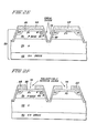
- FIGURE 1A is a schematic view in cross-section of a prior art MOSFET:
- FIGURE 1A illustrates a prior art MOSFET 10 having many identical "cells", or repeated units of structure. For simplicity, explicit reference is made only to the centrally depicted cell of the MOSFET 10.
- the MOSFET 10 is typically used to control the current level in an external circuit (not shown), which is connected between its SOURCE and drain electrodes 12 and 14.
- the "gate" or control electrode 16 normally determines such current level, depending upon the amplitude of a control voltage impressed on it.
- Normal operation of the MOSFET 10 is subject, however, to the adverse effect of turn-on of its inherent parasitic N-P-N transistor, formed from N region 18, P BASE 20, and N + SOURCE 22. If the parasitic transistor turns-on, the MOSFET 10 begins to lose control of the external circuit current level. The parasitic transistor can become so conductive that all control of the external circuit current level is lost, and the MOSFET 10 itself can be destroyed.
- the parasitic transistor will turn-on if any portion of the P-N junction 24 between P BASE 20 and N + SOURCE 22 (e.g., between locations A and C) becomes forward biased by more than about 0.7 volts (for a silicon device).
- an electrical short between P BASE 20 and N SOURCE 22 is implemented at location B by source electrode 12.
- the voltage drop across the P-N junction 24 at location B is held to 0 volts.
- This condition does not hold for portions of the P-N junction 24 remote from location B.
- the voltage drop between locations A and C can rise above 0.7 volts if sufficient hole current flows between locations A and B in P BASE 20, resulting in a voltage drop from location A to B.
- FIGURE 1B shows a semiconductor body 28 including N + DRAIN 30, N region 18, and P BASE 20.
- a diffusion barrier or mask 32 such as silicon diaxide,is provided on the upper surface 33 of the body 28.
- the diffusion mask 32 defines diffusion window 34 (and adjacent diffusion windows).
- An N diffusion of dopant through the upper surface 33 is performed and forms the N SOURCE 22 (shown in phantom).
- an etch barrier or mask 38 such as silicon dioxide, is next provided on the upper surface 33.
- the etch mask 38 defines an etch window 40.
- An etchant is applied through the etch window 40 to remove semiconductor material from the body 28 to form groove 42 (shown in phantom), necessary for implementing the completed MOSFET 10 (FIG.1).
- Proper construction of the N SOURCE 22 requires that the etch window 40 be aligned as closely as is feasible to the center of the N SOURCE 22. However, this alignment step is extremely delicate, since the dimensions involved are exceedingly minute (e.g., on the order of 5 microns).
- the foregoing alignment step is delicate, precise alignment is not consistently attainable. Consequently, the etch window 40 falls at random within a minimum alignment tolerance 44.
- the completed N SOURCE 22 must be lengthy. This, however, increases the risk of the parasitic transistor turning on.
- a further drawback of having the N + SOURCE 22 lengthy is that the individual size of each cell in the MOSFET 10 is increased. This undesirably limits the amount of current that the MOSFET 10 can carry, and reduces the manufacturing yield of operable MOSFETs. Additionally, the inclusion of the foregoing delicate alignment step further reduces the manufacturing yield of operable MOSFETs.
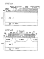
- FIGURES 2A-2G inclusive illustrating a preferred method of fabricating a MOSFET.
- N DRAIN 52 typically comprises a substrate layer, with N-type layer 54 epitaxially grown on N + DRAIN 52, and P BASE 56 . epitaxially grown (or diffused into) the N-type layer 54.
- This construction is typical of "power" MOSFET, or MOSFETs designed to carry substantial levels of current. Our invention, however, can be practised with non-power devices.
- FIGURE 2A additionally illustrates a processing step for implementing P region 58 (shown in phantom).
- P region 58 shown in phantom
- P-type dopant such as boron
- a thick layer e.g.,2 micrometers of silicon dioxide,or other suitable diffusion resistant material, to the body upper surface 60, and pattern it using photolithography (a known technique) to provide a mask 62, as shown in FIGURE 2B, which defines a window 64.
- This etching need not be anisotropic, or directional.
- a suitable etching technique for example, is planar plasma etching.
- N-type dopant such as phosphorus
- the mask 62 serves an additional purpose as an etch barrier or mask, as shown in FIGURE 2D.
- the etchant is dependent upon the crystal orientation of the silicon body 50 , such orientation being (100).
- Such etchant does not undercut beneath the mask 62 and hence/completely etch away the N + SOURCE 66. This allows portions of N + SOURCE 66 beneath the mask 62, or "shoulders" 72, to remain intact.
- an insulating layer 73 to cover the surface of the groove 68.
- a preferred way of implementing the layer 73 is by growing it as an oxide of the semiconductor body 50. This is accomplished by exposing the body 50 to oxygen at high temperature.
- the P region 58 advantageously completes an electrical short between P BASE 56 and N + SOURCE 66,e.g., location E.
- This electrical short has three components.
- One component comprises the junction 82 between the P region 58 and the N SOURCE 66,which junction forms a "tunnel" junction, because each of the foregoing regions is heavily doped(i.e.,each has a doping concentration in excess of about 10 19 dopant atoms per cc of silicon).
- the tunnel junction 82 constitutes a low resistance connection between the N + SOURCE 66 and the P + region 58,at least during normal device operation.
- Tunnel junctions are discussed more fully,for example, in S.M.Sze,Physics of Semiconductor Devices, New York: Wiley-Interscience,1969,Chapter 4.
- the second component of the electrical short /loca ti on E comprises the junction 84,between P BASE 56 and P + region 58.
- the junction 84 constitutes a low resistance path between the P BASE 56 and the P + region 58, because holes can freely pass from the P BASE.56 to the P + region 58.
- the third component of the electrical short/location E comprises the P region 58, in the vicinity/location E, between the tunnel junction 82 and the junction 84.
- the region 58 is highly doped, and so constitutes a low resistance path between the junctions 82 and 84. All three of the foregoing low resistance paths collectively provide a low resistance path between the P BASE 56 and the N SOURCE 66, thus implementing the electrical short between these regions at location E.
- the tunnel junction 82 is also part of a low resistance path between the N SOURCE 66 and the source electrode 76, such low resistance path also including the highly-doped P region 58. Because the P region 58 is highly-doped and thus conductive, the source electrode 76 only needs to make contact with it at isolated locations.
- the MOSFET 80 possesses significant advantages over the prior art MOSFET 10, described above.
- the length of the N + SOURCE 66 is drastically reduced compared to the prior art. This is because all but the shoulders 72 of the N SOURCE 66 have been etched away. Accordingly, the electrical short at location E is highly effective. This is because hole current flowing in P BASE 56, from location D to location E, produces only a low voltage drop because the distance D-E is short. Accordingly, it is unlikely that any portion of.P-N junction 86 between P BASE 56 and N + SOURCE 66 (e.g., between locations D and F) can become excessively forward biased. This greatly reduces the likelihood of turn-on of the parasitic bipolar transistor in the MOSFET 80(i.e., the transistor formed by N-region 54, P BASE 56, and N SOURCE 66).
- MOSFETs made by our invention allow reduced cell size using present state of the art processing techniques. For a typical MOSFET, this size reduction amounts to about 50 percent. This dramatically increases the manufacuring yield of operable MOSFETs, which makes them less increases the costly. Additionally, the size reduction/current-carrying capability of a 500 volt-rated MOSFET by about 30 percent, and of a 50 volt-rated MOSFET by about 100 percent. Accordingly, smaller and less costly MOSFETs made in accordance with our invention are needed in a given application, compared with MOSFETs made by the conventional methods.
- our foregoing method of fabricating the MOSFET 80 could be modified, for example, by employing an anisotropic etchant other than the preferred orientation-dependent etchant such mentioned above.
- suitable etchants must allow shoulders 72 of the N + SOURCE 66 to remain intact.
- these other suitable etchants include a vertically collimated beam of reactive ions and a planar plasma etchant. These etchants tend to form a groove 68 (FIGURE 2D) having more of a U-shape than a V-shape. These etchants do not to be require the semiconductor body/(100) crystal oriented, as does the preferred, orientation-dependent etchant.
- a further modification of our foregoing method of fabricating the MOSFET 80 is to form the gate electrode 74 from a conductive refractory material, rather than by metallization.
- Suitable refractory materials include highly-doped polysilicon, molybdenum silicide and tungsten silicide. If polysilicon were used, our foregoing method could be altered as follows, by way of example. After the insulating layer 62 of FIGURE 2E has been formed, polysilicon (not illustrated) is deposited on the upper surface of the structure shown in FIGURE 2E. The polysilicon layer is highly doped to make it conductive, and is patterned to remove it from the desired locations for the source electrode. A layer of oxide is grown on the polysilicon by exposing it to oxygen at high temperature, openings similar to openings 75 (FIGURE 2F) are made, and, finally, metallization is applied to the upper surface of the modified structure to implement the source electrode.
- IGR insulated gate rectifier
- FIGURE 3 Another appropriate semiconductor device is an insulated gate rectifier (IGR), shown in FIGURE 3.
- the IGR 90 includes a.P + substrate 92, in contrast with the N + DRAIN substrate 52 of the MOSFET 80. With this substitution, the foregoing method of fabricating the present embodiment of our invention is applicable to IGR 90.
- the parasitic N-P-N transistor in the IGR 90 formed by N region 94, P region 96, and N region 97, is electrically coupled in thyristor fashion to a parasitic P-N-P transistor -- namely, the transistor formed by P region 92, N region 94, and P region 96. Accordingly, these parasitic transistors can "latch", or become established in a current-conducting state, if the N-P-N (or upper transistor) is allowed to turn on. Once the IGR 90 becomes latched, control of its current level by its gate 98 is totally lost.
- This risk of the IGR 90 becoming latched is always present when the IGR 90 is in its active or current- carrying state.
- Our invention greatly diminishes this risk by preventing the N-P-N transistor from becoming excessively active. This is because the distance H-I in P region 96 along P-N junction 100 is so short that P-N junction 100 (e.g., between locations H and J)cannot become excessively forward biased. Additionally, the IGR 90 can have a reduced cell size, compared to IGRs made from prior art methods, enabling the IGR 90 to be made more economically and carry more current.
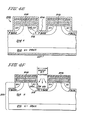
- FIGURE 4A a semiconductor body 200,typically of silicon.
- the body 200 typically comprises a substrate 202, constituting an N DRAIN,and an N region 204, typically epitaxially grown on the N + DRAIN 202.
- This construction is typical of power MOSFETs, although our invention can be practised with non-power devices.
- an insulating layer 206 On the upper surface 205 of the body 200, we form an insulating layer 206, suitably by growing an oxide on the body 200.
- a conductive refractory material 208 (shown partially broken away) on the insulating layer 206.
- the refractory material comprises polysilicon we dope it highly to make it conductive.
- insulating layer 210 on the upper surface of the refractory material 208.
- the insulating layer 210 suitably comprises an oxide grown thereon.
- the layer 211 comprises a material, such as aluminum oxide, which is resistant to an etchant,that etches through silicon dioxide and silicon during a processing step described below.
- the mask 216 defines a window 217 and serves as a diffusion barrier when we next make a P-type diffusion through the window 217 to form P BASE 218 (shown in phantom).
- N + SOURCE 220 (shown in phantom).
- the N diffusion extends laterally beneath the refractory material 208, i.e., in region 222, approximately the same distance as it diffuses vertically downward. This diffusion occurs at high temperature in an oxidizing atmosphere.
- the exposed surfaces 219(shown in FIGURE 4B) of the refractory material 208 become oxidized so that the refractory material 208 becomes surrounded by insulating material, as shown in FIGURE 4C.
- the exposed portions of the semiconductor body surface 205(shown in FIGURE 4B) becomes oxidized to form oxide layer 221,(shown in FIGURE 4C).
- this etchant suitably comprises a vertically collimated beam of reactive ions or a planar plasma etchant, and forms a generally U-shaped groove 224.
- a V-shaped groove (not illustrated) could be formed by first using one of the preceeding etchants to remove the oxide layer 221, and then using an orientation-dependent etchant (such as a mixture of potassium hydroxide and isopropanol, in the approximate ratio of 3 to 1) to etch into the semiconductor body 200.
- an orientation-dependent etchant such as a mixture of potassium hydroxide and isopropanol, in the approximate ratio of 3 to 1
- the body 200 would need to have a (100) crystal orientation, and an insulating layer 210 (FIGURE 4A) is necessary, because the layer 211 (at least where it comprises aluminum oxide) is removed by the orientation-dependent etchant (at least where it comprises potassium hydroxide).
- MOSFET 228 as shown in FIGURE 4E by applying metallization 226 and 227 to the upper and lower surfaces, respectively, of the structure of FIGURE 4D.
- An electrical short in the MOSFET 228 exists at location A, where the metallization 226 electrically connects the P BASE 218 to the N + SOURCE 220.
- the present embodiment of our invention applies to semiconductor devices other than MOSFETs.
- Another appropriate semiconductor device is an insulated gate rectifier (IGR) 240, as shown in FIGURE 5.
- the IGR 240 is similar to the MOSFET 238 (FIGURE 4G), except that the IGR 240 includes a P substrate 242, in contrast with the N + DRAIN substrate 202 of the MOSFET 238. With this sub- method of stitution, the foregoing/fabricating of the present embodiment of our. invention is applicable to the IGR 240.
Applications Claiming Priority (2)
| Application Number | Priority Date | Filing Date | Title |
|---|---|---|---|
| US36731682A | 1982-04-12 | 1982-04-12 | |
| US367316 | 1982-04-12 |
Publications (3)
| Publication Number | Publication Date |
|---|---|
| EP0091686A2 true EP0091686A2 (fr) | 1983-10-19 |
| EP0091686A3 EP0091686A3 (en) | 1986-03-19 |
| EP0091686B1 EP0091686B1 (fr) | 1989-06-28 |
Family
ID=23446680
Family Applications (1)
| Application Number | Title | Priority Date | Filing Date |
|---|---|---|---|
| EP83103501A Expired EP0091686B1 (fr) | 1982-04-12 | 1983-04-11 | Dispositif semi-conducteur ayant une région diffusée à longueur réduite et procédé pour la fabrication de la région |
Country Status (3)
| Country | Link |
|---|---|
| EP (1) | EP0091686B1 (fr) |
| JP (1) | JPH0626253B2 (fr) |
| DE (1) | DE3380136D1 (fr) |
Cited By (11)
| Publication number | Priority date | Publication date | Assignee | Title |
|---|---|---|---|---|
| EP0094891A2 (fr) * | 1982-05-20 | 1983-11-23 | Fairchild Semiconductor Corporation | Procédé pour la fabrication d'une structure verticale MOSFET de puissance |
| EP0159663A2 (fr) * | 1984-04-26 | 1985-10-30 | General Electric Company | Thyristors, transistors à effet de champ à électrode de porte isolée et MOSFETs à haute densité commandés par effet de champ utilisant une structure MOS formée dans une rainure de type V et procédé de fabrication |
| WO1985005224A1 (fr) * | 1984-05-02 | 1985-11-21 | Bell Telephone Manufacturing Company Naamloze Venn | Dispositif et agencement semi-conducteurs |
| EP0164096A2 (fr) * | 1984-06-08 | 1985-12-11 | Eaton Corporation | Transistor à effet de champ du type latéral bidirectionnel de puissance comportant une pluralité de canaux empilés pourvus de rainures |
| EP0164095A2 (fr) * | 1984-06-08 | 1985-12-11 | Eaton Corporation | Transistor de puissance à effet de champ du type vertical, bidirectionnel et empilé |
| EP0202477A2 (fr) * | 1985-04-24 | 1986-11-26 | General Electric Company | Procédé pour former des courts-circuits électriques entre des régions voisines dans un dispositif semi-conducteur à gâchette isolée |
| EP0326187A3 (fr) * | 1982-05-20 | 1989-09-27 | Fairchild Semiconductor Corporation | Structure MOSFET à puissance |
| GB2227605A (en) * | 1989-01-30 | 1990-08-01 | Philips Electronic Associated | A vertical field effect semiconductor device |
| GB2303487A (en) * | 1995-07-21 | 1997-02-19 | Plessey Semiconductors Ltd | Semiconductor devices with recessed emitters |
| US5701023A (en) * | 1994-08-03 | 1997-12-23 | National Semiconductor Corporation | Insulated gate semiconductor device typically having subsurface-peaked portion of body region for improved ruggedness |
| WO2001006568A2 (fr) * | 1999-07-20 | 2001-01-25 | Koninklijke Philips Electronics N.V. | Transistors a effet de champ, a grille et tranchee, et leur procede de fabrication |
Families Citing this family (9)
| Publication number | Priority date | Publication date | Assignee | Title |
|---|---|---|---|---|
| JPH0693512B2 (ja) * | 1986-06-17 | 1994-11-16 | 日産自動車株式会社 | 縦形mosfet |
| JP2615667B2 (ja) * | 1987-09-28 | 1997-06-04 | 日産自動車株式会社 | Mos電界効果トランジスタの製造方法 |
| JPH01108775A (ja) * | 1987-10-21 | 1989-04-26 | Nec Kansai Ltd | 縦型電界効果トランジスタ |
| JPH0817233B2 (ja) * | 1987-11-11 | 1996-02-21 | 三菱電機株式会社 | 絶縁ゲート型バイポーラトランジスタ |
| JP3260944B2 (ja) * | 1993-12-15 | 2002-02-25 | 三菱電機株式会社 | 電圧駆動型サイリスタおよびその製造方法 |
| KR100824205B1 (ko) * | 2006-12-26 | 2008-04-21 | 매그나칩 반도체 유한회사 | Dmos 트랜지스터 및 그 제조방법 |
| JP2009302510A (ja) * | 2008-03-03 | 2009-12-24 | Fuji Electric Device Technology Co Ltd | トレンチゲート型半導体装置およびその製造方法 |
| JP2012084739A (ja) | 2010-10-13 | 2012-04-26 | Sumitomo Electric Ind Ltd | 半導体装置およびその製造方法 |
| JP5630552B2 (ja) * | 2013-10-15 | 2014-11-26 | 富士電機株式会社 | 炭化珪素半導体装置およびその製造方法 |
Citations (3)
| Publication number | Priority date | Publication date | Assignee | Title |
|---|---|---|---|---|
| US3975221A (en) * | 1973-08-29 | 1976-08-17 | American Micro-Systems, Inc. | Low capacitance V groove MOS NOR gate and method of manufacture |
| FR2487583A1 (fr) * | 1980-07-25 | 1982-01-29 | Thomson Csf | Procede de fabrication d'un transistor a effet de champ a rainure |
| GB2088631A (en) * | 1980-12-02 | 1982-06-09 | Gen Electric | Field effect controlled semiconductor rectifier |
Family Cites Families (4)
| Publication number | Priority date | Publication date | Assignee | Title |
|---|---|---|---|---|
| JPS55110066A (en) * | 1979-02-17 | 1980-08-25 | Fujitsu Ltd | Semiconductor device |
| US4379305A (en) * | 1980-05-29 | 1983-04-05 | General Instrument Corp. | Mesh gate V-MOS power FET |
| JPS58106870A (ja) * | 1981-12-18 | 1983-06-25 | Nissan Motor Co Ltd | パワ−mosfet |
| JPS58168277A (ja) * | 1982-03-30 | 1983-10-04 | Toshiba Corp | 絶縁ゲ−ト電解効果トランジスタ |
-
1983
- 1983-04-11 DE DE8383103501T patent/DE3380136D1/de not_active Expired
- 1983-04-11 EP EP83103501A patent/EP0091686B1/fr not_active Expired
- 1983-04-12 JP JP58063130A patent/JPH0626253B2/ja not_active Expired - Lifetime
Patent Citations (3)
| Publication number | Priority date | Publication date | Assignee | Title |
|---|---|---|---|---|
| US3975221A (en) * | 1973-08-29 | 1976-08-17 | American Micro-Systems, Inc. | Low capacitance V groove MOS NOR gate and method of manufacture |
| FR2487583A1 (fr) * | 1980-07-25 | 1982-01-29 | Thomson Csf | Procede de fabrication d'un transistor a effet de champ a rainure |
| GB2088631A (en) * | 1980-12-02 | 1982-06-09 | Gen Electric | Field effect controlled semiconductor rectifier |
Non-Patent Citations (2)
| Title |
|---|
| IBM TECHNICAL DISCLOSURE BULLETIN, vol. 22, no. 8B, January 1980, pages 3705,3706, New York, US; R.C.VARSHNEY: "Self-Aligned VMOS structure using reactive ion etching" * |
| IEEE TRANSACTIONS ON ELECTRON DEVICES, vol. ED-25, no. 10, October 1978, pages 1185-1193, IEEE, New York, US; K.E.BEAN: "Anisotropic etching of silicon" * |
Cited By (19)
| Publication number | Priority date | Publication date | Assignee | Title |
|---|---|---|---|---|
| EP0094891A3 (en) * | 1982-05-20 | 1985-07-31 | Fairchild Camera & Instrument Corporation | Power mosfet structure and method of fabricating it |
| EP0094891A2 (fr) * | 1982-05-20 | 1983-11-23 | Fairchild Semiconductor Corporation | Procédé pour la fabrication d'une structure verticale MOSFET de puissance |
| EP0326187A3 (fr) * | 1982-05-20 | 1989-09-27 | Fairchild Semiconductor Corporation | Structure MOSFET à puissance |
| EP0159663A3 (fr) * | 1984-04-26 | 1987-09-23 | General Electric Company | Thyristors, transistors à effet de champ à électrode de porte isolée et MOSFETs à haute densité commandés par effet de champ utilisant une structure MOS formée dans une rainure de type V et procédé de fabrication |
| EP0159663A2 (fr) * | 1984-04-26 | 1985-10-30 | General Electric Company | Thyristors, transistors à effet de champ à électrode de porte isolée et MOSFETs à haute densité commandés par effet de champ utilisant une structure MOS formée dans une rainure de type V et procédé de fabrication |
| WO1985005224A1 (fr) * | 1984-05-02 | 1985-11-21 | Bell Telephone Manufacturing Company Naamloze Venn | Dispositif et agencement semi-conducteurs |
| US4779125A (en) * | 1984-05-02 | 1988-10-18 | Alcatel N.V. | Semiconductor device and arrangement |
| EP0164096A2 (fr) * | 1984-06-08 | 1985-12-11 | Eaton Corporation | Transistor à effet de champ du type latéral bidirectionnel de puissance comportant une pluralité de canaux empilés pourvus de rainures |
| EP0164096A3 (fr) * | 1984-06-08 | 1987-01-14 | Eaton Corporation | Transistor à effet de champ du type latéral bidirectionnel de puissance comportant une pluralité de canaux empilés pourvus de rainures |
| EP0164095A3 (fr) * | 1984-06-08 | 1987-01-07 | Eaton Corporation | Transistor de puissance à effet de champ du type vertical, bidirectionnel et empilé |
| EP0164095A2 (fr) * | 1984-06-08 | 1985-12-11 | Eaton Corporation | Transistor de puissance à effet de champ du type vertical, bidirectionnel et empilé |
| EP0202477A3 (fr) * | 1985-04-24 | 1988-04-20 | General Electric Company | Procédé pour former des courts-circuits électriques entre des régions voisines dans un dispositif semi-conducteur à gâchette isolée |
| EP0202477A2 (fr) * | 1985-04-24 | 1986-11-26 | General Electric Company | Procédé pour former des courts-circuits électriques entre des régions voisines dans un dispositif semi-conducteur à gâchette isolée |
| GB2227605A (en) * | 1989-01-30 | 1990-08-01 | Philips Electronic Associated | A vertical field effect semiconductor device |
| US5701023A (en) * | 1994-08-03 | 1997-12-23 | National Semiconductor Corporation | Insulated gate semiconductor device typically having subsurface-peaked portion of body region for improved ruggedness |
| US5897355A (en) * | 1994-08-03 | 1999-04-27 | National Semiconductor Corporation | Method of manufacturing insulated gate semiconductor device to improve ruggedness |
| GB2303487A (en) * | 1995-07-21 | 1997-02-19 | Plessey Semiconductors Ltd | Semiconductor devices with recessed emitters |
| WO2001006568A2 (fr) * | 1999-07-20 | 2001-01-25 | Koninklijke Philips Electronics N.V. | Transistors a effet de champ, a grille et tranchee, et leur procede de fabrication |
| WO2001006568A3 (fr) * | 1999-07-20 | 2001-09-07 | Koninkl Philips Electronics Nv | Transistors a effet de champ, a grille et tranchee, et leur procede de fabrication |
Also Published As
| Publication number | Publication date |
|---|---|
| EP0091686B1 (fr) | 1989-06-28 |
| DE3380136D1 (en) | 1989-08-03 |
| JPH0626253B2 (ja) | 1994-04-06 |
| JPS58202575A (ja) | 1983-11-25 |
| EP0091686A3 (en) | 1986-03-19 |
Similar Documents
| Publication | Publication Date | Title |
|---|---|---|
| EP0091686B1 (fr) | Dispositif semi-conducteur ayant une région diffusée à longueur réduite et procédé pour la fabrication de la région | |
| US4567641A (en) | Method of fabricating semiconductor devices having a diffused region of reduced length | |
| US5032532A (en) | Method for fabricating insulated gate semiconductor device | |
| US6872611B2 (en) | Method of manufacturing transistor | |
| US4791462A (en) | Dense vertical j-MOS transistor | |
| US4983535A (en) | Vertical DMOS transistor fabrication process | |
| KR100451450B1 (ko) | 바디 영역내에 트렌치 형상의 게이트-전극 및 추가 고도핑 층을 갖는 전계 효과 트랜지스터 | |
| JPH04146674A (ja) | 半導体装置及びその製造方法 | |
| US4115797A (en) | Integrated injection logic with heavily doped injector base self-aligned with injector emitter and collector | |
| US5034336A (en) | Method of producing insulated gate bipolar tranistor | |
| JP2001244462A (ja) | トランジスタ及びその製造方法 | |
| JPH0719838B2 (ja) | 半導体装置およびその製造方法 | |
| US4454523A (en) | High voltage field effect transistor | |
| JPH0817233B2 (ja) | 絶縁ゲート型バイポーラトランジスタ | |
| US5397905A (en) | Power semiconductor device having an insulated gate field effect transistor and a bipolar transistor | |
| US5179034A (en) | Method for fabricating insulated gate semiconductor device | |
| US5285094A (en) | Vertical insulated gate semiconductor device with less influence from the parasitic bipolar effect | |
| KR900007048B1 (ko) | 종형 mos 반도체장치 | |
| KR950003934B1 (ko) | 양방향성 수직 전원 mos소자 및 그 제조방법 | |
| US3860454A (en) | Field effect transistor structure for minimizing parasitic inversion and process for fabricating | |
| US5143859A (en) | Method of manufacturing a static induction type switching device | |
| JPH02178965A (ja) | 絶縁分離型電界効果半導体装置 | |
| US3753806A (en) | Increasing field inversion voltage of metal oxide on silicon integrated circuits | |
| JPH0613606A (ja) | 半導体装置 | |
| JPH11251590A (ja) | 高耐圧半導体デバイス |
Legal Events
| Date | Code | Title | Description |
|---|---|---|---|
| PUAI | Public reference made under article 153(3) epc to a published international application that has entered the european phase |
Free format text: ORIGINAL CODE: 0009012 |
|
| AK | Designated contracting states |
Designated state(s): CH DE FR GB LI NL SE |
|
| 17P | Request for examination filed |
Effective date: 19840323 |
|
| PUAL | Search report despatched |
Free format text: ORIGINAL CODE: 0009013 |
|
| AK | Designated contracting states |
Kind code of ref document: A3 Designated state(s): CH DE FR GB LI NL SE |
|
| 17Q | First examination report despatched |
Effective date: 19880202 |
|
| GRAA | (expected) grant |
Free format text: ORIGINAL CODE: 0009210 |
|
| AK | Designated contracting states |
Kind code of ref document: B1 Designated state(s): CH DE FR GB LI NL SE |
|
| REF | Corresponds to: |
Ref document number: 3380136 Country of ref document: DE Date of ref document: 19890803 |
|
| ET | Fr: translation filed | ||
| PLBE | No opposition filed within time limit |
Free format text: ORIGINAL CODE: 0009261 |
|
| STAA | Information on the status of an ep patent application or granted ep patent |
Free format text: STATUS: NO OPPOSITION FILED WITHIN TIME LIMIT |
|
| 26N | No opposition filed | ||
| EAL | Se: european patent in force in sweden |
Ref document number: 83103501.9 |
|
| PGFP | Annual fee paid to national office [announced via postgrant information from national office to epo] |
Ref country code: SE Payment date: 20010320 Year of fee payment: 19 |
|
| REG | Reference to a national code |
Ref country code: GB Ref legal event code: IF02 |
|
| PGFP | Annual fee paid to national office [announced via postgrant information from national office to epo] |
Ref country code: NL Payment date: 20020329 Year of fee payment: 20 |
|
| PGFP | Annual fee paid to national office [announced via postgrant information from national office to epo] |
Ref country code: FR Payment date: 20020401 Year of fee payment: 20 |
|
| PGFP | Annual fee paid to national office [announced via postgrant information from national office to epo] |
Ref country code: GB Payment date: 20020403 Year of fee payment: 20 Ref country code: CH Payment date: 20020403 Year of fee payment: 20 |
|
| PG25 | Lapsed in a contracting state [announced via postgrant information from national office to epo] |
Ref country code: SE Free format text: LAPSE BECAUSE OF NON-PAYMENT OF DUE FEES Effective date: 20020412 |
|
| PGFP | Annual fee paid to national office [announced via postgrant information from national office to epo] |
Ref country code: DE Payment date: 20020418 Year of fee payment: 20 |
|
| EUG | Se: european patent has lapsed |
Ref document number: 83103501.9 |
|
| PG25 | Lapsed in a contracting state [announced via postgrant information from national office to epo] |
Ref country code: LI Free format text: LAPSE BECAUSE OF EXPIRATION OF PROTECTION Effective date: 20030410 Ref country code: GB Free format text: LAPSE BECAUSE OF EXPIRATION OF PROTECTION Effective date: 20030410 Ref country code: CH Free format text: LAPSE BECAUSE OF EXPIRATION OF PROTECTION Effective date: 20030410 |
|
| PG25 | Lapsed in a contracting state [announced via postgrant information from national office to epo] |
Ref country code: NL Free format text: LAPSE BECAUSE OF EXPIRATION OF PROTECTION Effective date: 20030411 |
|
| REG | Reference to a national code |
Ref country code: GB Ref legal event code: PE20 |
|
| REG | Reference to a national code |
Ref country code: CH Ref legal event code: PL |