EP0088999A2 - Projectile à noyau perforant pour combattre des armures multicouches - Google Patents
Projectile à noyau perforant pour combattre des armures multicouches Download PDFInfo
- Publication number
- EP0088999A2 EP0088999A2 EP83102300A EP83102300A EP0088999A2 EP 0088999 A2 EP0088999 A2 EP 0088999A2 EP 83102300 A EP83102300 A EP 83102300A EP 83102300 A EP83102300 A EP 83102300A EP 0088999 A2 EP0088999 A2 EP 0088999A2
- Authority
- EP
- European Patent Office
- Prior art keywords
- core element
- projectile
- projectile according
- core
- region
- Prior art date
- Legal status (The legal status is an assumption and is not a legal conclusion. Google has not performed a legal analysis and makes no representation as to the accuracy of the status listed.)
- Granted
Links
- 239000002365 multiple layer Substances 0.000 title 1
- 238000013016 damping Methods 0.000 claims description 13
- 239000000463 material Substances 0.000 claims description 5
- 229910001092 metal group alloy Inorganic materials 0.000 claims description 4
- 230000035939 shock Effects 0.000 claims description 3
- 229910000831 Steel Inorganic materials 0.000 claims 1
- 239000002184 metal Substances 0.000 claims 1
- 239000010959 steel Substances 0.000 claims 1
- 230000003313 weakening effect Effects 0.000 abstract description 5
- 238000011144 upstream manufacturing Methods 0.000 abstract 1
- 230000002093 peripheral effect Effects 0.000 description 8
- 230000035515 penetration Effects 0.000 description 5
- 230000002028 premature Effects 0.000 description 3
- 229910045601 alloy Inorganic materials 0.000 description 2
- 239000000956 alloy Substances 0.000 description 2
- 238000005452 bending Methods 0.000 description 2
- 230000000694 effects Effects 0.000 description 2
- 229910001385 heavy metal Inorganic materials 0.000 description 2
- 230000002787 reinforcement Effects 0.000 description 2
- 230000015572 biosynthetic process Effects 0.000 description 1
- 230000006378 damage Effects 0.000 description 1
- 239000012634 fragment Substances 0.000 description 1
- 238000011835 investigation Methods 0.000 description 1
- WFKWXMTUELFFGS-UHFFFAOYSA-N tungsten Chemical compound [W] WFKWXMTUELFFGS-UHFFFAOYSA-N 0.000 description 1
- 229910052721 tungsten Inorganic materials 0.000 description 1
- 239000010937 tungsten Substances 0.000 description 1
Images

Classifications
-
- F—MECHANICAL ENGINEERING; LIGHTING; HEATING; WEAPONS; BLASTING
- F42—AMMUNITION; BLASTING
- F42B—EXPLOSIVE CHARGES, e.g. FOR BLASTING, FIREWORKS, AMMUNITION
- F42B12/00—Projectiles, missiles or mines characterised by the warhead, the intended effect, or the material
- F42B12/02—Projectiles, missiles or mines characterised by the warhead, the intended effect, or the material characterised by the warhead or the intended effect
- F42B12/04—Projectiles, missiles or mines characterised by the warhead, the intended effect, or the material characterised by the warhead or the intended effect of armour-piercing type
- F42B12/06—Projectiles, missiles or mines characterised by the warhead, the intended effect, or the material characterised by the warhead or the intended effect of armour-piercing type with hard or heavy core; Kinetic energy penetrators
Definitions
- the invention relates to an armor-piercing balancing projectile according to the preamble of patent claim 1.
- a projectile of the type mentioned is known from DE-PS 14 28 679. It has different armor-piercing pre-core elements in an envelope axially one behind the other and an armor-piercing main core element adjoining these on the back. Between the core elements, which consist of hard and / or heavy metal, layers of plastic-bonded hollow spheres or a light metal alloy are provided as shock-absorbing means. By arranging the different pre-core elements, a targeted mass reduction of the projectile arrangement is to be realized in such a way that, after penetration of a pre-armor while protecting the main core element against premature destruction due to shock wave stress against a main armor of the target, a sufficient projectile mass in the form of the main core element is available.
- missiles of the type mentioned at the outset are exposed to loads acting through multi-plate targets transverse to the longitudinal axis of the projectile, which regularly lead to premature bending of the missile.
- a penetration channel inclined towards the extension of the projectile trajectory can reach the main core element the main armor and thus affect the effect of the projectile in a very sensitive way.
- the invention has for its object to provide a projectile of the type mentioned, which is suitable to combat modern multi-plate targets with the greatest possible use of the energy inherent in the projectile.
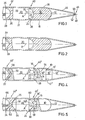
- a first exemplary embodiment has a first pre-core element 10 in the tip region and a second pre-core element 20, which is arranged axially downstream of this, to which a main core element 30 is connected on the rear side.
- a front surface 12 of the pre-core element 10 is designed as a hemispherical surface. It runs on the back into a circular cylindrical peripheral surface 18.
- a rear side surface 14 of the pre-core element 10 is designed as a hollow spherical cap, which is joined in the peripheral region by an annular surface 16 which crosses a longitudinal axis A of the projectile.
- a front surface 22 of the pre-core element 20 is designed as a hemispherical surface which is delimited in the base-side circumferential area by an annular surface 24. Between the mutually facing circular ring surfaces 16 and 24 there is an axial distance, not specified, which is to be assigned to a first intermediate region 40.
- a circular cylindrical peripheral surface 21 of the pre-core element 20 is of the same diameter as the peripheral surface 18.
- a rear surface 26 of the pre-core element 20 is designed as a hollow spherical cap and is delimited in the circumferential area by an annular surface 28 crossing the longitudinal axis A of the projectile.
- a main core element 30 adjoining on the rear is adapted with its front surface 32 to the rear surface 26 and is delimited in the peripheral region by an annular surface 34 crossing the longitudinal axis A of the projectile.
- An axial distance, not specified, between the mutually facing circular ring surfaces 28 and 34 is to be assigned to a second intermediate area 42.
- a sleeve 36 extends axially over the two pre-core elements 10 and 20 and at least one unspecified front area of the main core element 30 and encloses them.
- a tip element 46 with a hemispherical head 48 is fixed with a circular cylindrical bolt 50 in a central axial bore 52.
- a second exemplary embodiment differs from that according to FIG. 1 by the formation of a rear side surface 27 of the front core element 20 and a front surface 33 of the main core element 30.
- the latter is circular-conical and funnel-shaped, the surfaces 27 and 33 touch each other.
- the pre-core element 10 has a first circular-cylindrical region 10 'and a second circular-cylindrical region "of comparatively larger diameter adjoining the rear.
- the circumferential surface 18 of the region 10 is delimited on the rear by a narrow truncated cone surface 16''over which a circular cylindrical region 10''protrudes, which continues in a rear part with a hemispherical surface 14 '.
- the pre-core element 20 is adapted with a front hollow spherical surface 22 "of the hemispherical surface 14 'and is delimited in the circumferential area by a circular ring surface 24 crossing the longitudinal axis A of the projectile 27 "limited.
- An unspecified axial distance between the surfaces 16 "and 24 is to be assigned to a first intermediate region 40.
- Circular cylindrical area 39 has an external thread 39 'to which it is attached on the back a groove 31 connects.
- the casing 36 extends from a rear edge 37 in the immediate vicinity of an internal thread, which corresponds to the external thread 39 'and is not designated in any more detail, to the ballistic hood 44.
- a second intermediate region 42 is essentially formed by the surfaces 27 "and 33' and the thread 39 ', while a predetermined breaking point 38 designed as a wall weakening of the shell 36 is arranged in the first intermediate region 40.
- the shell 36 extends with substantially the same wall thickness over the region 10 "of the pre-core element 10 and points in the vicinity of the region 10 'A reinforcement 45 with a circular cylindrical inner surface 45' of smaller inner diameter.
- the reinforcement 45 can already be assigned to a ballistic hood 44, the tip design of which corresponds to that of the aforementioned exemplary embodiments.
- the screw connection of the sleeve 36 to the main core element 30 advantageously allows one or both of the pre-core elements 10, 20 to be replaced, for example to adapt to a particular target to be combated.
- a pre-core element 10 in turn has two circular cylindrical regions 10 ′, 10 ′′ of different diameters.
- the latter is delimited by a rear surface 14 designed as a hollow spherical cap with a circumferential annular surface 16 that crosses the longitudinal axis A of the floor 14, a hemispherical damping element 54 is fitted on the front side.
- the damping element 54 has a circular cylindrical receptacle for a front region of the front core element 20 with a circular end face 22 and a circumferential surface 23, which meet in a circular edge 22 ', in a rear surface, which is not designated in any more detail.
- a pin formed in this way protrudes over an annular surface 24 ', the peripheral region of which is not covered by the damping element 54.
- An axial distance between the surfaces 16 and 24, like the damping element 54, is to be assigned to a first intermediate region 40 '.
- the front core element 20 is bounded on the back by a circular funnel surface 27, to which a damping element 56 is adapted.
- the latter is designed in the shape of a circular funnel with a predetermined wall thickness and is adapted on the back to a circular conical surface 33 of the main core element 30.
- the damping element 56 is to be assigned to a second intermediate area 42 ′, while a predetermined breaking point 38 formed as a wall weakening of the casing 36 is included in the first intermediate area.
- the pre-core element 10 has a hemispherical front surface 12 and a central rear surface 14 'which crosses the longitudinal axis A of the projectile.
- a circular cylindrical surface 15 projects beyond the latter and is delimited in the peripheral region by an annular surface 16 '.
- a damping element 58 is adapted with a front region of the rear side 14 ', 15, 16' of the front core element 10, which is not specified in any more detail, and is delimited on the rear side by a surface 58 'in the form of a spherical cap, to which an annular surface 60 which crosses the longitudinal axis A of the floor is connected on the circumference .
- the pre-core element 20 is designed essentially circular-cylindrical, the circular-cylindrical region being delimited by a circular ring surface 24 on the front and a circular ring surface 25 on the rear. Over the former is a spherical cap with a front surface 22 which is adapted to the surface 58 'of the damping layer 58. An axial distance between the circular ring surfaces 60, which is not specified in any more detail and 24 is to be assigned to a first intermediate region 40 '. A hemispherical part with a rear surface 26 'protrudes beyond the rear circular surface 25. With a predetermined axial distance, a front region of the main core element 30 adjoins with a surface 32, formed in mirror image.
- the damping element 62 is designed on the tip side in accordance with the exemplary embodiments described above.
- a shell 36 is essentially of the same wall thickness over its entire length
- the sixth exemplary embodiment differs according to FIG. 6 through a sleeve 36 ', the wall thickness of which increases substantially continuously from a front edge 36 "to an area 37" with the same outside diameter.
- the sleeve 36' has an external thread 37 for releasable Connection to the ballistic hood 44.
- the latter is provided in a region 45 with a circular cylindrical inner surface 45 'which extends to an edge 43.
- a pre-core element 10 has a circular cylindrical region 10 ′ on the front side with a circumferential surface 13 ′ adapted to the inner surface 45 ′.
- a front surface 12 ° is delimited by a circular edge 13 in which the surfaces 12 ′ and 13 ′ collide.
- At the back of the area 10 there is an area 10 ′′ frustoconical shape.
- a pre-core element 20 (like the following pre-core elements 70 ... 80) is also designed as a circular cone frustum. Not abbreviated planar abutting surfaces of the aforementioned pre-core elements are each of the same size.
- a front annular surface 34 'of area 30 is in close contact with surface 37'.
- the area 30 ' has an external thread 39' and the sleeve 36 'has the corresponding internal thread, not designated in any more detail.
- the arrangement described allows, if necessary, a field-like replacement of the pre-core elements 10, 20, 70 ... 80 to adapt to a particular target. There are advantageously no special tools for this required. Since the largest diameter of the pre-core element 10 provides a corresponding penetration area in a pre-armor, the subsequent pre-core elements 20, 70 ... 80 can be effective against numerous armor elements arranged after the pre-armor without significant hindrance. This favors the effectiveness of the main core member 30 against main armor.
- the threads 37 and 39 ' are assigned to the respective intermediate areas 40 "and 42".
- an advantageous mass ratio of 1: 12: 6 is particularly to be mentioned, in connection with a corresponding arrangement the first numerical value of the first preliminary core element 10, the second numerical value of the preliminary core element 20 and the third numerical value of the Main core element 30 is assigned.
- the main core element 30 is preferably made of a high-strength, ductile shear metal alloy, for example a sintered alloy containing a high proportion of tungsten, while the two pre-core elements consist of a corresponding material with lower ductility. However, this can also be done when using damping elements first pre-core element 10 can be made from a ductile heavy metal alloy.
- the core elements can move in their mutually facing and articulated regions, namely in the intermediate regions 40, 42; 40 ', 42', pivot against each other.
- the sleeve 36 made of ductile material of sufficient strength, can absorb part of the transverse forces through deformation and ensures the greatest possible frictional connection between the adjacent surfaces of the core elements. This ensures that an axial impact component directed against the target is sufficient Size remains effective.
- target break point 38 is advantageously only effective when the intermediate area in question gets into a penetration channel on the target side, which results from the effect of pre-core element 10 and is inclined against the projectile flight path in the majority of the cases examined.
- envelope design according to FIG. 6 can advantageously also be applied to the exemplary embodiments according to FIGS. 1 to 5.
Priority Applications (1)
| Application Number | Priority Date | Filing Date | Title |
|---|---|---|---|
| AT83102300T ATE27487T1 (de) | 1982-03-17 | 1983-03-09 | Panzerbrechende wuchtgeschossanordnung, insbesondere zum bekaempfen von mehrplattenzielen. |
Applications Claiming Priority (2)
| Application Number | Priority Date | Filing Date | Title |
|---|---|---|---|
| DE3209594A DE3209594A1 (de) | 1982-03-17 | 1982-03-17 | Panzerbrechendes wuchtgeschoss insbesondere zum bekaempfen von mehrplattenzielen |
| DE3209594 | 1982-03-17 |
Related Child Applications (1)
| Application Number | Title | Priority Date | Filing Date |
|---|---|---|---|
| EP87115879.6 Division-Into | 1983-03-09 |
Publications (3)
| Publication Number | Publication Date |
|---|---|
| EP0088999A2 true EP0088999A2 (fr) | 1983-09-21 |
| EP0088999A3 EP0088999A3 (en) | 1983-11-23 |
| EP0088999B1 EP0088999B1 (fr) | 1987-05-27 |
Family
ID=6158425
Family Applications (1)
| Application Number | Title | Priority Date | Filing Date |
|---|---|---|---|
| EP83102300A Expired EP0088999B1 (fr) | 1982-03-17 | 1983-03-09 | Projectile à noyau perforant pour combattre des armures multicouches |
Country Status (4)
| Country | Link |
|---|---|
| US (2) | US4724769A (fr) |
| EP (1) | EP0088999B1 (fr) |
| AT (1) | ATE27487T1 (fr) |
| DE (2) | DE3209594A1 (fr) |
Cited By (3)
| Publication number | Priority date | Publication date | Assignee | Title |
|---|---|---|---|---|
| GB2168133A (en) * | 1984-11-27 | 1986-06-11 | Diehl Gmbh & Co | A warhead, missile or projectile |
| EP0853228A1 (fr) * | 1997-01-14 | 1998-07-15 | Oerlikon Contraves Pyrotec AG | Projectile et son procédé de fabrication |
| EP3591332A1 (fr) * | 2018-07-06 | 2020-01-08 | TDW Gesellschaft für verteidigungstechnische Wirksysteme mbH | Pénétrateur comprenant un corps, une tête et un amortisseur entre les deux |
Families Citing this family (19)
| Publication number | Priority date | Publication date | Assignee | Title |
|---|---|---|---|---|
| US5008071A (en) * | 1988-01-04 | 1991-04-16 | Gte Products Corporation | Method for producing improved tungsten nickel iron alloys |
| DE4016051C2 (de) * | 1990-05-18 | 1994-10-06 | Rheinmetall Gmbh | Mantelpenetrator |
| DE4023482A1 (de) * | 1990-07-24 | 1992-01-30 | Rheinmetall Gmbh | Unterkalibriges wuchtgeschoss |
| US5817969A (en) * | 1994-08-26 | 1998-10-06 | Oerlikon Contraves Pyrotec Ag | Spin-stabilized projectile with payload |
| SE508476C2 (sv) | 1996-04-26 | 1998-10-12 | Bofors Carl Gustaf Ab | Finkaliberprojektil |
| US6662726B1 (en) * | 1999-03-08 | 2003-12-16 | General Dynamics Ordnance And Tactical Systems, Inc. | Kinetic energy penetrator |
| US20050109234A1 (en) * | 2001-08-23 | 2005-05-26 | Lloyd Richard M. | Kinetic energy rod warhead with lower deployment angles |
| US7201104B2 (en) * | 2002-08-21 | 2007-04-10 | Ra Brands, L.L.C. | Lead attached sabot slug |
| FR2860580B1 (fr) * | 2003-10-03 | 2005-12-16 | Giat Ind Sa | Munition anti bunker |
| EP1737728A4 (fr) | 2003-10-14 | 2009-07-08 | Raytheon Co | Systeme de contre mesure de mine |
| US7503261B2 (en) * | 2004-01-30 | 2009-03-17 | Oerlikon Cantraves Pyrotec Ag | Universal KE projectile, in particular for medium caliber munitions |
| US20090320711A1 (en) * | 2004-11-29 | 2009-12-31 | Lloyd Richard M | Munition |
| US8707868B2 (en) | 2006-11-30 | 2014-04-29 | The United States Of America As Represented By The Secretary Of The Navy | Pre-compressed penetrator element for projectile |
| USH2230H1 (en) | 2006-11-30 | 2009-08-04 | The United States Of America As Represented By The Secretary Of The Navy | Ceramic and stacked penetrator against a hardened target |
| DE102009050162A1 (de) * | 2009-10-21 | 2011-04-28 | TDW Gesellschaft für verteidigungstechnische Wirksysteme mbH | Dämpfungsvorrichtung für Einbauteile in Penetratoren |
| FR2987891B1 (fr) * | 2012-03-06 | 2014-09-26 | Nexter Munitions | Projectile sous calibre a structure de tete amenagee |
| US20170138712A1 (en) * | 2015-11-12 | 2017-05-18 | Randy S. Teig | Mechanically adaptable projectile and method of manufacturing the same |
| US20180321021A1 (en) * | 2015-11-12 | 2018-11-08 | Randy S. Teig | Mechanically adaptable projectile and method of manufacturing the same |
| FR3110687B1 (fr) | 2020-05-20 | 2022-05-27 | Nexter Munitions | Projectile sous calibré et procédé de neutralisation d'un objectif en mettant en oeuvre un tel projectile. |
Citations (5)
| Publication number | Priority date | Publication date | Assignee | Title |
|---|---|---|---|---|
| GB594517A (en) * | 1940-09-04 | 1947-11-13 | Charles Dennistoun Burney | Improvements in or relating to aeroplane and other bombs or projectiles |
| FR1388760A (fr) * | 1962-11-20 | 1965-02-12 | Projectile à noyau dur | |
| GB1095992A (en) * | 1959-04-14 | 1967-12-20 | Secr Defence | Improvements in or relating to projectiles |
| DE1428679C1 (de) * | 1964-12-29 | 1977-09-15 | Deutsch Franz Forsch Inst | Hartkerngeschoss zur Bekaempfung von Panzerzielen |
| GB2036934A (en) * | 1978-11-23 | 1980-07-02 | France Armed Forces | Armour - penetrating projectile |
Family Cites Families (7)
| Publication number | Priority date | Publication date | Assignee | Title |
|---|---|---|---|---|
| US3213792A (en) * | 1962-11-20 | 1965-10-26 | Bofors Ab | Armor-piercing projectile with hard core |
| US4108073A (en) * | 1975-02-27 | 1978-08-22 | The United States Of America As Represented By The Secretary Of The Air Force | Armor piercing projectile |
| NO137297C (no) * | 1976-07-01 | 1978-02-01 | Raufoss Ammunisjonsfabrikker | Prosjektil. |
| DE3011768A1 (de) * | 1977-09-29 | 1986-06-26 | Rheinmetall GmbH, 4000 Düsseldorf | Wuchtgeschoss mit stapelfoermigem vorpenetrator |
| DE2743732A1 (de) * | 1977-09-29 | 1986-07-10 | Rheinmetall GmbH, 4000 Düsseldorf | Wuchtgeschoss |
| DK60581A (da) * | 1980-03-27 | 1983-06-23 | Rheinmetall Gmbh | Panserbrydende masseprojektil med stabelformet forpenetrator |
| DE3209593A1 (de) * | 1982-03-17 | 1983-09-29 | Rheinmetall GmbH, 4000 Düsseldorf | Unterkalibriges panzerbrechendes wuchtgeschoss (penetrator) |
-
1982
- 1982-03-17 DE DE3209594A patent/DE3209594A1/de active Granted
-
1983
- 1983-03-09 EP EP83102300A patent/EP0088999B1/fr not_active Expired
- 1983-03-09 AT AT83102300T patent/ATE27487T1/de not_active IP Right Cessation
- 1983-03-09 DE DE8383102300T patent/DE3371810D1/de not_active Expired
-
1986
- 1986-11-25 US US06/934,761 patent/US4724769A/en not_active Expired - Fee Related
-
1988
- 1988-01-07 US US07/142,044 patent/US4920888A/en not_active Expired - Fee Related
Patent Citations (5)
| Publication number | Priority date | Publication date | Assignee | Title |
|---|---|---|---|---|
| GB594517A (en) * | 1940-09-04 | 1947-11-13 | Charles Dennistoun Burney | Improvements in or relating to aeroplane and other bombs or projectiles |
| GB1095992A (en) * | 1959-04-14 | 1967-12-20 | Secr Defence | Improvements in or relating to projectiles |
| FR1388760A (fr) * | 1962-11-20 | 1965-02-12 | Projectile à noyau dur | |
| DE1428679C1 (de) * | 1964-12-29 | 1977-09-15 | Deutsch Franz Forsch Inst | Hartkerngeschoss zur Bekaempfung von Panzerzielen |
| GB2036934A (en) * | 1978-11-23 | 1980-07-02 | France Armed Forces | Armour - penetrating projectile |
Cited By (3)
| Publication number | Priority date | Publication date | Assignee | Title |
|---|---|---|---|---|
| GB2168133A (en) * | 1984-11-27 | 1986-06-11 | Diehl Gmbh & Co | A warhead, missile or projectile |
| EP0853228A1 (fr) * | 1997-01-14 | 1998-07-15 | Oerlikon Contraves Pyrotec AG | Projectile et son procédé de fabrication |
| EP3591332A1 (fr) * | 2018-07-06 | 2020-01-08 | TDW Gesellschaft für verteidigungstechnische Wirksysteme mbH | Pénétrateur comprenant un corps, une tête et un amortisseur entre les deux |
Also Published As
| Publication number | Publication date |
|---|---|
| DE3209594A1 (de) | 1983-09-29 |
| EP0088999B1 (fr) | 1987-05-27 |
| US4724769A (en) | 1988-02-16 |
| ATE27487T1 (de) | 1987-06-15 |
| US4920888A (en) | 1990-05-01 |
| DE3209594C2 (fr) | 1990-11-08 |
| DE3371810D1 (en) | 1987-07-02 |
| EP0088999A3 (en) | 1983-11-23 |
Similar Documents
| Publication | Publication Date | Title |
|---|---|---|
| DE3209594C2 (fr) | ||
| DE3036463C2 (fr) | ||
| EP0088898B1 (fr) | Projectile de calibre réduit à noyau perforant | |
| EP0291845B1 (fr) | Projectile à noyau et à enveloppe | |
| EP0853228A1 (fr) | Projectile et son procédé de fabrication | |
| DE3137855C2 (fr) | ||
| EP0312491A1 (fr) | Enveloppe à fragmentation pour engin explosif métallique et son procédé de fabrication | |
| EP0343389A1 (fr) | Noyau pour projectile à sabot | |
| EP0763704B1 (fr) | Enveloppe de fragmentation d'un projectile secondaire pour un projectile tandem | |
| EP0060985B1 (fr) | Projectile tubulaire | |
| EP3507565B1 (fr) | Projectile comprenant un penetrateur | |
| DE3617415A1 (de) | Unterkalibriges treibspiegelgeschoss | |
| DE1910779C3 (de) | Hohlladung | |
| EP0089000B1 (fr) | Projectile à noyau perforant | |
| EP0149703B1 (fr) | Projectile anti-char | |
| EP0989381B1 (fr) | Projectile sous-calibré | |
| DE4016051C2 (de) | Mantelpenetrator | |
| DE602004007080T2 (de) | Panzergeschoss | |
| EP0069302B1 (fr) | Projectile perce-cuirasse | |
| EP0123978A2 (fr) | Coiffe pour projectile à noyau perforant | |
| DE3426847C1 (de) | Projektilbildende Sprengladungseinlage | |
| DE3301148A1 (de) | Hohlladung | |
| DE19531287B4 (de) | Gefechtskopf | |
| DE4033754C2 (fr) | ||
| DE3932825C2 (fr) |
Legal Events
| Date | Code | Title | Description |
|---|---|---|---|
| PUAI | Public reference made under article 153(3) epc to a published international application that has entered the european phase |
Free format text: ORIGINAL CODE: 0009012 |
|
| PUAL | Search report despatched |
Free format text: ORIGINAL CODE: 0009013 |
|
| AK | Designated contracting states |
Designated state(s): AT BE CH DE FR GB IT LI NL SE |
|
| AK | Designated contracting states |
Designated state(s): AT BE CH DE FR GB IT LI NL SE |
|
| 17P | Request for examination filed |
Effective date: 19831007 |
|
| ITF | It: translation for a ep patent filed |
Owner name: CALVANI SALVI E VERONELLI S.R.L. |
|
| GRAA | (expected) grant |
Free format text: ORIGINAL CODE: 0009210 |
|
| AK | Designated contracting states |
Kind code of ref document: B1 Designated state(s): AT BE CH DE FR GB IT LI NL SE |
|
| REF | Corresponds to: |
Ref document number: 27487 Country of ref document: AT Date of ref document: 19870615 Kind code of ref document: T |
|
| REF | Corresponds to: |
Ref document number: 3371810 Country of ref document: DE Date of ref document: 19870702 |
|
| ET | Fr: translation filed | ||
| PLBE | No opposition filed within time limit |
Free format text: ORIGINAL CODE: 0009261 |
|
| STAA | Information on the status of an ep patent application or granted ep patent |
Free format text: STATUS: NO OPPOSITION FILED WITHIN TIME LIMIT |
|
| 26N | No opposition filed | ||
| PGFP | Annual fee paid to national office [announced via postgrant information from national office to epo] |
Ref country code: SE Payment date: 19900214 Year of fee payment: 8 Ref country code: AT Payment date: 19900214 Year of fee payment: 8 |
|
| PGFP | Annual fee paid to national office [announced via postgrant information from national office to epo] |
Ref country code: CH Payment date: 19900216 Year of fee payment: 8 |
|
| PGFP | Annual fee paid to national office [announced via postgrant information from national office to epo] |
Ref country code: BE Payment date: 19900227 Year of fee payment: 8 |
|
| ITTA | It: last paid annual fee | ||
| PGFP | Annual fee paid to national office [announced via postgrant information from national office to epo] |
Ref country code: NL Payment date: 19900331 Year of fee payment: 8 |
|
| PG25 | Lapsed in a contracting state [announced via postgrant information from national office to epo] |
Ref country code: AT Effective date: 19910309 |
|
| PG25 | Lapsed in a contracting state [announced via postgrant information from national office to epo] |
Ref country code: SE Effective date: 19910310 |
|
| REG | Reference to a national code |
Ref country code: FR Ref legal event code: TP |
|
| PG25 | Lapsed in a contracting state [announced via postgrant information from national office to epo] |
Ref country code: LI Effective date: 19910331 Ref country code: CH Effective date: 19910331 Ref country code: BE Effective date: 19910331 |
|
| BERE | Be: lapsed |
Owner name: ETAT FRANCAIS REPRESENTE PAR LE DELEGUE GENERAL P Effective date: 19910331 Owner name: RHEINMETALL G.M.B.H. Effective date: 19910331 |
|
| PG25 | Lapsed in a contracting state [announced via postgrant information from national office to epo] |
Ref country code: NL Effective date: 19911001 |
|
| NLV4 | Nl: lapsed or anulled due to non-payment of the annual fee | ||
| REG | Reference to a national code |
Ref country code: CH Ref legal event code: PL |
|
| PGFP | Annual fee paid to national office [announced via postgrant information from national office to epo] |
Ref country code: DE Payment date: 19920218 Year of fee payment: 10 |
|
| PG25 | Lapsed in a contracting state [announced via postgrant information from national office to epo] |
Ref country code: DE Effective date: 19931201 |
|
| EUG | Se: european patent has lapsed |
Ref document number: 83102300.7 Effective date: 19911009 |
|
| PGFP | Annual fee paid to national office [announced via postgrant information from national office to epo] |
Ref country code: GB Payment date: 19990212 Year of fee payment: 17 |
|
| PGFP | Annual fee paid to national office [announced via postgrant information from national office to epo] |
Ref country code: FR Payment date: 19990216 Year of fee payment: 17 |
|
| PG25 | Lapsed in a contracting state [announced via postgrant information from national office to epo] |
Ref country code: GB Free format text: LAPSE BECAUSE OF NON-PAYMENT OF DUE FEES Effective date: 20000309 |
|
| GBPC | Gb: european patent ceased through non-payment of renewal fee |
Effective date: 20000309 |
|
| PG25 | Lapsed in a contracting state [announced via postgrant information from national office to epo] |
Ref country code: FR Free format text: LAPSE BECAUSE OF NON-PAYMENT OF DUE FEES Effective date: 20001130 |
|
| REG | Reference to a national code |
Ref country code: FR Ref legal event code: ST |