EP0088434B1 - Cheville pour la fixation des objets à des éléments de construction - Google Patents
Cheville pour la fixation des objets à des éléments de construction Download PDFInfo
- Publication number
- EP0088434B1 EP0088434B1 EP83102272A EP83102272A EP0088434B1 EP 0088434 B1 EP0088434 B1 EP 0088434B1 EP 83102272 A EP83102272 A EP 83102272A EP 83102272 A EP83102272 A EP 83102272A EP 0088434 B1 EP0088434 B1 EP 0088434B1
- Authority
- EP
- European Patent Office
- Prior art keywords
- dowel
- expansion part
- shaft
- abutment
- fastened
- Prior art date
- Legal status (The legal status is an assumption and is not a legal conclusion. Google has not performed a legal analysis and makes no representation as to the accuracy of the status listed.)
- Expired
Links
- 238000010276 construction Methods 0.000 title 1
- 230000006835 compression Effects 0.000 claims abstract description 6
- 238000007906 compression Methods 0.000 claims abstract description 6
- 230000000149 penetrating effect Effects 0.000 claims abstract 2
- 239000011324 bead Substances 0.000 claims description 15
- 238000003780 insertion Methods 0.000 description 5
- 230000037431 insertion Effects 0.000 description 5
- 238000000034 method Methods 0.000 description 3
- 239000000725 suspension Substances 0.000 description 1
Images
Classifications
-
- F—MECHANICAL ENGINEERING; LIGHTING; HEATING; WEAPONS; BLASTING
- F16—ENGINEERING ELEMENTS AND UNITS; GENERAL MEASURES FOR PRODUCING AND MAINTAINING EFFECTIVE FUNCTIONING OF MACHINES OR INSTALLATIONS; THERMAL INSULATION IN GENERAL
- F16B—DEVICES FOR FASTENING OR SECURING CONSTRUCTIONAL ELEMENTS OR MACHINE PARTS TOGETHER, e.g. NAILS, BOLTS, CIRCLIPS, CLAMPS, CLIPS OR WEDGES; JOINTS OR JOINTING
- F16B13/00—Dowels or other devices fastened in walls or the like by inserting them in holes made therein for that purpose
- F16B13/04—Dowels or other devices fastened in walls or the like by inserting them in holes made therein for that purpose with parts gripping in the hole or behind the reverse side of the wall after inserting from the front
- F16B13/06—Dowels or other devices fastened in walls or the like by inserting them in holes made therein for that purpose with parts gripping in the hole or behind the reverse side of the wall after inserting from the front combined with expanding sleeve
- F16B13/061—Dowels or other devices fastened in walls or the like by inserting them in holes made therein for that purpose with parts gripping in the hole or behind the reverse side of the wall after inserting from the front combined with expanding sleeve of the buckling type
-
- B—PERFORMING OPERATIONS; TRANSPORTING
- B25—HAND TOOLS; PORTABLE POWER-DRIVEN TOOLS; MANIPULATORS
- B25B—TOOLS OR BENCH DEVICES NOT OTHERWISE PROVIDED FOR, FOR FASTENING, CONNECTING, DISENGAGING OR HOLDING
- B25B27/00—Hand tools, specially adapted for fitting together or separating parts or objects whether or not involving some deformation, not otherwise provided for
- B25B27/0007—Tools for fixing internally screw-threaded tubular fasteners
Definitions
- the invention relates to a dowel for attaching objects to components, with an expanding part radially expandable under axial compression and a counter bearing which has a shaft which at least partially penetrates the objects to be fastened and a shoulder which projects radially beyond the shaft and is supported on the objects to be fastened .
- a dowel For fastening plate-like objects to components, a dowel is known (DE-A-3017801), which consists of a sleeve-shaped expansion part and an essentially tubular counter bearing, the expansion part and the counter bearing being penetrated by a pulling mandrel which holds them together.
- the dowel is inserted into overlapping receiving openings of the object or component to be fastened, a shoulder of the counter bearing designed as a head being supported on the object to be fastened.
- a pulling device supported on the counter bearing By subsequently pulling back the pulling mandrel against the direction of insertion of the dowel, which is done by means of a pulling device supported on the counter bearing, the expansion part is axially compressed and thereby radially expanded.
- the widened expansion part lies against the side of the component facing it.
- the pulling mandrel which acts on a head at the free end of the expanding part, is axially locked in the retracted position.
- a ring is supported on the shoulder, which is inserted into a circumferential recess of the mandrel under plastic deformation due to the counterpressure of the pulling device.
- the invention has for its object to provide a dowel for engaging behind, which is characterized by simple structure and adaptability to different mounting thicknesses.
- the object is achieved in that the expansion part and the counter bearing are connected to one another via an easily detachable connecting device which absorbs tensile forces.
- the connecting device according to the invention between the expansion part and the counterbearing holds these parts together for insertion into the receiving openings to form a unit and absorbs the tensile stresses that occur between the expansion part and the counterbearing during and after the fastening process.
- a pulling mandrel engaging at the end of the expansion part on the insertion direction side of a pulling device supported on the thrust bearing is pulled against the insertion direction of the dowel, so that axial compression causes the expansion part to expand radially and thus to engage the component under tension.
- the mandrel is then removed from the dowel, whereupon it is also suitable for receiving an anchor rod, for example.
- the connecting device is preferably arranged on the mutually adjacent end regions of the expansion part and counter bearing. In this way, a simple, reliable combination of the expansion part and the counter bearing, which does not prevent the expansion process of the expansion part, can be achieved.
- the connecting device can be formed, for example, by brackets acting on the expansion part and counter bearing. A bayonet engagement of the expansion part in the counter bearing is also suitable for this. However, ring beads which can be locked together in a hook-like manner have proven useful as a particularly advantageous embodiment of the connecting device.
- the ring beads on the expanding part expediently point radially outward and thus hook on correspondingly inwardly directed ring beads of the counter bearing.
- the housing of the pulling device can be supported on the expansion beads on the side, hooked to the counter bearing, while the pulling mandrel on the device compresses the expansion part.
- longitudinal slots are provided for radial suspension in the region of at least one of the annular beads.
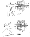
- the dowel shown in FIG. 1 consists of an expansion part, generally designated 1, and a counter bearing, generally designated 2.
- the expansion part 1 has two mutually opposite legs 3, which are connected to one another at one end via a bridge 4 provided with an internal thread.
- the Bridge 4 opposite end area protrude from the legs 3 two hook-like ring beads 5.
- the counter bearing 2 is made of plastic and is composed of a shaft 6 and a head-like shoulder 7 molded onto it.
- the free end of the shaft 6 carries two radially inwardly directed annular beads 8, with which the annular beads 5 of the expansion part 1 are hooked.
- the shaft 6 has 8 longitudinal slots 9 in the area of the annular beads. These cause the shaft section carrying the ring beads 8 to spring open when the expansion part 2 or its ring beads 5 enter.
- the dowel is inserted into receiving openings 11, 12 of a plate-shaped object 13 or a component 14 to be fastened, which cover one another for fastening purposes.
- the legs 3 protrude beyond the exposed side of the component 14.
- a mandrel 15 of a pulling device designated overall by 16, projects.
- a support tube 17 of the pulling device 16 bears against the end face of the annular beads 5 on the expansion part side.
- the pulling device 16 is actuated via its handle 18, as can be seen in FIG. 2.
- the mandrel 15 moves against the direction of insertion of the dowel - there is axial compression and radial widening of the legs 3.
- the latter lie against the exposed surface of the component 14 in this way.
- Further retraction of the mandrel 15 causes the object 13 to be clamped together the component 14 in cooperation with the shoulder 7 with the flared legs 3.
- the pulling device 16 with the pulling pin 15 is then removed from the dowel.
Claims (4)
Priority Applications (1)
| Application Number | Priority Date | Filing Date | Title |
|---|---|---|---|
| AT83102272T ATE20271T1 (de) | 1982-03-09 | 1983-03-08 | Duebel zum befestigen von gegenstaenden an bauteilen. |
Applications Claiming Priority (2)
| Application Number | Priority Date | Filing Date | Title |
|---|---|---|---|
| DE3208461 | 1982-03-09 | ||
| DE19823208461 DE3208461A1 (de) | 1982-03-09 | 1982-03-09 | "duebel zum befestigen von gegenstaenden an bauteilen" |
Publications (2)
| Publication Number | Publication Date |
|---|---|
| EP0088434A1 EP0088434A1 (fr) | 1983-09-14 |
| EP0088434B1 true EP0088434B1 (fr) | 1986-06-04 |
Family
ID=6157737
Family Applications (1)
| Application Number | Title | Priority Date | Filing Date |
|---|---|---|---|
| EP83102272A Expired EP0088434B1 (fr) | 1982-03-09 | 1983-03-08 | Cheville pour la fixation des objets à des éléments de construction |
Country Status (3)
| Country | Link |
|---|---|
| EP (1) | EP0088434B1 (fr) |
| AT (1) | ATE20271T1 (fr) |
| DE (1) | DE3208461A1 (fr) |
Families Citing this family (2)
| Publication number | Priority date | Publication date | Assignee | Title |
|---|---|---|---|---|
| FR2736001B1 (fr) * | 1995-06-30 | 1997-09-26 | Otalu Sa Soc | Appareil de pose pour le poinconnage et le sertissage en aveugle d'un ecrou noye a fut hexagonal |
| US6935821B2 (en) * | 2002-04-05 | 2005-08-30 | Illinois Tool Works, Inc. | Mushrooming expandable anchor |
Citations (1)
| Publication number | Priority date | Publication date | Assignee | Title |
|---|---|---|---|---|
| DE3017801A1 (de) * | 1979-05-11 | 1980-11-20 | Lloyd Sylvester Binns | Blindnietvorrichtung |
Family Cites Families (12)
| Publication number | Priority date | Publication date | Assignee | Title |
|---|---|---|---|---|
| DE7412185U (de) * | 1974-07-25 | Raymond A | Blindniet | |
| DE7700578U1 (fr) * | Futters (London) Ltd., London | |||
| US2236079A (en) * | 1940-02-23 | 1941-03-25 | Mone B Call | Wall bolt |
| DE822010C (de) * | 1950-05-12 | 1951-11-22 | Langensiepen Kg M | Wandanker |
| DE1926515U (de) * | 1962-08-16 | 1965-11-04 | Artur Fischer | Vorrichtung zum verbinden von bauteilen. |
| FR1411180A (fr) * | 1964-08-05 | 1965-09-17 | Anciens Ets Bac | Perfectionnements aux écrous aveugles et analogues |
| GB1158907A (en) * | 1965-11-30 | 1969-07-23 | Avdel Ltd | Blind Hole Anchor Nut Fastener Device |
| US4075924A (en) * | 1976-05-14 | 1978-02-28 | Mechanical Plastics Corporation | Anchor assembly for fastener |
| FR2371597A1 (fr) * | 1976-11-23 | 1978-06-16 | Bassan Et Co Sa | Dispositif de fixation |
| GB1603241A (en) * | 1978-05-11 | 1981-11-18 | Linread Ltd | Rivet and method of riveting |
| ES244708Y (es) * | 1979-07-23 | 1980-04-16 | Taco-remache perfeccionado para la sujecion entre si de pa- neles y similares | |
| DE3035867A1 (de) * | 1979-09-28 | 1981-04-16 | Aerpat Ag, Zug | Selbstverstopfender blindniet |
-
1982
- 1982-03-09 DE DE19823208461 patent/DE3208461A1/de active Granted
-
1983
- 1983-03-08 AT AT83102272T patent/ATE20271T1/de not_active IP Right Cessation
- 1983-03-08 EP EP83102272A patent/EP0088434B1/fr not_active Expired
Patent Citations (1)
| Publication number | Priority date | Publication date | Assignee | Title |
|---|---|---|---|---|
| DE3017801A1 (de) * | 1979-05-11 | 1980-11-20 | Lloyd Sylvester Binns | Blindnietvorrichtung |
Also Published As
| Publication number | Publication date |
|---|---|
| DE3208461C2 (fr) | 1990-10-18 |
| DE3208461A1 (de) | 1983-09-15 |
| ATE20271T1 (de) | 1986-06-15 |
| EP0088434A1 (fr) | 1983-09-14 |
Similar Documents
| Publication | Publication Date | Title |
|---|---|---|
| DE6925101U (de) | Zweiteiliges verbindungselement | |
| DE1400846B2 (de) | Steckbuchse | |
| DE102010002847A1 (de) | Blindniet mit einem Nietkörper aus Kunststoff | |
| DE2606498A1 (de) | Befestigungsmittel | |
| DE3730353A1 (de) | Verfahren zum verankern eines spreizduebels | |
| EP0088434B1 (fr) | Cheville pour la fixation des objets à des éléments de construction | |
| EP0209485B1 (fr) | Cheville à expansion | |
| DE4239465C2 (de) | Verfahren zum Verbinden zweier übereinanderliegender flacher dünner Objekte | |
| DE2849140A1 (de) | Spreizduebel zur abstandsbefestigung von verkleidungselementen o.dgl. | |
| DE6601294U (fr) | ||
| EP0279936B1 (fr) | Chevilles avec douilles à expansion | |
| DE2339306B1 (de) | Blindniet | |
| EP0392051B1 (fr) | Procédé et dispositif pour attacher une broche de centrage | |
| DE6948952U (de) | Selbstbohrender blindniet | |
| DD267536A5 (de) | Duebel mit spreizhuelse | |
| DE20303806U1 (de) | Spreizanker aus Metall | |
| DE2932055A1 (de) | Verfahren und vorrichtung zum positionieren und aufweiten von rohren | |
| DE6930966U (de) | Muffenrohrdichtung aus elastischem material | |
| DE102013110983A1 (de) | Verbindungssystem | |
| EP0227595B1 (fr) | Cheville à expansion | |
| DE8022728U1 (de) | Widerlager fuer ein nietwerkzeug | |
| DE1814499B2 (de) | Spanndübel, insbesondere zum Tragen von Heizkörpern | |
| DE601441C (de) | Rohrverbindung bzw. Kupplung, insbesondere fuer Rohre aus weichem Metall | |
| AT205953B (de) | Starre Verbindung für stumpf gegeneinanderstoßende Segmente des bogen- oder- ringförmigen Ausbaues, insbesondere für Strecken im Bergbau | |
| DE2408892A1 (de) | Schlauchverbinder |
Legal Events
| Date | Code | Title | Description |
|---|---|---|---|
| PUAI | Public reference made under article 153(3) epc to a published international application that has entered the european phase |
Free format text: ORIGINAL CODE: 0009012 |
|
| AK | Designated contracting states |
Designated state(s): AT CH FR GB LI NL SE |
|
| 17P | Request for examination filed |
Effective date: 19831011 |
|
| GRAA | (expected) grant |
Free format text: ORIGINAL CODE: 0009210 |
|
| AK | Designated contracting states |
Kind code of ref document: B1 Designated state(s): AT CH FR GB LI NL SE |
|
| REF | Corresponds to: |
Ref document number: 20271 Country of ref document: AT Date of ref document: 19860615 Kind code of ref document: T |
|
| ET | Fr: translation filed | ||
| PLBE | No opposition filed within time limit |
Free format text: ORIGINAL CODE: 0009261 |
|
| STAA | Information on the status of an ep patent application or granted ep patent |
Free format text: STATUS: NO OPPOSITION FILED WITHIN TIME LIMIT |
|
| 26N | No opposition filed | ||
| REG | Reference to a national code |
Ref country code: FR Ref legal event code: ST |
|
| EAL | Se: european patent in force in sweden |
Ref document number: 83102272.8 |
|
| PGFP | Annual fee paid to national office [announced via postgrant information from national office to epo] |
Ref country code: SE Payment date: 19950221 Year of fee payment: 13 |
|
| PGFP | Annual fee paid to national office [announced via postgrant information from national office to epo] |
Ref country code: GB Payment date: 19950224 Year of fee payment: 13 Ref country code: AT Payment date: 19950224 Year of fee payment: 13 |
|
| PGFP | Annual fee paid to national office [announced via postgrant information from national office to epo] |
Ref country code: FR Payment date: 19950227 Year of fee payment: 13 |
|
| PGFP | Annual fee paid to national office [announced via postgrant information from national office to epo] |
Ref country code: NL Payment date: 19950331 Year of fee payment: 13 |
|
| PGFP | Annual fee paid to national office [announced via postgrant information from national office to epo] |
Ref country code: CH Payment date: 19950519 Year of fee payment: 13 |
|
| PG25 | Lapsed in a contracting state [announced via postgrant information from national office to epo] |
Ref country code: GB Effective date: 19960308 Ref country code: AT Effective date: 19960308 |
|
| PG25 | Lapsed in a contracting state [announced via postgrant information from national office to epo] |
Ref country code: SE Effective date: 19960309 |
|
| PG25 | Lapsed in a contracting state [announced via postgrant information from national office to epo] |
Ref country code: LI Effective date: 19960331 Ref country code: CH Effective date: 19960331 |
|
| PG25 | Lapsed in a contracting state [announced via postgrant information from national office to epo] |
Ref country code: NL Effective date: 19961001 |
|
| GBPC | Gb: european patent ceased through non-payment of renewal fee |
Effective date: 19960308 |
|
| REG | Reference to a national code |
Ref country code: CH Ref legal event code: PL |
|
| PG25 | Lapsed in a contracting state [announced via postgrant information from national office to epo] |
Ref country code: FR Effective date: 19961129 |
|
| NLV4 | Nl: lapsed or anulled due to non-payment of the annual fee |
Effective date: 19961001 |
|
| EUG | Se: european patent has lapsed |
Ref document number: 83102272.8 |
|
| REG | Reference to a national code |
Ref country code: FR Ref legal event code: ST |