EP0088434B1 - Dowel for fastening objects to construction elements - Google Patents
Dowel for fastening objects to construction elements Download PDFInfo
- Publication number
- EP0088434B1 EP0088434B1 EP83102272A EP83102272A EP0088434B1 EP 0088434 B1 EP0088434 B1 EP 0088434B1 EP 83102272 A EP83102272 A EP 83102272A EP 83102272 A EP83102272 A EP 83102272A EP 0088434 B1 EP0088434 B1 EP 0088434B1
- Authority
- EP
- European Patent Office
- Prior art keywords
- dowel
- expansion part
- shaft
- abutment
- fastened
- Prior art date
- Legal status (The legal status is an assumption and is not a legal conclusion. Google has not performed a legal analysis and makes no representation as to the accuracy of the status listed.)
- Expired
Links
- 238000010276 construction Methods 0.000 title 1
- 230000006835 compression Effects 0.000 claims abstract description 6
- 238000007906 compression Methods 0.000 claims abstract description 6
- 230000000149 penetrating effect Effects 0.000 claims abstract 2
- 239000011324 bead Substances 0.000 claims description 15
- 238000003780 insertion Methods 0.000 description 5
- 230000037431 insertion Effects 0.000 description 5
- 238000000034 method Methods 0.000 description 3
- 239000000725 suspension Substances 0.000 description 1
Images
Classifications
-
- F—MECHANICAL ENGINEERING; LIGHTING; HEATING; WEAPONS; BLASTING
- F16—ENGINEERING ELEMENTS AND UNITS; GENERAL MEASURES FOR PRODUCING AND MAINTAINING EFFECTIVE FUNCTIONING OF MACHINES OR INSTALLATIONS; THERMAL INSULATION IN GENERAL
- F16B—DEVICES FOR FASTENING OR SECURING CONSTRUCTIONAL ELEMENTS OR MACHINE PARTS TOGETHER, e.g. NAILS, BOLTS, CIRCLIPS, CLAMPS, CLIPS OR WEDGES; JOINTS OR JOINTING
- F16B13/00—Dowels or other devices fastened in walls or the like by inserting them in holes made therein for that purpose
- F16B13/04—Dowels or other devices fastened in walls or the like by inserting them in holes made therein for that purpose with parts gripping in the hole or behind the reverse side of the wall after inserting from the front
- F16B13/06—Dowels or other devices fastened in walls or the like by inserting them in holes made therein for that purpose with parts gripping in the hole or behind the reverse side of the wall after inserting from the front combined with expanding sleeve
- F16B13/061—Dowels or other devices fastened in walls or the like by inserting them in holes made therein for that purpose with parts gripping in the hole or behind the reverse side of the wall after inserting from the front combined with expanding sleeve of the buckling type
-
- B—PERFORMING OPERATIONS; TRANSPORTING
- B25—HAND TOOLS; PORTABLE POWER-DRIVEN TOOLS; MANIPULATORS
- B25B—TOOLS OR BENCH DEVICES NOT OTHERWISE PROVIDED FOR, FOR FASTENING, CONNECTING, DISENGAGING OR HOLDING
- B25B27/00—Hand tools, specially adapted for fitting together or separating parts or objects whether or not involving some deformation, not otherwise provided for
- B25B27/0007—Tools for fixing internally screw-threaded tubular fasteners
Landscapes
- Engineering & Computer Science (AREA)
- Mechanical Engineering (AREA)
- General Engineering & Computer Science (AREA)
- Furniture Connections (AREA)
- Joining Of Building Structures In Genera (AREA)
- Mutual Connection Of Rods And Tubes (AREA)
- Dowels (AREA)
Abstract
Description
Die Erfindung betrifft einen Dübel zum Befestigen von Gegenständen an Bauteilen, mit einem unter axialer Stauchung radial aufweitbaren Spreizteil und einem Gegenlager, das einen die zu befestigenden Gegenstände wenigstens teilweise durchsetzenden Schaft und eine den Schaft radial überragende, sich auf den zu befestigenden Gegenständen abstützende Schulter aufweist.The invention relates to a dowel for attaching objects to components, with an expanding part radially expandable under axial compression and a counter bearing which has a shaft which at least partially penetrates the objects to be fastened and a shoulder which projects radially beyond the shaft and is supported on the objects to be fastened .
Zum Befestigen plattenartiger Gegenstände an Bauteilen ist ein Dübel bekannt (DE-A-3017801), der aus einem hülsenförmigen Spreizteil und einem im wesentlichen rohrförmigen Gegenlager besteht, wobei das Spreizteil und das Gegenlager von einem diese zusammenhaltenden Zugdorn durchgriffen sind.For fastening plate-like objects to components, a dowel is known (DE-A-3017801), which consists of a sleeve-shaped expansion part and an essentially tubular counter bearing, the expansion part and the counter bearing being penetrated by a pulling mandrel which holds them together.
Für den Befestigungsvorgang wird der Dübel in sich deckende Aufnahmeöffnungen des zu befestigenden Gegenstandes bzw. Bauteiles eingeschoben, wobei sich eine als Kopf ausgebildete Schulter des Gegenlagers am zu befestigenden Gegenstand abstützt. Durch anschliessendes Zurückziehen des Zugdorns entgegen der Einführrichtung des Dübels, was mittels einer sich am Gegenlager abstützenden Zugvorrichtung erfolgt, wird das Spreizteil axial gestaucht und dadurch radial geweitet. Das geweitete Spreizteil legt sich gegen die ihm zugewandte Seite des Bauteils. Der am freien Ende des Spreizteils über einen Kopf angreifende Zugdorn wird in der zurückgezogenen Position axial arretiert. Hierzu dient ein sich schulterseitig abstützender Ring, der sich unter plastischer Verformung durch den Gegendruck der Zugvorrichtung in einen umlaufenden Einstich des Zugdorns einlegt.For the fastening process, the dowel is inserted into overlapping receiving openings of the object or component to be fastened, a shoulder of the counter bearing designed as a head being supported on the object to be fastened. By subsequently pulling back the pulling mandrel against the direction of insertion of the dowel, which is done by means of a pulling device supported on the counter bearing, the expansion part is axially compressed and thereby radially expanded. The widened expansion part lies against the side of the component facing it. The pulling mandrel, which acts on a head at the free end of the expanding part, is axially locked in the retracted position. For this purpose, a ring is supported on the shoulder, which is inserted into a circumferential recess of the mandrel under plastic deformation due to the counterpressure of the pulling device.
Ein erheblicher Nachteil dieses bekannten Dübels besteht darin, dass für unterschiedliche Befestigungsdicken nebst Gegenlager mit unterschiedlichen Baulängen auch unterschiedlich lange Zugdorne bereitgehalten werden müssen. Hinzu kommt ferner der Nachteil, dass der Zugdorn zur Beibehaltung der Befestigung stets im Spreizteil bzw. Gegenlager bleiben muss, so dass es grundsätzlich nicht möglich ist, diese Dübelart als sogenannten Innengewindedübel einzusetzen.A considerable disadvantage of this known dowel is that for different fastening thicknesses, in addition to counter bearings with different overall lengths, pulling mandrels of different lengths must also be kept ready. In addition, there is the disadvantage that the mandrel must always remain in the expansion part or counter bearing in order to retain the fastening, so that it is fundamentally not possible to use this type of dowel as a so-called internal thread dowel.
Der Erfindung liegt die Aufgabe zugrunde, einen Dübel zur hintergreifenden Befestigung zu schaffen, der sich durch einfachen Aufbau und Anpassbarkeit an unterschiedliche Befestigungsdicken auszeichnet.The invention has for its object to provide a dowel for engaging behind, which is characterized by simple structure and adaptability to different mounting thicknesses.
Erfindungsgemäss wird die Aufgabe dadurch gelöst, dass das Spreizteil und das Gegenlager über eine Zugkräfte aufnehmende, einfach lösbare Verbindungseinrichtung miteinander verbunden sind.According to the invention, the object is achieved in that the expansion part and the counter bearing are connected to one another via an easily detachable connecting device which absorbs tensile forces.
Die erfindungsgemässe Verbindungseinrichtung zwischen Spreizteil und Gegenlager hält diese Teile für das Einschieben derselben in die Aufnahmeöffnungen zu einer Einheit zusammen und nimmt die während sowie nach dem Befestigungsvorgang auftretenden Zugspannungen zwischen Spreizteil und Gegenlager auf. Zum Setzen des Dübels wird ein am einführrichtungsseitigen Ende des Spreizteils angreifender Zugdorn einer sich am Gegenlager abstützenden Zugvorrichtung entgegen der Einführrichtung des Dübels gezogen, so dass es durch axiale Stauchung zum radialen Weiten des Spreizteils und damit zur Anlage desselben am Bauteil unter Spannung kommt. Anschliessend wird der Zugdorn dem Dübel entnommen, worauf dieser beispielsweise auch zur Aufnahme einer Ankerstange geeignet ist.The connecting device according to the invention between the expansion part and the counterbearing holds these parts together for insertion into the receiving openings to form a unit and absorbs the tensile stresses that occur between the expansion part and the counterbearing during and after the fastening process. To set the dowel, a pulling mandrel engaging at the end of the expansion part on the insertion direction side of a pulling device supported on the thrust bearing is pulled against the insertion direction of the dowel, so that axial compression causes the expansion part to expand radially and thus to engage the component under tension. The mandrel is then removed from the dowel, whereupon it is also suitable for receiving an anchor rod, for example.
Zur Verwendung des Dübels für stark unterschiedliche Befestigungsdicken ist nur ein entsprechend langes Gegenlager bereitzuhalten bzw. mit dem Spreizteil in Verbindung zu bringen. Kleinere Unterschiede der Befestigungsdicke lassen sich durch unterschiedlich starkes axiales Stauchen des Spreizteils ausgleichen.To use the dowel for widely differing fastening thicknesses, only a correspondingly long counter bearing must be kept available or connected to the expansion part. Smaller differences in the fastening thickness can be compensated for by varying the axial compression of the expansion part.
Vorzugsweise ist die Verbindungseinrichtung an die einander benachbarten Endbereiche von Spreizteil und Gegenlager angeordnet. Auf diese Weise lässt sich ein einfacher, sicherer, den Weitungsvorgang des Spreizteils nicht hindernder Verbund von Spreizteil und Gegenlager erreichen.The connecting device is preferably arranged on the mutually adjacent end regions of the expansion part and counter bearing. In this way, a simple, reliable combination of the expansion part and the counter bearing, which does not prevent the expansion process of the expansion part, can be achieved.
Die Verbindungseinrichtung kann beispielsweise durch am Spreizteil und Gegenlager angreifende Bügel gebildet sein. Ebenso eignet sich hierzu ein Bajonetteingriff des Spreizteils in das Gegenlager. Als besonders vorteilhafte Ausbildungsform der Verbindungseinrichtung haben sich jedoch miteinander hakenartig verrastbare Ringwulste bewährt.The connecting device can be formed, for example, by brackets acting on the expansion part and counter bearing. A bayonet engagement of the expansion part in the counter bearing is also suitable for this. However, ring beads which can be locked together in a hook-like manner have proven useful as a particularly advantageous embodiment of the connecting device.
Da es sich als zweckmässig erwiesen hat, den Schaft des Gegenlagers grösser als den äusseren Ausgangsdurchmesser des Spreizteils zu halten, weisen die spreizteilseitigen Ringwulste zweckmässig radial nach aussen und verhaken sich so an korrespondierend nach innen gerichteten Ringwulsten des Gegenlagers. An den spreizteilseitigen, mit dem Gegenlager verhakten Ringwulsten kann sich das Gehäuse der Zugvorrichtung abstützen, während der geräteseitige Zugdorn das Spreizteil staucht.Since it has proven to be expedient to keep the shaft of the counter bearing larger than the outer starting diameter of the expanding part, the ring beads on the expanding part expediently point radially outward and thus hook on correspondingly inwardly directed ring beads of the counter bearing. The housing of the pulling device can be supported on the expansion beads on the side, hooked to the counter bearing, while the pulling mandrel on the device compresses the expansion part.
Nach einem weiteren Vorschlag der Erfindung sind zur radialen Federung im Bereich wenigstens eines der Ringwulste Längsschlitze vorgesehen. Auf diese Weise wird das Zusammenfügen von Spreizteil und Gegenlager vereinfacht, indem die Ringwulste nach dem Zusammenschieben der besagten Teile miteinander selbsttätig verrasten.According to a further proposal of the invention, longitudinal slots are provided for radial suspension in the region of at least one of the annular beads. In this way, the joining of the expansion part and the counterbearing is simplified by the ring beads automatically locking together after the said parts have been pushed together.
Die Erfindung wird nachstehend anhand einer Zeichnung, die ein Ausführungsbeispiel wiedergibt, näher erläutert. Es zeigen:
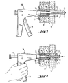
- Fig. 1 einen in Aufnahmeöffnungen eingeführten Dübel mit einer Zugvorrichtung, vor dem Aufweiten des Spreizteils,
- Fig. 2 den Dübel nach Fig. 1 mit der Zugvorrichtung, nach erfolgtem Aufweiten des Spreizteils.
- 1 shows a dowel inserted into receiving openings with a pulling device before the expansion part is expanded,
- Fig. 2 shows the dowel according to Fig. 1 with the pulling device after expansion of the expansion part.
Der in Fig. 1 dargestellte Dübel besteht aus einem insgesamt mit 1 bezeichneten Spreizteil und einem insgesamt mit 2 bezeichneten Gegenlager.The dowel shown in FIG. 1 consists of an expansion part, generally designated 1, and a counter bearing, generally designated 2.
Das Spreizteil 1 weist zwei einander gegenüberliegende Schenkel 3 auf, die über eine mit einem Innengewinde versehene Brücke 4 an einem Ende miteinander verbunden sind. In dem der Brücke 4 gegenüberliegenden Endbereich ragen von den Schenkeln 3 zwei hakenartige Ringwulste 5 ab.The expansion part 1 has two mutually
Das Gegenlager 2 besteht aus Kunststoff und setzt sich aus einem Schaft 6 sowie einer an diesen angeformten kopfartigen Schulter 7 zusammen. Das freie Ende des Schaftes 6 trägt zwei radial nach innen gerichtete Ringwulste 8, mit denen die Ringwulste 5 des Spreizteils 1 verhakt sind. Um das zur Verhakung führende Ineinanderschieben von Spreizteil 1 und Gegenlager 2 zu erleichtern, weist der Schaft 6 im Bereich der Ringwulste 8 Längsschlitze 9 auf. Diese bewirken ein elastisches Auffedern des die Ringwulste 8 tragenden Schaftabschnittes beim Eintritt des Spreizteils 2 bzw. dessen Ringwulste 5.The counter bearing 2 is made of plastic and is composed of a shaft 6 and a head-
Der Dübel wird, wie die Fig. 1 zeigt, zum Befestigungszwecke in sich deckende Aufnahmeöffnungen 11, 12 eines zu befestigenden plattenförmigen Gegenstandes 13 bzw. eines Bauteils 14 eingeführt. Die Schenkel 3 überragen dabei die freiliegende Seite des Bauteils 14. In die Brücke 4 bzw. deren Innengewinde ragt ein Zugdorn 15 einer insgesamt mit 16 bezeichneten Zugvorrichtung. Ein Stützrohr 17 der Zugvorrichtung 16 legt sich gegen die Stirnseite der spreizteilseitigen Ringwulste 5 an.As shown in FIG. 1, the dowel is inserted into receiving
Zur Erzielung der Befestigung wird die Zugvorrichtung 16 über deren Handgriff 18, wie der Fig. 2 entnehmbar ist, betätigt. Dadurch verschiebt sich der Zugdorn 15 entgegen der Einführrichtung des Dübels - es kommt zur axialen Stauchung und radialen Weitung der Schenkel 3. Letztere legen sich auf diese Weise gegen die freiliegende Fläche des Bauteils 14. Weiteres Einziehen des Zugdorns 15 bewirkt ein Zusammenspannen des Gegenstandes 13 mit dem Bauteil 14 unter Zusammenwirkung der Schulter 7 mit den aufgeweiteten Schenkeln 3. Die Zugvorrichtung 16 mit dem Zugdorn 15 wird anschliessend vom Dübel entnommen.To achieve the attachment, the
Claims (4)
Priority Applications (1)
| Application Number | Priority Date | Filing Date | Title |
|---|---|---|---|
| AT83102272T ATE20271T1 (en) | 1982-03-09 | 1983-03-08 | DOWELS FOR ATTACHING OBJECTS TO COMPONENTS. |
Applications Claiming Priority (2)
| Application Number | Priority Date | Filing Date | Title |
|---|---|---|---|
| DE19823208461 DE3208461A1 (en) | 1982-03-09 | 1982-03-09 | "DOWEL FOR ATTACHING OBJECTS TO COMPONENTS" |
| DE3208461 | 1982-03-09 |
Publications (2)
| Publication Number | Publication Date |
|---|---|
| EP0088434A1 EP0088434A1 (en) | 1983-09-14 |
| EP0088434B1 true EP0088434B1 (en) | 1986-06-04 |
Family
ID=6157737
Family Applications (1)
| Application Number | Title | Priority Date | Filing Date |
|---|---|---|---|
| EP83102272A Expired EP0088434B1 (en) | 1982-03-09 | 1983-03-08 | Dowel for fastening objects to construction elements |
Country Status (3)
| Country | Link |
|---|---|
| EP (1) | EP0088434B1 (en) |
| AT (1) | ATE20271T1 (en) |
| DE (1) | DE3208461A1 (en) |
Families Citing this family (2)
| Publication number | Priority date | Publication date | Assignee | Title |
|---|---|---|---|---|
| FR2736001B1 (en) * | 1995-06-30 | 1997-09-26 | Otalu Sa Soc | LAYING APPARATUS FOR BLIND PUNCHING AND BLINDING OF A WASTE HEXAGONAL NUT |
| US6935821B2 (en) * | 2002-04-05 | 2005-08-30 | Illinois Tool Works, Inc. | Mushrooming expandable anchor |
Citations (1)
| Publication number | Priority date | Publication date | Assignee | Title |
|---|---|---|---|---|
| DE3017801A1 (en) * | 1979-05-11 | 1980-11-20 | Lloyd Sylvester Binns | BLIND RIVET DEVICE |
Family Cites Families (12)
| Publication number | Priority date | Publication date | Assignee | Title |
|---|---|---|---|---|
| DE7700578U1 (en) * | Futters (London) Ltd., London | |||
| DE7412185U (en) * | 1974-07-25 | Raymond A | Blind rivet | |
| US2236079A (en) * | 1940-02-23 | 1941-03-25 | Mone B Call | Wall bolt |
| DE822010C (en) * | 1950-05-12 | 1951-11-22 | Langensiepen Kg M | Wall anchor |
| DE1926515U (en) * | 1962-08-16 | 1965-11-04 | Artur Fischer | DEVICE FOR CONNECTING COMPONENTS. |
| FR1411180A (en) * | 1964-08-05 | 1965-09-17 | Anciens Ets Bac | Improvements to blind nuts and the like |
| GB1158907A (en) * | 1965-11-30 | 1969-07-23 | Avdel Ltd | Blind Hole Anchor Nut Fastener Device |
| US4075924A (en) * | 1976-05-14 | 1978-02-28 | Mechanical Plastics Corporation | Anchor assembly for fastener |
| FR2371597A1 (en) * | 1976-11-23 | 1978-06-16 | Bassan Et Co Sa | Expanding dowel for attaching objects to thin walls - has longitudinal slots to permit radial deformation when dowel bows outward |
| GB1603241A (en) * | 1978-05-11 | 1981-11-18 | Linread Ltd | Rivet and method of riveting |
| ES244708Y (en) * | 1979-07-23 | 1980-04-16 | TACO-RIVET PERFECTED FOR FASTENING BETWEEN YES OF PANELS AND THE LIKE | |
| DE3035867A1 (en) * | 1979-09-28 | 1981-04-16 | Aerpat Ag, Zug | SELF-CLOGGING RIVET |
-
1982
- 1982-03-09 DE DE19823208461 patent/DE3208461A1/en active Granted
-
1983
- 1983-03-08 AT AT83102272T patent/ATE20271T1/en not_active IP Right Cessation
- 1983-03-08 EP EP83102272A patent/EP0088434B1/en not_active Expired
Patent Citations (1)
| Publication number | Priority date | Publication date | Assignee | Title |
|---|---|---|---|---|
| DE3017801A1 (en) * | 1979-05-11 | 1980-11-20 | Lloyd Sylvester Binns | BLIND RIVET DEVICE |
Also Published As
| Publication number | Publication date |
|---|---|
| DE3208461C2 (en) | 1990-10-18 |
| DE3208461A1 (en) | 1983-09-15 |
| EP0088434A1 (en) | 1983-09-14 |
| ATE20271T1 (en) | 1986-06-15 |
Similar Documents
| Publication | Publication Date | Title |
|---|---|---|
| DE6925101U (en) | TWO-PIECE FASTENER | |
| DE1400846B2 (en) | SOCKET | |
| DE102010002847A1 (en) | Blind rivet with a plastic rivet body | |
| DE2606498A1 (en) | FASTENERS | |
| DE3730353A1 (en) | METHOD FOR ANCHORING A SPREADING DOWEL | |
| EP0088434B1 (en) | Dowel for fastening objects to construction elements | |
| EP0209485B1 (en) | Expansible anchor | |
| DE4239465C2 (en) | Method for connecting two superimposed flat thin objects | |
| DE2849140A1 (en) | SPREADING DOWEL FOR THE FASTENING OF CLADDING ELEMENTS OR THE LIKE. | |
| DE6601294U (en) | ||
| EP0279936B1 (en) | Dowel with an expansion sleeve | |
| DE2339306B1 (en) | Blind rivet | |
| EP0392051B1 (en) | Process and arrangement for fastening an alignment pin | |
| DE6948952U (en) | SELF-DRILLING BLIND RIVET | |
| DD267536A5 (en) | DUEBEL WITH SPREIZHUELSE | |
| DE20303806U1 (en) | Expansion anchor made of metal | |
| DE2932055A1 (en) | METHOD AND DEVICE FOR POSITIONING AND EXPANDING TUBES | |
| DE6930966U (en) | SLEEVE PIPE SEAL MADE OF ELASTIC MATERIAL | |
| DE102013110983A1 (en) | connection system | |
| EP0227595B1 (en) | Expansion dowel | |
| DE8022728U1 (en) | RETIREMENT FOR A RIVETING TOOL | |
| DE1814499B2 (en) | Clamping dowels, in particular for carrying radiators | |
| DE601441C (en) | Pipe connection or coupling, especially for pipes made of soft metal | |
| AT205953B (en) | Rigid connection for butt against each other segments of the arched or ring-shaped expansion, especially for routes in mining | |
| DE2408892A1 (en) | Connector for flexible walled hoses - conically divergent plug is inserted in hose bore and secured by outer sleeve |
Legal Events
| Date | Code | Title | Description |
|---|---|---|---|
| PUAI | Public reference made under article 153(3) epc to a published international application that has entered the european phase |
Free format text: ORIGINAL CODE: 0009012 |
|
| AK | Designated contracting states |
Designated state(s): AT CH FR GB LI NL SE |
|
| 17P | Request for examination filed |
Effective date: 19831011 |
|
| GRAA | (expected) grant |
Free format text: ORIGINAL CODE: 0009210 |
|
| AK | Designated contracting states |
Kind code of ref document: B1 Designated state(s): AT CH FR GB LI NL SE |
|
| REF | Corresponds to: |
Ref document number: 20271 Country of ref document: AT Date of ref document: 19860615 Kind code of ref document: T |
|
| ET | Fr: translation filed | ||
| PLBE | No opposition filed within time limit |
Free format text: ORIGINAL CODE: 0009261 |
|
| STAA | Information on the status of an ep patent application or granted ep patent |
Free format text: STATUS: NO OPPOSITION FILED WITHIN TIME LIMIT |
|
| 26N | No opposition filed | ||
| REG | Reference to a national code |
Ref country code: FR Ref legal event code: ST |
|
| EAL | Se: european patent in force in sweden |
Ref document number: 83102272.8 |
|
| PGFP | Annual fee paid to national office [announced via postgrant information from national office to epo] |
Ref country code: SE Payment date: 19950221 Year of fee payment: 13 |
|
| PGFP | Annual fee paid to national office [announced via postgrant information from national office to epo] |
Ref country code: GB Payment date: 19950224 Year of fee payment: 13 Ref country code: AT Payment date: 19950224 Year of fee payment: 13 |
|
| PGFP | Annual fee paid to national office [announced via postgrant information from national office to epo] |
Ref country code: FR Payment date: 19950227 Year of fee payment: 13 |
|
| PGFP | Annual fee paid to national office [announced via postgrant information from national office to epo] |
Ref country code: NL Payment date: 19950331 Year of fee payment: 13 |
|
| PGFP | Annual fee paid to national office [announced via postgrant information from national office to epo] |
Ref country code: CH Payment date: 19950519 Year of fee payment: 13 |
|
| PG25 | Lapsed in a contracting state [announced via postgrant information from national office to epo] |
Ref country code: GB Effective date: 19960308 Ref country code: AT Effective date: 19960308 |
|
| PG25 | Lapsed in a contracting state [announced via postgrant information from national office to epo] |
Ref country code: SE Effective date: 19960309 |
|
| PG25 | Lapsed in a contracting state [announced via postgrant information from national office to epo] |
Ref country code: LI Effective date: 19960331 Ref country code: CH Effective date: 19960331 |
|
| PG25 | Lapsed in a contracting state [announced via postgrant information from national office to epo] |
Ref country code: NL Effective date: 19961001 |
|
| GBPC | Gb: european patent ceased through non-payment of renewal fee |
Effective date: 19960308 |
|
| REG | Reference to a national code |
Ref country code: CH Ref legal event code: PL |
|
| PG25 | Lapsed in a contracting state [announced via postgrant information from national office to epo] |
Ref country code: FR Effective date: 19961129 |
|
| NLV4 | Nl: lapsed or anulled due to non-payment of the annual fee |
Effective date: 19961001 |
|
| EUG | Se: european patent has lapsed |
Ref document number: 83102272.8 |
|
| REG | Reference to a national code |
Ref country code: FR Ref legal event code: ST |