EP0088430B1 - Finne für ein Windsurfbrett - Google Patents
Finne für ein Windsurfbrett Download PDFInfo
- Publication number
- EP0088430B1 EP0088430B1 EP83102267A EP83102267A EP0088430B1 EP 0088430 B1 EP0088430 B1 EP 0088430B1 EP 83102267 A EP83102267 A EP 83102267A EP 83102267 A EP83102267 A EP 83102267A EP 0088430 B1 EP0088430 B1 EP 0088430B1
- Authority
- EP
- European Patent Office
- Prior art keywords
- fin
- box
- fin according
- legs
- bore
- Prior art date
- Legal status (The legal status is an assumption and is not a legal conclusion. Google has not performed a legal analysis and makes no representation as to the accuracy of the status listed.)
- Expired
Links
Images

Classifications
-
- B—PERFORMING OPERATIONS; TRANSPORTING
- B63—SHIPS OR OTHER WATERBORNE VESSELS; RELATED EQUIPMENT
- B63B—SHIPS OR OTHER WATERBORNE VESSELS; EQUIPMENT FOR SHIPPING
- B63B32/00—Water sports boards; Accessories therefor
- B63B32/60—Board appendages, e.g. fins, hydrofoils or centre boards
- B63B32/64—Adjustable, e.g. by adding sections, by removing sections or by changing orientation or profile
Definitions
- the invention relates to a fin for a windsurf board, which is pivotally mounted about an axis in a fin box connected to the windsurf board, the pivot position being ascertainable in various intermediate positions by a resilient latching device, and the pivot point of the fin being arranged in the fin box which is open at the bottom is.
- a fin of this type was proposed for the first time for windsurfing according to an earlier proposal by the applicant (DE-U 7732145).
- this known fin which is generally referred to as a folding fin
- the aim is to make it possible to adjust the fin with regard to the different speeds at which fins of different lengths would be optimal.
- folding down the known fin the possibilities of injury during handling and damage to the fin during base runs are to be avoided.
- the invention has for its object to provide a fin of the type specified above, which when a selectable load, be it from ground contact or body contact, detaches itself from the fin box and therefore no longer presents any risk of injury or damage.
- This object is essentially achieved in a fin of the type specified above in that the axis is formed by two axle stubs projecting laterally from the fin, and in that each axle stub is held in the fin box by a releasable coupling device which, when one or both end positions are exceeded Axle stub releases.
- a coupling device is formed by a spring element, which is mounted in the fin box, the spring element holding the stub shaft with partial positive locking.
- This embodiment is particularly robust and simple, the force exerted on the stub axle being overcome to pull out or separate the fin from the fin box.
- the invention can be further developed in that the spring element is T-shaped with a cross piece and a foot directed downwards, the cross piece being mounted in front of and behind the stub axle in the fin box, that the foot has a slot open at the bottom and a has the stub receiving bore in connection with the slot, and that the slot forms two legs of the foot, the springs of which releases the stub from the bore.
- This embodiment of the spring element represents a simple and reliable form of coupling device which holds the fin securely under normal stresses and yet ensures that the axle stub can be released from its bearing when such stresses are exceeded.
- the slots in the spring elements are flared or funnel-shaped.
- the ends of the crossbar are held biased by additional spring elements against an upper wall of a bearing recess in the sword case.
- the spring elements can be coil springs, disc springs, rubber pads or the like.
- this device for adjusting the spring force of the spring elements exerted on the crosspiece.
- this device can be designed as adjustable screws in threads in the fin box, the ends of which engage with the spring elements.
- the threads are made of metal.
- the spring element described can preferably be embodied as a plastic part, in which case a to improve the suspension properties above the bore for the stub axles is provided with a continuation of the slot in connection relief opening.
- rounded relief notches can be provided at the transition between the crosspiece and the foot part.
- This configuration of the T-shaped spring element improves its suspension properties and at the same time prevents damage to the spring element itself.
- this configuration allows spring elements of sufficient width to be used with the necessary spring properties in order to ensure secure mounting of the stub axles.
- securing clips are provided on the spring elements or T-pieces, which hold the T-pieces in the bearing recesses.
- the securing brackets consist of a spring steel wire with a round cross section.
- the safety brackets consist essentially of U-shaped pieces with two legs and a connecting section, the two legs abutting the legs of the foot of the T-piece and the connecting section is cranked to the side and runs parallel to the crossbar at the top of the foot .
- the additional advantage is achieved that the spring force exerted on the stub axle of the T-piece can be significantly higher than is possible with a plastic part. This ensures with the simplest design that the fin is only triggered when it really encounters a serious obstacle.
- the securing bracket with respect to the fin In order to facilitate the insertion of the fin into the spring elements, it is preferred to design the securing bracket with respect to the fin to be pivotable laterally around the connecting section between an open and a closed position. In the open position, therefore, only the spring force of the spring element, which is preferably made of a plastic part, has to be overcome, while in the closed position, a much higher spring force is exerted on the stub axles.
- a particularly simple embodiment of the invention can be created in that the legs of the securing bracket have a bend in the plane parallel to the fin, the angle of which is such that the section lying below the bend in the closed position of the securing bracket rests parallel to the side of the fin .
- the securing bracket with a catch section for the stub axles, the catch section being designed as a hook-shaped extension of one of the legs which protrudes beyond the underside of the fin box.
- the hook-shaped extension serves as a handle for pivoting the safety bracket in the lateral direction.
- the free end of the extension is at a greater distance from the underside of the fin box than it corresponds to the diameter of the stub axle.
- the round cross section of the securing bracket With increasing pressure on the fin after the stub axles have moved into the catching section, the round cross section of the securing bracket is brought into the open position as a cam surface for pivoting the securing bracket, so that when this pressure is overcome the fin is completely released from the fin box.
- the fin it is particularly preferred to connect the fin to the fin box by means of a lanyard so that it is not lost when overloaded.
- a round rubber which is fastened in the region of the front edge of the section of the fin accommodated by the fin box and is guided through a bore in the fin to the rear edge of the section.
- the safety line should preferably be routed along one of the rear edges of the fin section to an anchor in the area of the lower edge of the fin box.
- This configuration in particular in connection with a round rubber as a safety line, allows the fin itself to be held simultaneously with a slight pretension with regard to a pivoting movement, so that the selected pivoting position of the fin is reliably maintained.
- the section of the fin accommodated by the fin box is designed with an approximately semicircular upper edge and with at least one rounded hump on the upper edge, which can optionally be brought into engagement with corresponding humps in the upper wall of the fin box.
- This configuration allows the fin to be securely locked in the selected position, which is possible without additional locking means or spring means due to the resilient configuration of the coupling devices.
- two bumps on the fin receive a bump of the fin box between them in the locked position.
- flanks of the first and last peaks of the fin box facing the fin are preferred. This makes it easier to trigger the fin.
- a locking device is additionally provided for the spring elements, which rigidly presses the transverse web of the T-piece 21 against the upper wall of the bearing recess.
- the locking device can be designed in detail by locking screws that can be screwed into the fin box.
- the locking screws can be screwed into the threaded inserts of the fin box instead of the set screws.
- a particularly preferred development of the invention can be created in that the set screws are designed as hollow screws with an internal thread and the locking screws engage in the internal thread. This embodiment makes it possible to choose both modes of operation of the fin in a compact design.
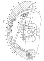
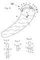
- FIG. 1 shows here only the section of the fin 3 which is received by the fin box 2 and which is shown in more detail in FIG. 5.
- the head section 4 of the fin 3 illustrated in FIG. 1 is essentially semicircular and has two bumps 5, 6 in its upper edge. The bumps protrude beyond the radius of the semicircular section 4.
- two stub axles 7, 8 are provided on the fin 3, which can also be formed as a continuous axis in a bore in the fin 3.
- the top wall 9 is in a region which corresponds to the region within which the fin 3 can be adjusted in different positions, with corresponding inward bumps 9, 10, 11, 12, 13 , 14, between which recesses 15, 16, 17, 18, 19 are formed, in which the bumps 5, 6 can engage in a form-fitting manner in the different positions of the fin 3.
- the stub axles 7 and 8 are held on both sides of the fin 3 in a coupling device, generally designated 20, in the fin box 2.
- the coupling device 20 serves to make it possible to move the fin 3 completely out of the fin box 2, should a force act upon the fin 3 when it comes into contact with the ground or when it falls, which tries to push the bumps 5 and 6 in the upper edge of the section 4 to move beyond one of the end positions, as defined by the recess 15 or 19 in the top wall 9 of the fin box 2.
- a coupling device 20 consists of a spring element 21, which is T-shaped with a transverse web 22 and a downward foot 23.
- the spring element is mounted in the bearing recesses 24 provided on both sides of the fin 3 in the fin box 2 by the crossbar 22 being pressed against an upper wall 27 of the bearing recess by further spring elements 25, 26.
- the further spring elements 25, 26 can be designed either as a coil spring or as a rubber cushion.
- each spring element 21 has a bore 28 which is connected to a slot 29 at the top and bottom. Ends above the bore 28 the slot 29 in a comparatively large relief bore 30. Below the bore 28, the slot 29 is flared or funnel-shaped.
- relief notches 31, 32 are provided on both sides of the spring element. It is obvious that this shape of the spring element, similar to a clothespin, enables the legs 33, 34 formed on both sides of the slot 29 to be moved apart in a spring-like manner, in which case the stub axle 7 or 8 can be moved out of the bore 28.
- the suspension properties of the spring element 21 can be determined by appropriate design of the relief opening 30 or relief notches 31, 32.
- the mounting recesses for the spring elements 21 are provided in side housings 35, 36 of the fin box 2. 1 shows that the opening 38 of the bearing recess 24 leading to the underside 37 of the fin box 2 and thus to the bottom surface of the windsurfing board 1 is also funnel-shaped or conically widening downwards in order to enable the legs 33 and 34 to spring open.
- a safety line 38 is also provided, which connects the fin 3 to the fin box 2.
- the safety line 38 is formed by a round rubber 39 which has an anchoring 41 in the region of the front edge 40 of the head section 4 of the fin 3.
- the round rubber 39 is guided from the anchoring 41, which is arranged in a recess 43 in the front edge 40, through a bore 42 to the rear edge 44 of the head section 4.
- an opening 45 is also provided in the head section 4, which also serves to save the weight of the fin 3.
- the round rubber is guided downward in an open groove 46 and fastened to the lower edge of the fin box 2 in an anchorage, generally designated 47.
- the described guidance of the safety line 38 serves, on the one hand, to enable the various positions of the fin 3 in the fin box 2 by means of elasticity without hindrance and, on the other hand, to hold the fin with sufficient play when the fin is torn out, so that it no longer offers any risk of injury.
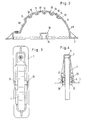
- FIG. 2 shows the fin box 2 in a lateral sectional view that is reduced compared to FIG. 1.
- the top wall 9 of the fin box 2 has a substantially semicircular shape, a rear wall section 48 having a radius which corresponds to the radius of the rear edge 44 corresponds to the head section 4. Furthermore, the tips of the inwardly directed cusps 10, 11, 12, 13 and 14 lie on this radius.
- a front wall section 49 of the wall 9 lies on the radius of the base of the depressions 15 to 19 formed between the bumps 10 to 14. This radius corresponds to the radius of a leading edge 50 (see FIG. 5) of the fin 3.
- the most forward bump 14 of the wall 9 is formed with a steep front flank, which forms a stop 51.
- a stop 52 engages with this stop, which through the transition edge from the radius of the rear edge 44 or front edge 40 of the head section 4 to the larger radius of the leading edge 50 is formed.
- This position represents the planned foremost or most vertical position of the fin 3 without triggering the coupling devices 20.
- Fig. 1 The most pivoted backward position of the fin 3 is illustrated in Fig. 1, in which the bumps 5, 6 sit in the recesses 18, 19.
- This position without triggering the coupling devices 20 is determined by striking the rear edge 53 against a stop 54 provided at the rear end of the fin box 2.
- the stop 54 forms part of the anchoring 47 of the suspension line and is preferably formed from a hard rubber or the like, so that the trailing edge can strike the stop 54 without damage.
- the swivel range of the fin 3 with respect to the fin box 2 is 20 89 ° without triggering the coupling devices.
- the coupling devices 20 also trigger on the fin 3 in the event of violent lateral impacts, in which case only one of the first Axle stub is moved down out of the coupling device.
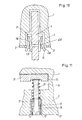
- FIGS. 9 to 11 The particularly preferred embodiment according to FIGS. 9 to 11 is described below, the basic structure of which corresponds to the embodiment according to the description above, so that the same reference numerals have been used for the same parts.
- a device is provided in order to adjust the spring force of the helical springs 25, 26 exerted on the transverse web 22 of the spring element 21.
- this device is designed as set screws 56, which can be screwed and unscrewed in metal inserts 57 in the fin box 2 in the direction of the crossbar.
- the free ends 58 of the set screws 56 are in engagement with the coil springs 25, 26, which sit with their opposite ends in recesses 59 in the crosspiece 22.
- each of the spring elements or T-pieces 21 is assigned a securing bracket 60, the function of which will be discussed in more detail with reference to FIG. 10.
- the safety bracket 60 is formed from a spring steel wire with a round cross-section essentially U-shaped.
- the securing bracket has two legs 61, 62 and a connecting section 63 connecting them.
- the two legs 61, 62 rest on the legs 33, 34 of the foot 23 and thus reinforce the spring force exerted by the legs 33, 34 on the stub axles 7, 8 of the fin 3, so that they only exert considerable pressure from the T- Be moved out.
- the connecting section 63 of the securing bracket 60 is cranked laterally and lies at the upper end of the foot 23 parallel to the crosspiece 22.
- the securing brackets 60 are designed to pivot laterally with respect to the fin 3 around the bent portion of the connecting section 63 between an open and a closed position.
- the legs 61, 62 have a bend 64 in the plane parallel to the fin 3, the angle of which is such that the section 65 of the legs 61, 62 lying below the bend 64 in the closed position of the securing bracket 60 parallel to the side of the fin 3 is present.
- the securing brackets 60 are provided with a catch section, generally designated 66, for the stub axles 7, 8, which in the exemplary embodiment shown consists of a hook-shaped extension 67 of the leg 61.
- the hook-shaped extension 67 protrudes over the underside 37 of the fin box 2 and at the same time forms a handle for the pivoting movement of the securing bracket 60 illustrated in FIG. 10.
- a distance is provided between the free end 68 of the hook-shaped extension 67 and the underside of the fin box 2, which is greater than the diameter of the stub axles 7 and 8. This allows the fin with its stub axles 7 and 8 into the area of the T-piece or spring element 21 are brought without the safety bracket 60 having to be pivoted into the open position.
- the fin 3 is moved out of the bearing while overcoming the spring force of the legs 33, 34 of the T-piece 21 and the spring force additionally exerted by the legs 61, 62, for example with light ground contact, the fin 3 is initially only partially triggered and held by the catch section 66 of the safety bracket. If the stress exerted on the fin 3 increases, the round cross section of the spring wire of the securing bracket 60 acts as a cam surface, so that the securing bracket is deflected laterally and the fin is completely detached from the fin box 2 and is only held on the windsurf board 1 by the rubber cord 38 becomes.
- the securing brackets 60 are then folded into the outwardly pivoted open position illustrated in FIG. 10, in which the legs 61, 62 do not have any additional spring force on the legs 33, 34 exercise. Consequently, when the fin 3 is inserted, only the substantially lower spring force of the legs 33, 34 has to be overcome.
- the two bumps 5, 6 receive one of the bumps 10, 11, 12 or 13 between them.
- the flanks 69, 70 of the last hump 14 or the first hump 71 on the fin box 2 are flatter than the flanks of the other humps.
- a particularly preferred embodiment of the locking device 72 is illustrated in an enlarged view in FIG. 11.
- the set screws 56 formed as hollow screws 75, which are provided with slots 76 for engagement with the screwdriver.
- the hollow screws 75 retain their function as set screws.
- the blocking screws 73 are dimensioned such that they can be screwed into an internal thread 77 provided in the hollow screws 75 and fit through the inside diameter of the coil springs 24 and 25, respectively.
- the anchor 47 for the rubber cord 38.
- the rubber cord 38 is provided at its end facing the anchoring 47 with a cable lug 79 or the like having a bore 78, the stop 54 for the trailing edge 53 of the fin 3 likewise being provided with a bore 80.
- the anchoring 47 is formed by a screw 81 which is passed through the bore 80 and the bore 78 into a threaded insert 82 made of metal provided in the fin box 2.
- the described embodiment ensures two basic functional principles of the fin 3, namely the adjustable grid system and the system blocked in the selected pivot position. In both systems, four different fin positions are possible for reasons of trimming and for safety, and at the same time, a total triggering of the fin is guaranteed in the event of overuse.
- the fin 3 folds back and forth due to the suspension in the event of unforeseen resistance, without jumping out of the T-piece 21.
- the fin 3 is only released from the bearing when the pressure does not drop.
- the spring mechanism is deactivated by the locking device 72, so that the fin jumps out of the bearing without any change in position and without any change in position.
- an easy assembly of the fin 3 is also possible if it should be carried separately for transport reasons, for example.
- the rubber cord 38 is first inserted into the groove 46 in the rear edge 44 of the head section 4 of the fin and the cable lug 79 located at the free end is threaded with its bore 78 onto the end of the screw 81, which previously passed through the bore 80 of the stop 54 has been.
- This arrangement is then screwed onto the fin box 2 by means of the screw 81 by screwing the screw 81 into the threaded insert 82.
- both safety clips 60 are pressed into the open, laterally pivoted-away position, and the fin 3 with its stub axles 7, 8 is pressed until it audibly snaps into place between the legs 33, 34 of the T-piece 21. Then both safety brackets 60 are pivoted into the closed position.
- the selected pivot position of the fin 3 can then optionally be fixed using the locking device 72.
Landscapes
- Chemical & Material Sciences (AREA)
- Engineering & Computer Science (AREA)
- Combustion & Propulsion (AREA)
- Mechanical Engineering (AREA)
- Ocean & Marine Engineering (AREA)
- Body Structure For Vehicles (AREA)
- Springs (AREA)
- Refuge Islands, Traffic Blockers, Or Guard Fence (AREA)
- Vibration Dampers (AREA)
Priority Applications (1)
| Application Number | Priority Date | Filing Date | Title |
|---|---|---|---|
| AT83102267T ATE20220T1 (de) | 1982-03-09 | 1983-03-08 | Finne fuer ein windsurfbrett. |
Applications Claiming Priority (4)
| Application Number | Priority Date | Filing Date | Title |
|---|---|---|---|
| DE3208466 | 1982-03-09 | ||
| DE3208466 | 1982-03-09 | ||
| DE19823221383 DE3221383A1 (de) | 1982-03-09 | 1982-06-05 | Finne fuer ein windsurfbrett |
| DE3221383 | 1982-06-05 |
Publications (3)
| Publication Number | Publication Date |
|---|---|
| EP0088430A2 EP0088430A2 (de) | 1983-09-14 |
| EP0088430A3 EP0088430A3 (en) | 1984-03-28 |
| EP0088430B1 true EP0088430B1 (de) | 1986-06-04 |
Family
ID=25800171
Family Applications (1)
| Application Number | Title | Priority Date | Filing Date |
|---|---|---|---|
| EP83102267A Expired EP0088430B1 (de) | 1982-03-09 | 1983-03-08 | Finne für ein Windsurfbrett |
Country Status (2)
| Country | Link |
|---|---|
| EP (1) | EP0088430B1 (enExample) |
| DE (1) | DE3221383A1 (enExample) |
Cited By (4)
| Publication number | Priority date | Publication date | Assignee | Title |
|---|---|---|---|---|
| WO1985004143A1 (fr) * | 1984-03-13 | 1985-09-26 | Hannes Marker | Planche a voile |
| EP0460438A3 (en) * | 1990-05-18 | 1992-03-18 | F2 International Gesellschaft M.B.H. | Fastening arrangement for a fin on a sailboard |
| GB2255937A (en) * | 1991-05-21 | 1992-11-25 | Andrew Thomas Kinnaird | Variable geometry wind surfer fin |
| WO2001070565A1 (en) * | 2000-03-22 | 2001-09-27 | Low Pressure Systems Pty Ltd. | Removable fin system |
Family Cites Families (7)
| Publication number | Priority date | Publication date | Assignee | Title |
|---|---|---|---|---|
| DE7830845U1 (de) * | 1979-03-29 | Schmid, Hermann, 8918 Diessen | Schwertkasten-System für Windsurfbrett | |
| CH603196A5 (enExample) * | 1976-10-22 | 1978-08-15 | Mistral Windsurfing Ag | |
| FR2376023A1 (fr) * | 1976-12-28 | 1978-07-28 | Ducruy Guy | Perfectionnements aux engins de navigation a voile |
| FR2461639A1 (fr) * | 1979-07-23 | 1981-02-06 | Tabur Marine | Derive mobile a blocage |
| FR2476587A1 (fr) * | 1980-02-22 | 1981-08-28 | Diziere Bernard | Nouveau dispositif de fixation d'un aileron ou d'une derive sur une planche a voile |
| DE3027624A1 (de) * | 1980-07-21 | 1982-02-25 | Marker, Hannes, 8100 Garmisch-Partenkirchen | Segelbrett |
| DE3043496C2 (de) | 1980-11-18 | 1984-07-19 | Aquata Gesellschaft für Wassersport und Meerestechnik mbH &Co, 1000 Berlin | Anordnung zum Halten einer Finne im Finnenkasten von Segelbrettern |
-
1982
- 1982-06-05 DE DE19823221383 patent/DE3221383A1/de active Granted
-
1983
- 1983-03-08 EP EP83102267A patent/EP0088430B1/de not_active Expired
Cited By (10)
| Publication number | Priority date | Publication date | Assignee | Title |
|---|---|---|---|---|
| WO1985004143A1 (fr) * | 1984-03-13 | 1985-09-26 | Hannes Marker | Planche a voile |
| EP0166853A1 (de) * | 1984-03-13 | 1986-01-08 | Hannes Marker | Schwenkbar gelagertes Schwert für ein Segelbrett |
| US4667615A (en) * | 1984-03-13 | 1987-05-26 | Hannes Marker | Sailboard centerboard |
| EP0460438A3 (en) * | 1990-05-18 | 1992-03-18 | F2 International Gesellschaft M.B.H. | Fastening arrangement for a fin on a sailboard |
| US5176096A (en) * | 1990-05-18 | 1993-01-05 | F2 International Ges.M.B.H. | Assembly for fastening a fin to a sailboard |
| GB2255937A (en) * | 1991-05-21 | 1992-11-25 | Andrew Thomas Kinnaird | Variable geometry wind surfer fin |
| GB2255937B (en) * | 1991-05-21 | 1994-11-09 | Andrew Thomas Kinnaird | Sailboards |
| WO2001070565A1 (en) * | 2000-03-22 | 2001-09-27 | Low Pressure Systems Pty Ltd. | Removable fin system |
| GB2376922A (en) * | 2000-03-22 | 2002-12-31 | Low Pressure Systems Pty Ltd | Removable fin system |
| GB2376922B (en) * | 2000-03-22 | 2004-02-11 | Low Pressure Systems Pty Ltd | Removable fin system |
Also Published As
| Publication number | Publication date |
|---|---|
| DE3221383C2 (enExample) | 1987-05-27 |
| EP0088430A2 (de) | 1983-09-14 |
| DE3221383A1 (de) | 1983-10-13 |
| EP0088430A3 (en) | 1984-03-28 |
Similar Documents
| Publication | Publication Date | Title |
|---|---|---|
| AT510779B1 (de) | Möbelbeschlag zur frontblendenbefestigung | |
| EP0636327B1 (de) | Vorrichtung zur Befestigung der Frontblende einer Schublade an Schubladenzargen | |
| DE2502956C2 (de) | Sohlenniederhalter für eine Ski-Sicherheitsbindung | |
| DE3830350A1 (de) | Pedalkombination | |
| DE3222383A1 (de) | Schliessschnalle fuer skistiefel | |
| DE2531466C2 (de) | Skibremse für einen vom Skistiefel losgelösten Ski | |
| DE3311219A1 (de) | Vorrichtung zum verbinden eines wischerarmes mit einem wischerblatt | |
| DD238726A5 (de) | Fuehrungsvorrichtung eines schischuhes, und an diese vorrichtung angepasster schuh und schigrundflaeche | |
| DE2742668C2 (de) | Sicherheitsgurtbefestigung | |
| DE20006724U1 (de) | Schistockgriff mit Handschlaufe | |
| DE4142390C2 (de) | Sicherheitsbindung für Sprungski | |
| DE602005005600T2 (de) | Einstellungsvorrichtung für eine Fersenbacke einer Skibindung oder dergleichen | |
| EP0088430B1 (de) | Finne für ein Windsurfbrett | |
| DE754109C (de) | Bindung fuer Schneeschuhe, Wasserskier od. dgl. mit einer Sicherheitsvorrichtung | |
| DE3717108C2 (de) | Sicherheitsskibindung sowie aus Ski und Sicherheitsbindung bestehende Gesamtheit | |
| DE4142391A1 (de) | Skistiefel | |
| EP3476446A1 (de) | Bindung mit sicherungselement für skibremse | |
| EP0080060B1 (de) | Fersenniederhalter | |
| DE69517180T2 (de) | Klemmvorrichtung für gezahnte Kinngurten von Schutzhelmen, insbesondere Motorradhelmen | |
| EP0083749B1 (de) | Sicherheitsskibindung | |
| DE2723073C2 (enExample) | ||
| DE10246938A1 (de) | Halterungsvorrichtung, insbesondere für Dachkoffer | |
| DE2747933C3 (de) | Sicherheitsgurtbefestigung | |
| DE202004002161U1 (de) | Verkürzungsklaue | |
| EP0170825B1 (de) | Vorsatzscharkörper |
Legal Events
| Date | Code | Title | Description |
|---|---|---|---|
| PUAI | Public reference made under article 153(3) epc to a published international application that has entered the european phase |
Free format text: ORIGINAL CODE: 0009012 |
|
| AK | Designated contracting states |
Designated state(s): AT BE CH FR GB IT LI LU NL SE |
|
| PUAL | Search report despatched |
Free format text: ORIGINAL CODE: 0009013 |
|
| AK | Designated contracting states |
Designated state(s): AT BE CH FR GB IT LI LU NL SE |
|
| 17P | Request for examination filed |
Effective date: 19840910 |
|
| GRAA | (expected) grant |
Free format text: ORIGINAL CODE: 0009210 |
|
| AK | Designated contracting states |
Kind code of ref document: B1 Designated state(s): AT BE CH FR GB IT LI LU NL SE |
|
| PG25 | Lapsed in a contracting state [announced via postgrant information from national office to epo] |
Ref country code: NL Effective date: 19860604 Ref country code: IT Free format text: LAPSE BECAUSE OF FAILURE TO SUBMIT A TRANSLATION OF THE DESCRIPTION OR TO PAY THE FEE WITHIN THE PRESCRIBED TIME-LIMIT;WARNING: LAPSES OF ITALIAN PATENTS WITH EFFECTIVE DATE BEFORE 2007 MAY HAVE OCCURRED AT ANY TIME BEFORE 2007. THE CORRECT EFFECTIVE DATE MAY BE DIFFERENT FROM THE ONE RECORDED. Effective date: 19860604 Ref country code: BE Effective date: 19860604 |
|
| REF | Corresponds to: |
Ref document number: 20220 Country of ref document: AT Date of ref document: 19860615 Kind code of ref document: T |
|
| PG25 | Lapsed in a contracting state [announced via postgrant information from national office to epo] |
Ref country code: SE Effective date: 19860630 |
|
| ET | Fr: translation filed | ||
| NLV1 | Nl: lapsed or annulled due to failure to fulfill the requirements of art. 29p and 29m of the patents act | ||
| PG25 | Lapsed in a contracting state [announced via postgrant information from national office to epo] |
Ref country code: AT Effective date: 19870308 |
|
| PG25 | Lapsed in a contracting state [announced via postgrant information from national office to epo] |
Ref country code: LU Free format text: LAPSE BECAUSE OF NON-PAYMENT OF DUE FEES Effective date: 19870331 Ref country code: LI Effective date: 19870331 Ref country code: CH Effective date: 19870331 |
|
| PLBE | No opposition filed within time limit |
Free format text: ORIGINAL CODE: 0009261 |
|
| STAA | Information on the status of an ep patent application or granted ep patent |
Free format text: STATUS: NO OPPOSITION FILED WITHIN TIME LIMIT |
|
| 26N | No opposition filed | ||
| REG | Reference to a national code |
Ref country code: CH Ref legal event code: PL |
|
| PG25 | Lapsed in a contracting state [announced via postgrant information from national office to epo] |
Ref country code: GB Free format text: LAPSE BECAUSE OF NON-PAYMENT OF DUE FEES Effective date: 19881122 |
|
| PG25 | Lapsed in a contracting state [announced via postgrant information from national office to epo] |
Ref country code: FR Free format text: LAPSE BECAUSE OF NON-PAYMENT OF DUE FEES Effective date: 19881130 |
|
| REG | Reference to a national code |
Ref country code: FR Ref legal event code: ST |