EP0085669A1 - Skischuh - Google Patents
Skischuh Download PDFInfo
- Publication number
- EP0085669A1 EP0085669A1 EP83890014A EP83890014A EP0085669A1 EP 0085669 A1 EP0085669 A1 EP 0085669A1 EP 83890014 A EP83890014 A EP 83890014A EP 83890014 A EP83890014 A EP 83890014A EP 0085669 A1 EP0085669 A1 EP 0085669A1
- Authority
- EP
- European Patent Office
- Prior art keywords
- sole
- grooves
- shoe
- shell
- ski boot
- Prior art date
- Legal status (The legal status is an assumption and is not a legal conclusion. Google has not performed a legal analysis and makes no representation as to the accuracy of the status listed.)
- Granted
Links
Images
Classifications
-
- A—HUMAN NECESSITIES
- A43—FOOTWEAR
- A43B—CHARACTERISTIC FEATURES OF FOOTWEAR; PARTS OF FOOTWEAR
- A43B5/00—Footwear for sporting purposes
- A43B5/04—Ski or like boots
- A43B5/0415—Accessories
- A43B5/0417—Accessories for soles or associated with soles of ski boots; for ski bindings
Definitions
- the invention relates to a ski boot with a shell having an outsole, the sole part of which merges into the shell via heel-side and shoe-toe-side rounded surface areas and has points of attack for binding, the points of attack at a constant distance for different shell sizes in the longitudinal direction of the shoe from one another the toe and the heel end are arranged above the sole level on the shell.
- a design of a ski boot can be found, for example, in US Pat. No. 4,245,409.
- This known design has a constant sole surface for different sizes of shoes, which merges into the shell via rounded sole areas.
- blind bores or depressions extending essentially parallel to the longitudinal axis of the sole are provided at the two ends of the sole of the shell.
- the points of engagement for the binding which are arranged at a constant distance from one another for different shell sizes have the advantage that the setting of the binding for different shoe sizes does not have to be changed in any way. It is only necessary to adjust the characteristics according to the respective needs, but there is a significant simplification for the assembly of the binding.
- a disadvantage of this known design is the fact that the points of attack for the binding are provided on the front and on the rear end face of the sole and that therefore the rounded surface areas over which the sole part merges into the shell part only at the two shoe ends can be dimensioned relatively narrow. This makes walking with the ski boot more difficult and there are also only small points of attack available for attacking the binding on the shoe.
- the formation of the points of attack as blind holes has the further disadvantage that these holes can be blocked by snow entering, so that a secure attack of the binding parts is endangered.
- recesses of this type are arranged, moreover, the hold of the shoe against lateral twisting from the binding is not always guaranteed. There is therefore a risk that the shoe will unintentionally detach from the binding or that the shoe will not lock correctly with the binding at all.
- the invention now aims to develop the known training in such a way that a secure hold of the shoe is guaranteed on the binding parts.
- the invention consists in that the points of attack extending in the longitudinal direction of the sole, on the long sides of the shell and on their ends facing the shoe, that is to say the heel end and the tip end of the shoe, have outwardly open grooves . Because the points of attack are designed as grooves open to the outside, any snow that may have entered can be easily removed from these grooves.
- the grooves extend in the longitudinal direction of the shoe, the bottom of the groove, which faces the longitudinal center plane of the sole, and the surface delimiting the grooves at the bottom provide a good abutment for the attack of binding parts, and it is possible to securely support the shoe in ensure the bond. Through these grooves, the shoe is against a lift off the binding and secured against lateral displacement in the binding.
- the design is preferably made such that the width of the rounded surface areas of the sole corresponds to the distance between the base of grooves opposite one another relative to the center of the sole. Because the opposing grooves are filled with the material of the sole in the area of the rounded surface areas, binding parts with a relatively high clamping force can be used without risk of damage to the points of attack, since the forces are supported by the material of the sole.
- the sole is stressed transversely to its longitudinal axis.
- the rounded surface areas of the sole adjoin the grooves in a particularly simple form.
- the design is advantageously made such that the surfaces delimiting the grooves below lie parallel to the plane of the sole. The surfaces of the grooves parallel to the sole plane also allow the required holding forces of the shoe to be safely applied relative to the binding.
- the design is such that the end faces facing the shoe ends form support surfaces for the engagement of the binding in the longitudinal direction of the shoe, from the ribs which delimit the grooves below and lie between the grooves and the sole plane.
- the shoe is thus supported on the binding in the longitudinal direction of the shoe on exposed support surfaces, thereby preventing snow from accumulating between the support surfaces on the shoe and the support surfaces of the binding.
- the support in the longitudinal direction is therefore independent of whether there is still snow in the lateral grooves when the binding is put on.
- the surfaces delimiting the ends of the grooves facing away from the shoe ends are inclined obliquely outwards so that they form an obtuse angle with the groove base. In this way it is avoided under all circumstances that snow that has penetrated into the grooves remains in the grooves when the binding is put on.
- the outsole expediently has webs which extend transversely to the sole and which are connected to one another by a web which bridges a recess in the sole and extends in the longitudinal direction of the sole.
- the web running in the longitudinal direction of the sole provides great security against lateral sliding.
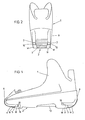
- FIG. 1 shows a side view of the shoe according to the invention
- FIG. 2 shows a view of the shoe from the heel
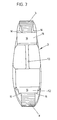
- FIG. 3 shows a view of the sole from below.
- Fig.l the shell 1 of a ski boot is shown, the sole part 2 merges into the shell on the heel side via a rounded surface area 3 and on the tip side via a rounded surface area 4.
- the surfaces 10 delimiting the grooves at the bottom run parallel to the sole plane 16, and the groove base is formed by surfaces which lie parallel to the longitudinal center plane of the shoe.
- the grooves 5 are delimited at the bottom by ribs 18 and the grooves 7 are delimited at the bottom by ribs 17.
- the end faces 15 of the ribs 18 and the end faces 14 of the ribs 17 form support surfaces for the binding in the direction of the longitudinal axis of the shoe.
- the grooves 5 and 7 are intended for the engagement of binding parts. The shoe 5 is thus held in the vertical direction and in the lateral direction by the grooves 5 and 7.
- the bracing in the longitudinal direction of the shoe is carried out by abutment of the jaws on the surfaces 15 and 14.
- the front engagement points for the binding formed by the grooves 20 and the end surfaces 15 are at a distance from the rear engagement points formed by the grooves 7 and the end surfaces 14 the binding is arranged at a distance which is unchanged for all shoe sizes or shell sizes, so that the binding can be used in an unchanged manner for all shoe sizes or shell sizes and does not have to be adjusted.
- the grooves 5 are delimited by inclined surfaces 20.
- the grooves 7 are delimited at their end facing away from the heel end 8 by inclined surfaces 19.
Landscapes
- Health & Medical Sciences (AREA)
- General Health & Medical Sciences (AREA)
- Physical Education & Sports Medicine (AREA)
- Footwear And Its Accessory, Manufacturing Method And Apparatuses (AREA)
Abstract
Description
- Die Erfindung bezieht sich auf einen Skischuh mit einer eine Laufsohle aufweisenden Schale, deren Sohlenteil über fersenseitige und schuhspitzenseitige abgerundete Flächenbereiche in die Schale übergeht und Angriffstellen für eine Bindung aufweist, wobei die Angriffstellen in für verschiedene Schalengrößen gleichbleibendem Abstand in Längsrichtung des Schuhes voneinander in Abstand von der Schuhspitze und dem Fersenende oberhalb der Sohlenebene an der Schale angeordnet sind. Eine derartige Ausbildung eines Skischuhes ist beispielsweise der US-PS 4 245 409 zu entnehmen. Diese bekannte Ausbildung weist eine für verschiedene Größen von Schuhen konstante Sohlenfläche auf, welche über abgerundete Sohlenbereiche in die Schale übergeht. Zur Festlegung von Bindungsteilen sind an den beiden Enden der Sohle der Schale sich im wesentlichen parallel zur Sohlenlängsachse erstreckende Sackbohrungen bzw. Vertiefungen vorgesehen. Die für verschiedene Schalengrößen in gleichbleibendem Abstand voneinander angeordneten Angriffstellen für die Bindung haben dabei den Vorteil, daß die Einstellung der Bindung für verschiedene Schuhgrößen in keiner Weise verändert werden muß. Es ist lediglich die Charakteristik entsprechend den jeweiligen Bedürfnissen anzupassen, für die Montage der-Bindung ergibt sich jedoch eine wesentliche Vereinfachung.
- Nachteilig bei dieser bekannten Ausbildung ist der Umstand, daß die Angriffstellen für die Bindung an der vorderen und an der hinteren Stirnfläche der Sohle vorgesehen sind und daß daher die abgerundeten Flächenbereiche, über welche der Sohlenteil in den Schalenteil übergeht, an den beiden Schuhenden nur verhältnismäßig schmal bemessen werden können. Dadurch wird ein Gehen mit dem Skischuh erschwert und es stehen überdies auch nur kleine Angriffstellen für den Angriff der Bindung am Schuh zur Verfügung. Die Ausbildung der Angriffstellen als Sackbohrungen hat weiters den Nachteil, daß diese Bohrungen durch eintretenden Schnee verlegt sein können, so daß ein sicherer Angriff der Bindungsteile gefährdet ist. Bei Anordnung von Vertiefungen dieser Art ist darüberhinaus der Halt des Schuhes gegen seitliches Verdrehen aus der Bindung nicht immer gewährleistet. Es besteht somit die Gefahr, daß sich der Schuh in unbeabsichtigter Weise von der Bindung löst bzw. daß eine korrekte Verriegelung des Schuhes mit der Bindung überhaupt nicht eintritt.
- Die Erfindung zielt nun darauf ab, die bekannte Ausbildung dahingehend weiterzubilden, daß ein sicherer Halt des Schuhes an den Bindungsteilen gewährleistet ist. Zur Lösung dieser Aufgabe besteht die Erfindung darin, daß die Angriffstellen sich in Längsrichtung der Sohle erstreckende, an den Längsseiten der Schale sowie an ihren den Schuhenden, d.h. also dem fersenseitigen Ende bzw. dem spitzenseitigen Ende des Schuhes, zugewendeten Enden nach außen offene Nuten aufweisen. Dadurch, daß die Angriffstellen als nach außen offene Nuten ausgebildet sind, kann gegebenenfalls eingetretener Schnee aus diesen Nuten leicht entfernt werden. Da sich die Nuten in Längsrichtung des Schuhes erstrecken, ergeben der Nutgrund, welcher der Längs-Mittelebene der Sohle zugewendet ist, und die die Nuten unten begrenzende Fläche ein gutes Widerlager für den Angriff von Bindungsteilen, und es läßt sich eine sichere Abstützung des Schuhes in der Bindung gewährleisten. Durch diese Nuten ist somit der Schuh gegen ein Abheben von der Bindung und gegen seitliche Verschiebung in der Bindung gesichert.
- Die Ausbildung ist hiebei vorzugsweise so getroffen, daß die Breite der abgerundeten Flächenbereiche der Sohle dem Abstand zwischen dem Grund einander relativ zur Sohlenmitte gegenüberliegender Nuten entspricht. Dadurch, daß die einander gegenüberliegenden Nuten vom Material der Sohle im Bereich der abgerundeten Flächenbereiche ausgefüllt sind, können Bindungsteile mit relativ hoher Spannkraft ohne Gefahr einer Beschädigung der Angriffstellen verwendet werden, da die Abstützung der Kräfte durch das Material der Sohle erfolgt. Die Sohle wird hiebei quer zu ihrer Längsachse beansprucht. In formtechnisch besonders einfacher Weise schließen die abgerundeten Flächenbereiche der Sohle an die Nuten an. Um ein sicheres Niederhalten der Sohle am Ski bzw. an der Platte einer Plattenbindung zu gewährleisten, ist die Ausbildung in vorteilhafter Weise so getroffen, daß die die Nuten unten begrenzenden Flächen zur Sohlenebene parallel liegen. Die zur Sohlenebene parallelen Flächen der Nuten erlauben auch hier die sichere Aufbringung der erforderlichen Haltekräfte des Schuhes relativ zur Bindung.
- Gemäß einer bevorzugten Ausführungsform der Erfindung ist die Ausbildung so getroffen, daß die den Schuhenden zugewendeten Stirnflächen von die Nuten unten begrenzenden, zwischen den Nuten und der Sohlenebene liegenden Rippen Abstützflächen für den Angriff der Bindung in Längsrichtung des Schuhes bilden. Die Abstützung des Schuhes an der Bindung in Längsrichtung des Schuhes erfolgt somit an freiliegenden Abstützflächen, wodurch vermieden ist, daß zwischen den Abstützflächen am Schuh und den Abstützflächen der Bindung sich Schnee ansammelt.
- Da diese Abstützflächen freiliegen, wird anliegender Schnee mit Sicherheit verdrängt. Die Abstützung in Längsrichtung ist daher unabhängig davon, ob beim Anlegen der Bindung noch Schnee in den seitlichen Nuten verblieben ist. Vorzugsweise sind weiters die die von den-Schuhenden abgewendeten Enden der Nuten begrenzenden Flächen schräg nach außen geneigt, so daß sie mit dem Nutgrund einen stumpfen Winkel einschließen. Auf diese Weise wird unter allen Umständen vermieden, daß in die Nuten eingedrungener Schnee sich beim Anlegen der Bindung in den Nuten hält.
- Gemäß der Erfindung weist zweckmäßig die Laufsohle sich quer zur Sohle erstreckende Stege auf, welche durch einen eine Ausnehmung in der Sohle überbrückenden, in Längsrichtung der Sohle verlaufenden Steg miteinander verbunden sind. Dadurch wird eine griffige Profilierung der Sohle geschaffen, welche ein Rutschen beim Gehen im Schnee verhindert. Insbesondere der in Längsrichtung der Sohle verlaufende Steg gibt eine große Sicherheit gegen seitliches Rutschen.
- Die Erfindung wird nachfolgend an Hand eines in der Zeichnung dargestellten Ausführungsbeispieles näher erläutert. In dieser zeigen: Fig. 1 eine Seitenansicht des erfindungsgemäßen Schuhes, Fig. 2 eine Ansicht des Schuhes von der Ferse und Fig. 3 eine Ansicht der Sohle von unten.
- In Fig.l ist die Schale 1 eines Skischuhes dargestellt, deren Sohlenteil 2 fersenseitig über einen abgerundeten Flächenbereich 3 und spitzenseitig über einen abgerundeten Flächenbereich 4 in die Schale übergeht.
- An beiden Seiten des Schuhes sind seitlich von der Sohle in Abstand von der Schuhspitze 6 Nuten 5 und in Abstand vcm Fersenende 8 Nuten 7 vorgesehen. Die die Nuten unten begrenzenden Flächen 10 verlaufen parallel zur Sohlenebene 16, und der Nutengrund ist von Flächen gebildet, welche parallel zur Längs-Mittelebene des Schuhes liegen. Die Nuten 5 sind unten durch Rippen 18 begrenzt und die Nuten 7 sind unten durch Rippen 17 begrenzt. Die Endflächen 15 der Rippen 18 und die Endflächen 14 der Rippen 17 bilden Abstützflächen für die Bindung in Richtung der Längsachse des Schuhes. Die Nuten 5 und 7 sind für den Eingriff von Bindungsteilen bestimmt. Durch die Nuten 5 und 7 wird somit der Schuh in Höhenrichtung und in Seitenrichtung festgehalten. Die Verspannung in Längsrichtung des Schuhes erfolgt durch Anlage der Backen an die Flächen 15 und 14. Die von den Nuten 20 und den Endflächen 15 gebildeten vorderen Angriffsstellen für die Bindung sind in einem Abstand von von den Nuten 7 und den Endflächen 14 gebildeten hinteren Angriffsstellen für die Bindung in einem Abstand angeordnet, welcher für alle Schuhgrößen bzw. Schalengrößen unverändert gleich ist, so daß die Bindung in unveränderter Weise für alle Schuhgrößen bzw. Schalengrößen verwendet werden kann und nicht verstellt werden muß. An dem von der Schuhspitze 6 abgewendeten Ende sind die Nuten 5 durch Schrägflächen 20 begrenzt. Die Nuten 7 sind an ihrem vom Fersenende 8 abgewendeten Ende durch Schrägflächen 19 begrenzt. Diese Schrägflächen 20 und 19 sind schräg nach außen geneigt und schließen mit dem Nutgrund einen stumpfen Winkel ein, so daß in die Nuten eingedrungener Schnee nach außen aus den Nuten herausgedrückt wird und den Sitz der Bindung nicht beeinträchtigen kann. Die Endflächen 15 und 14 liegen frei, so daß dort an sich nicht die Möglichkeit besteht, daß sich Schnee ansetzt. Aus der Unteransicht gemäß Fig.3 ergibt sich, daß die Sohle lediglich über Querstege 11 und 12 sowie einen Teil der abgerundeten Flächenbereiche 3 und 4 am Boden bzw. an der SkiOberfläche anliegt. Ein weiterer Teilbereich der Sohle ist lediglich durch einen in Längsrichtung der Sohle verlaufenden Steg 13 überbrückt. Dadurch wird die Gefahr, daß sich an der Schuhsohle Schnee ansetzt, welcher das Aufliegen des Schuhes auf dem Ski behindert, verringert. Diese Rippe ergibt überdies auch beim Gehen einen Schutz gegen seitliches Abrutschen.
Claims (7)
Applications Claiming Priority (2)
| Application Number | Priority Date | Filing Date | Title |
|---|---|---|---|
| AT0039682A AT381218B (de) | 1982-02-03 | 1982-02-03 | Skischuh |
| AT396/82 | 1982-02-03 |
Publications (2)
| Publication Number | Publication Date |
|---|---|
| EP0085669A1 true EP0085669A1 (de) | 1983-08-10 |
| EP0085669B1 EP0085669B1 (de) | 1985-10-16 |
Family
ID=3489489
Family Applications (1)
| Application Number | Title | Priority Date | Filing Date |
|---|---|---|---|
| EP83890014A Expired EP0085669B1 (de) | 1982-02-03 | 1983-02-03 | Skischuh |
Country Status (3)
| Country | Link |
|---|---|
| EP (1) | EP0085669B1 (de) |
| AT (2) | AT381218B (de) |
| DE (1) | DE3361002D1 (de) |
Cited By (5)
| Publication number | Priority date | Publication date | Assignee | Title |
|---|---|---|---|---|
| EP0133491A1 (de) * | 1983-08-03 | 1985-02-27 | NORDICA S.p.A | Skischuhstruktur mit konstanter Sohlenlänge |
| AT401330B (de) * | 1990-03-09 | 1996-08-26 | Atomic Austria Gmbh | Schischuh mit einer längenausgleichs- und bzw. oder dämpfungsvorrichtung |
| CH688637A5 (fr) * | 1993-06-30 | 1997-12-31 | Lange Int Sa | Chaussure de ski. |
| CH688636A5 (fr) * | 1993-06-30 | 1997-12-31 | Lange Int Sa | Chaussure de ski. |
| CH688638A5 (fr) * | 1993-06-30 | 1997-12-31 | Lange Int Sa | Chaussure de ski. |
Families Citing this family (1)
| Publication number | Priority date | Publication date | Assignee | Title |
|---|---|---|---|---|
| FR2654591B1 (fr) * | 1989-11-22 | 1992-02-28 | Salomon Sa | Chaussure de ski de piste. |
Citations (3)
| Publication number | Priority date | Publication date | Assignee | Title |
|---|---|---|---|---|
| CH593031A5 (en) * | 1974-03-08 | 1977-11-15 | Gertsch Ag Zug | Ski boot with attached binding elements - has groove matching shape of wedge fitting to reduce side play of boot |
| FR2410447A1 (fr) * | 1977-12-02 | 1979-06-29 | Beyl Jean Joseph Alfred | Chaussure de ski |
| EP0059022A2 (de) * | 1981-02-23 | 1982-09-01 | Lange International S.A. | Kunststoff-Skistiefel, geeignet zur lösbaren Befestigung an einem Ski |
-
1982
- 1982-02-03 AT AT0039682A patent/AT381218B/de not_active IP Right Cessation
-
1983
- 1983-02-03 DE DE8383890014T patent/DE3361002D1/de not_active Expired
- 1983-02-03 AT AT83890014T patent/ATE16076T1/de active
- 1983-02-03 EP EP83890014A patent/EP0085669B1/de not_active Expired
Patent Citations (3)
| Publication number | Priority date | Publication date | Assignee | Title |
|---|---|---|---|---|
| CH593031A5 (en) * | 1974-03-08 | 1977-11-15 | Gertsch Ag Zug | Ski boot with attached binding elements - has groove matching shape of wedge fitting to reduce side play of boot |
| FR2410447A1 (fr) * | 1977-12-02 | 1979-06-29 | Beyl Jean Joseph Alfred | Chaussure de ski |
| EP0059022A2 (de) * | 1981-02-23 | 1982-09-01 | Lange International S.A. | Kunststoff-Skistiefel, geeignet zur lösbaren Befestigung an einem Ski |
Cited By (5)
| Publication number | Priority date | Publication date | Assignee | Title |
|---|---|---|---|---|
| EP0133491A1 (de) * | 1983-08-03 | 1985-02-27 | NORDICA S.p.A | Skischuhstruktur mit konstanter Sohlenlänge |
| AT401330B (de) * | 1990-03-09 | 1996-08-26 | Atomic Austria Gmbh | Schischuh mit einer längenausgleichs- und bzw. oder dämpfungsvorrichtung |
| CH688637A5 (fr) * | 1993-06-30 | 1997-12-31 | Lange Int Sa | Chaussure de ski. |
| CH688636A5 (fr) * | 1993-06-30 | 1997-12-31 | Lange Int Sa | Chaussure de ski. |
| CH688638A5 (fr) * | 1993-06-30 | 1997-12-31 | Lange Int Sa | Chaussure de ski. |
Also Published As
| Publication number | Publication date |
|---|---|
| EP0085669B1 (de) | 1985-10-16 |
| DE3361002D1 (en) | 1985-11-21 |
| ATA39682A (de) | 1986-02-15 |
| ATE16076T1 (de) | 1985-11-15 |
| AT381218B (de) | 1986-09-10 |
Similar Documents
| Publication | Publication Date | Title |
|---|---|---|
| AT401884B (de) | Schuh, insbesondere einspuriger roll- und/oder eislaufschuh | |
| DE3742918A1 (de) | Alpiner skischuh | |
| DE4223167A1 (de) | Spike fuer laufschuhe | |
| DE2627305A1 (de) | Skisicherheitsbindung | |
| DD146791A5 (de) | Bindungsanordnung fuer einen skischuh an einem ski | |
| WO1980000540A1 (en) | Cross country ski boot adapted to a lateral guiding device on the ski | |
| DE202010018184U1 (de) | Kopplungselement für einen Skischuh und Skischuh | |
| DE2718497C2 (de) | Skibindung | |
| AT404898B (de) | Bindung und schuh für gleitbretter | |
| DE3001247A1 (de) | Anordnung zum befestigen eines stiefels auf einem ski | |
| EP0085669B1 (de) | Skischuh | |
| DE69919439T2 (de) | Trägerplatte zwischen Schuh und Snowboard | |
| DE3707116A1 (de) | Anordnung zum festhalten eines ski-schuhs auf einem langlauf- oder touren-ski | |
| DE3447012C2 (de) | Vorrichtung aus einer auf einem Ski befestigten Sicherheitsskibindung und einem Skistiefel sowie Skistiefel und Skibindung | |
| DE2548667A1 (de) | Skibremse | |
| EP0070513A1 (de) | Langlaufski | |
| DE60004110T2 (de) | Schischuh | |
| EP0129535A1 (de) | Einheit aus Langlaufbindung und Langlaufschuhen | |
| DE2906484A1 (de) | Langlauf-skischuh | |
| CH672431A5 (de) | ||
| DE3526298A1 (de) | Schuh, insbesondere sportschuh mit austauschbarem laufsohlenteil | |
| EP0595170A1 (de) | Sohlenauflageplatte | |
| AT357078B (de) | Skibindung mit einem zusatzgeraet zum tourengehen | |
| EP0221190B1 (de) | Skibindung | |
| AT521562B1 (de) | Skischuh, umfassend Kopplungselement zur Steigeisenbefestigung |
Legal Events
| Date | Code | Title | Description |
|---|---|---|---|
| PUAI | Public reference made under article 153(3) epc to a published international application that has entered the european phase |
Free format text: ORIGINAL CODE: 0009012 |
|
| AK | Designated contracting states |
Designated state(s): AT CH DE FR IT LI SE |
|
| 17P | Request for examination filed |
Effective date: 19831014 |
|
| ITF | It: translation for a ep patent filed |
Owner name: BARZANO' E ZANARDO MILANO S.P.A. |
|
| GRAA | (expected) grant |
Free format text: ORIGINAL CODE: 0009210 |
|
| AK | Designated contracting states |
Designated state(s): AT CH DE FR IT LI SE |
|
| REF | Corresponds to: |
Ref document number: 16076 Country of ref document: AT Date of ref document: 19851115 Kind code of ref document: T |
|
| PG25 | Lapsed in a contracting state [announced via postgrant information from national office to epo] |
Ref country code: SE Effective date: 19851030 |
|
| REF | Corresponds to: |
Ref document number: 3361002 Country of ref document: DE Date of ref document: 19851121 |
|
| ET | Fr: translation filed | ||
| PLBE | No opposition filed within time limit |
Free format text: ORIGINAL CODE: 0009261 |
|
| STAA | Information on the status of an ep patent application or granted ep patent |
Free format text: STATUS: NO OPPOSITION FILED WITHIN TIME LIMIT |
|
| 26N | No opposition filed | ||
| ITTA | It: last paid annual fee | ||
| PGFP | Annual fee paid to national office [announced via postgrant information from national office to epo] |
Ref country code: FR Payment date: 19970117 Year of fee payment: 15 |
|
| PGFP | Annual fee paid to national office [announced via postgrant information from national office to epo] |
Ref country code: CH Payment date: 19970124 Year of fee payment: 15 |
|
| PGFP | Annual fee paid to national office [announced via postgrant information from national office to epo] |
Ref country code: AT Payment date: 19970224 Year of fee payment: 15 |
|
| PGFP | Annual fee paid to national office [announced via postgrant information from national office to epo] |
Ref country code: DE Payment date: 19970430 Year of fee payment: 15 |
|
| REG | Reference to a national code |
Ref country code: CH Ref legal event code: PFA Free format text: KOFLACH SPORTGERAETE GESELLSCHAFT MBH TRANSFER- CZERWENKA GMBH * KOFLACH SPORT GESELLSCHAFT MBH & CO. KG TRANSFER- KOFLACH SPORT GESELLSCHAFT M.B.H. * CZERWENKA GMBH TRANSFER- KOFLACH SPORT GESELLSCHAFT MBH & CO. KG |
|
| PG25 | Lapsed in a contracting state [announced via postgrant information from national office to epo] |
Ref country code: AT Free format text: LAPSE BECAUSE OF NON-PAYMENT OF DUE FEES Effective date: 19980203 |
|
| PG25 | Lapsed in a contracting state [announced via postgrant information from national office to epo] |
Ref country code: LI Free format text: LAPSE BECAUSE OF NON-PAYMENT OF DUE FEES Effective date: 19980228 Ref country code: FR Free format text: THE PATENT HAS BEEN ANNULLED BY A DECISION OF A NATIONAL AUTHORITY Effective date: 19980228 Ref country code: CH Free format text: LAPSE BECAUSE OF NON-PAYMENT OF DUE FEES Effective date: 19980228 |
|
| REG | Reference to a national code |
Ref country code: FR Ref legal event code: TP Ref country code: FR Ref legal event code: CA |
|
| REG | Reference to a national code |
Ref country code: CH Ref legal event code: PL |
|
| PG25 | Lapsed in a contracting state [announced via postgrant information from national office to epo] |
Ref country code: DE Free format text: LAPSE BECAUSE OF NON-PAYMENT OF DUE FEES Effective date: 19981103 |
|
| REG | Reference to a national code |
Ref country code: FR Ref legal event code: ST |