EP0084197B1 - Transmission avec engrenages à mouvement orbital - Google Patents
Transmission avec engrenages à mouvement orbital Download PDFInfo
- Publication number
- EP0084197B1 EP0084197B1 EP82201659A EP82201659A EP0084197B1 EP 0084197 B1 EP0084197 B1 EP 0084197B1 EP 82201659 A EP82201659 A EP 82201659A EP 82201659 A EP82201659 A EP 82201659A EP 0084197 B1 EP0084197 B1 EP 0084197B1
- Authority
- EP
- European Patent Office
- Prior art keywords
- planet
- wheels
- gear
- teeth
- wheel
- Prior art date
- Legal status (The legal status is an assumption and is not a legal conclusion. Google has not performed a legal analysis and makes no representation as to the accuracy of the status listed.)
- Expired
Links
Images

Classifications
-
- F—MECHANICAL ENGINEERING; LIGHTING; HEATING; WEAPONS; BLASTING
- F16—ENGINEERING ELEMENTS AND UNITS; GENERAL MEASURES FOR PRODUCING AND MAINTAINING EFFECTIVE FUNCTIONING OF MACHINES OR INSTALLATIONS; THERMAL INSULATION IN GENERAL
- F16H—GEARING
- F16H1/00—Toothed gearings for conveying rotary motion
- F16H1/28—Toothed gearings for conveying rotary motion with gears having orbital motion
- F16H1/2809—Toothed gearings for conveying rotary motion with gears having orbital motion with means for equalising the distribution of load on the planet-wheels
- F16H1/2836—Toothed gearings for conveying rotary motion with gears having orbital motion with means for equalising the distribution of load on the planet-wheels by allowing limited movement of the planets relative to the planet carrier or by using free floating planets
-
- F—MECHANICAL ENGINEERING; LIGHTING; HEATING; WEAPONS; BLASTING
- F16—ENGINEERING ELEMENTS AND UNITS; GENERAL MEASURES FOR PRODUCING AND MAINTAINING EFFECTIVE FUNCTIONING OF MACHINES OR INSTALLATIONS; THERMAL INSULATION IN GENERAL
- F16C—SHAFTS; FLEXIBLE SHAFTS; ELEMENTS OR CRANKSHAFT MECHANISMS; ROTARY BODIES OTHER THAN GEARING ELEMENTS; BEARINGS
- F16C27/00—Elastic or yielding bearings or bearing supports, for exclusively rotary movement
- F16C27/02—Sliding-contact bearings
-
- F—MECHANICAL ENGINEERING; LIGHTING; HEATING; WEAPONS; BLASTING
- F16—ENGINEERING ELEMENTS AND UNITS; GENERAL MEASURES FOR PRODUCING AND MAINTAINING EFFECTIVE FUNCTIONING OF MACHINES OR INSTALLATIONS; THERMAL INSULATION IN GENERAL
- F16H—GEARING
- F16H1/00—Toothed gearings for conveying rotary motion
- F16H1/28—Toothed gearings for conveying rotary motion with gears having orbital motion
- F16H1/2863—Arrangements for adjusting or for taking-up backlash
-
- F—MECHANICAL ENGINEERING; LIGHTING; HEATING; WEAPONS; BLASTING
- F16—ENGINEERING ELEMENTS AND UNITS; GENERAL MEASURES FOR PRODUCING AND MAINTAINING EFFECTIVE FUNCTIONING OF MACHINES OR INSTALLATIONS; THERMAL INSULATION IN GENERAL
- F16H—GEARING
- F16H55/00—Elements with teeth or friction surfaces for conveying motion; Worms, pulleys or sheaves for gearing mechanisms
- F16H55/02—Toothed members; Worms
- F16H55/08—Profiling
- F16H55/0886—Profiling with corrections along the width, e.g. flank width crowning for better load distribution
-
- F—MECHANICAL ENGINEERING; LIGHTING; HEATING; WEAPONS; BLASTING
- F16—ENGINEERING ELEMENTS AND UNITS; GENERAL MEASURES FOR PRODUCING AND MAINTAINING EFFECTIVE FUNCTIONING OF MACHINES OR INSTALLATIONS; THERMAL INSULATION IN GENERAL
- F16H—GEARING
- F16H57/00—General details of gearing
- F16H57/12—Arrangements for adjusting or for taking-up backlash not provided for elsewhere
-
- F—MECHANICAL ENGINEERING; LIGHTING; HEATING; WEAPONS; BLASTING
- F16—ENGINEERING ELEMENTS AND UNITS; GENERAL MEASURES FOR PRODUCING AND MAINTAINING EFFECTIVE FUNCTIONING OF MACHINES OR INSTALLATIONS; THERMAL INSULATION IN GENERAL
- F16C—SHAFTS; FLEXIBLE SHAFTS; ELEMENTS OR CRANKSHAFT MECHANISMS; ROTARY BODIES OTHER THAN GEARING ELEMENTS; BEARINGS
- F16C23/00—Bearings for exclusively rotary movement adjustable for aligning or positioning
- F16C23/02—Sliding-contact bearings
- F16C23/04—Sliding-contact bearings self-adjusting
- F16C23/043—Sliding-contact bearings self-adjusting with spherical surfaces, e.g. spherical plain bearings
- F16C23/045—Sliding-contact bearings self-adjusting with spherical surfaces, e.g. spherical plain bearings for radial load mainly, e.g. radial spherical plain bearings
-
- F—MECHANICAL ENGINEERING; LIGHTING; HEATING; WEAPONS; BLASTING
- F16—ENGINEERING ELEMENTS AND UNITS; GENERAL MEASURES FOR PRODUCING AND MAINTAINING EFFECTIVE FUNCTIONING OF MACHINES OR INSTALLATIONS; THERMAL INSULATION IN GENERAL
- F16C—SHAFTS; FLEXIBLE SHAFTS; ELEMENTS OR CRANKSHAFT MECHANISMS; ROTARY BODIES OTHER THAN GEARING ELEMENTS; BEARINGS
- F16C2361/00—Apparatus or articles in engineering in general
- F16C2361/61—Toothed gear systems, e.g. support of pinion shafts
-
- F—MECHANICAL ENGINEERING; LIGHTING; HEATING; WEAPONS; BLASTING
- F16—ENGINEERING ELEMENTS AND UNITS; GENERAL MEASURES FOR PRODUCING AND MAINTAINING EFFECTIVE FUNCTIONING OF MACHINES OR INSTALLATIONS; THERMAL INSULATION IN GENERAL
- F16H—GEARING
- F16H57/00—General details of gearing
- F16H57/12—Arrangements for adjusting or for taking-up backlash not provided for elsewhere
- F16H2057/126—Self-adjusting during operation, e.g. by a spring
- F16H2057/127—Self-adjusting during operation, e.g. by a spring using springs
-
- F—MECHANICAL ENGINEERING; LIGHTING; HEATING; WEAPONS; BLASTING
- F16—ENGINEERING ELEMENTS AND UNITS; GENERAL MEASURES FOR PRODUCING AND MAINTAINING EFFECTIVE FUNCTIONING OF MACHINES OR INSTALLATIONS; THERMAL INSULATION IN GENERAL
- F16H—GEARING
- F16H57/00—General details of gearing
- F16H57/12—Arrangements for adjusting or for taking-up backlash not provided for elsewhere
- F16H2057/128—Arrangements for adjusting or for taking-up backlash not provided for elsewhere using axial positioning of gear wheel with addendum modification on gear width, i.e. backlash is compensated by axial positioning of a slightly conical gear wheel
-
- F—MECHANICAL ENGINEERING; LIGHTING; HEATING; WEAPONS; BLASTING
- F16—ENGINEERING ELEMENTS AND UNITS; GENERAL MEASURES FOR PRODUCING AND MAINTAINING EFFECTIVE FUNCTIONING OF MACHINES OR INSTALLATIONS; THERMAL INSULATION IN GENERAL
- F16H—GEARING
- F16H55/00—Elements with teeth or friction surfaces for conveying motion; Worms, pulleys or sheaves for gearing mechanisms
- F16H55/02—Toothed members; Worms
- F16H55/14—Construction providing resilience or vibration-damping
- F16H55/16—Construction providing resilience or vibration-damping relating to teeth only
-
- Y—GENERAL TAGGING OF NEW TECHNOLOGICAL DEVELOPMENTS; GENERAL TAGGING OF CROSS-SECTIONAL TECHNOLOGIES SPANNING OVER SEVERAL SECTIONS OF THE IPC; TECHNICAL SUBJECTS COVERED BY FORMER USPC CROSS-REFERENCE ART COLLECTIONS [XRACs] AND DIGESTS
- Y10—TECHNICAL SUBJECTS COVERED BY FORMER USPC
- Y10T—TECHNICAL SUBJECTS COVERED BY FORMER US CLASSIFICATION
- Y10T74/00—Machine element or mechanism
- Y10T74/19—Gearing
- Y10T74/19623—Backlash take-up
-
- Y—GENERAL TAGGING OF NEW TECHNOLOGICAL DEVELOPMENTS; GENERAL TAGGING OF CROSS-SECTIONAL TECHNOLOGIES SPANNING OVER SEVERAL SECTIONS OF THE IPC; TECHNICAL SUBJECTS COVERED BY FORMER USPC CROSS-REFERENCE ART COLLECTIONS [XRACs] AND DIGESTS
- Y10—TECHNICAL SUBJECTS COVERED BY FORMER USPC
- Y10T—TECHNICAL SUBJECTS COVERED BY FORMER US CLASSIFICATION
- Y10T74/00—Machine element or mechanism
- Y10T74/19—Gearing
- Y10T74/19949—Teeth
- Y10T74/19963—Spur
- Y10T74/19972—Spur form
Definitions
- the invention relates to a planetary gear with the features specified in the preamble of claim 1.
- Such a planetary gear is known (DE-OS 2 558 093) and constructed so that the planetary web with the planet gears is axially immovable, while the sun gear and the ring gear are axially movable and are acted upon by an axially acting force, in particular by springs. Due to the constantly changing profile shifting of the spur gears, the wheels should be able to slide axially into one another until they mesh with one another practically without play, whereby manufacturing tolerances are to be equalized. In order to also achieve load balancing, the axially movable wheels are also slightly radially movable.
- the sun gear can be driven via a coupling sleeve, which has internal gears at both end regions and into which a shaft journal with external gearing formed on the sun gear engages from one side and the drive shaft, which is also provided with external gearing, engages from the other side.
- a compression spring lies between this drive shaft and the shaft journal.
- the sun gear and the large and heavy ring gear must therefore be mounted axially and radially displaceably using special coupling sleeves with internal toothing, which means a complicated structure.
- the desired self-adjustment is complicated by the fact that the heavy mass of the ring gear has to be moved axially and / or radially, usually in a rapid periodic sequence, which depends on the rotational speed of the planet gears.
- the required periodic accelerations of a relatively large inertial mass mean undesirable losses and stresses and can lead to disturbing vibrations.
- the profile displacements on both gearwheels must change in opposite directions such that the sum of the profile displacements, taking into account their signs, has the same value for each latitude coordinate of the tooth engagement.
- Planetary gears with helically toothed wheels are also known (DE-OS 2363106), in which the planet wheels are axially resiliently mounted on the web axes. In this way, a power split is to be achieved with normal manufacturing tolerances.
- the radially non-compliant planet gears are provided with two oppositely inclined gears, which complicates manufacture and increases the axial dimension.
- planetary gears are known in which the planet gears are spherical or are mounted on self-aligning bearings in order to achieve a load distribution that is as uniform as possible (DE-PS 503 307 and US Pat. No. 3 178 966).
- the invention has for its object to provide a planetary gear with the features specified in the preamble of claim 1 so that, with a simple structure and without the need for precision machining, on the one hand the mechanical flank or engagement play is practically completely suppressed and on the other hand inaccuracies of concentricity automatically be compensated and even with larger toothing tolerances all planet gears are always in an optimal manner with the sun gear and the ring gear in engagement, so that a uniform distribution of the load and the forces to be transmitted is guaranteed.
- Such a planetary gear according to the invention has a very simple and stable structure. All wheels can be manufactured with conventional hob cutters and machines and do not require high machining precision; in particular, no ground wheels are required.
- This simple manufacture in connection with the simple assembly allows a very inexpensive manufacture, so that for the first time inexpensive, practically backlash-free planetary gears with a backlash of less than one arc minute and with practically perfect load balancing are available, which are used in applications that require a very high positional accuracy , which can replace the previously necessary expensive special gearboxes.
- the planet gears were only axially preloaded without being radially flexible, if the gear wheels were not aligned correctly or if the concentricity was not perfect, they would currently only be firmly pressed into engagement with one of the other gears, ring gear or sun gear, while meshing with the other The wheel would be more or less loose, which would result in a play between the sun gear and the ring gear.
- the planet gears were only on self-aligning bearings and were not also axially displaceable, they could get stuck when they tilt.
- each planet gear is individually axially adjusted and, due to its oscillating mounting, can be tilted individually within certain limits about axes oriented perpendicular to the planet gear axis and also has convex toothing, that is, tooth flanks rounded in the axial direction, can all planet gears due to the degrees of freedom mentioned under the effect the suitably chosen axial contact force engage so far and so strongly in the toothing of the sun gear and the ring gear that there is always a virtually complete freedom from play. Manufacturing tolerances, gearing errors and inaccuracies in concentricity, which can occur primarily as a result of a deformation or an inexact concentricity of the ring gear, are automatically compensated for.
- each planet gear is forcibly held in full engagement with the teeth of the sun gear and the ring gear, an exact load balancing is also guaranteed.
- the mean radii and the degree of crowning of the toothings are chosen so that the contact points of interacting tooth flanks are at least approximately in the middle of the tooth widths.
- the crowning of the toothing eliminates the need for exact axial alignment of the wheels, and so-called edge runners are avoided.
- the cone angle of the cones enveloping the tooth tips of all wheels is advantageously between 6 ° and 15 °, in particular approximately 10 °.
- the wheels of the planetary gear according to the invention preferably have normal involute teeth.
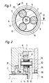
- a first shaft 3 is rotatably mounted in the housing 1 of the planetary gear by means of a ball bearing 2, which is axially immovable.
- the sun gear 4 is fixed with its teeth 5 in a rotationally fixed and axially immovable manner.
- a ring gear 6 with its internal toothing 7 is immovably fixed in the housing 1.
- three planet gears 8 with their toothings 9 are arranged uniformly distributed according to FIG. 1, which mesh with both the sun gear 4 and the ring gear 6.
- Each planet gear 9 is axially displaceable and mounted on its planet gear shaft 10 so that it can be tilted within certain limits by means of a self-aligning bearing 11.
- All planet gear shafts 10 are carried by the common planet web 15, to which a second shaft 16 is fastened coaxially to the first shaft 3.
- the planetary web 15 and the shaft 16 attached to it are rotatably mounted axially immovably in the housing 1 by means of ball bearings 17 and 18.
- the planetary gear described is preferably a reduction gear mounted directly on a servomotor, the shaft 3 being the drive shaft, that is to say the motor shaft or an input shaft coupled to the motor shaft, while the shaft 16 coaxial therewith represents the output shaft.
- a desired reduction ratio can be achieved within a wide reduction range, in particular also a relatively small reduction ratio, which often cannot be achieved or can only be achieved with complicated construction with low-backlash or backlash-free transmissions of conventional design.
- the self-aligning bearing 11 consists of a bearing sleeve 12 which is freely rotatable and axially displaceable on the relevant planet gear shaft 10, a bearing head 13 which is seated thereon and is spherically curved on the outside and forms a type of joint ball, and the outer bearing ring 14 which supports the planet gear 8. which sits with its adapted hollow spherical inner circumference on the bearing head 13.
- the bearing ring 14 can therefore slide on the bearing head 13 in the manner of a ball joint socket and can thus be pivoted within certain limits, so that the planet gear 8 can tilt within a certain angle about an axis oriented perpendicular to the planet gear shaft 10.
- the sun gear 4, the planet gears 8 and the ring gear 6 are spur gears and have an involute toothing with a profile shift which varies continuously in the axial direction, i.e. over the tooth width, which in the sun gear 4 and the ring gear 6 changes from a positive shift on the drive side to one negative displacement on the output side of the wheels changes and varies in the reverse sense for the planet gears 8.
- the tip of the cone going through the tooth tip lines of the sun gear 4 is therefore according to FIG. 2 on the driven side, while the cone tips in question for the planet gears 8 and the ring gear 6 are on the drive side.
- the cone angles are between a minimum of 6 ° and a maximum of 15 °, preferably around 10 °. At cone angles below about 6 ° there is a risk of self-locking such that the planet gears 8 no longer perform an axial evasive movement under the effect of a force exerted radially on them, which results, for example, from a concentricity error, that is to say in the illustration according to FIG 2 is directed to the right, towards the driven side.
- a plate spring or also a plate spring assembly is arranged on the planet gear shaft 10 as an elastic pressure element 19.
- FIG. 3 shows a partial view in the direction of arrow 111 according to FIG. 2 of the interacting toothings 5 and 9 of the sun gear 4 and a planet gear 8;
- the cross-sectional profiles of the teeth on the drive side are drawn with full lines and those on the output side are shown in dashed lines.
- the fairly thick cross-sectional profile of the teeth of the sun gear teeth 5 tapers on the drive side from the tooth thickness d1, with a simultaneous change in the tooth profiles, down to a tooth thickness d2 on the driven side; the taper and the change in profile of the teeth of the planetary gear teeth 9 run in the opposite direction.
- the cross-sectional profile on the tapered side of the teeth can be slightly undercut.
- the teeth of all wheels have a crown, as illustrated schematically in FIG. 4, which shows a top view of the end faces of two interacting teeth of the sun gear teeth 5 and the planet gear teeth 9.
- the tooth flanks are convex in the direction of the tooth width, that is to say convexly curved, so that the exact engagement is insensitive to small toothing and assembly errors and edge running is avoided.
- FIG. 4 those already in FIG. 3 are also shown Drawn tooth thicknesses d1 and d2 of the planetary gear teeth 5 on the drive side and on the output side respectively.
- the described design of the planetary gear according to the invention which is inexpensive to produce with conventional machines, for example with normal milling machines, gives the planet gears, with axially immovable sun gear, ring gear and planetary web, degrees of freedom of orientation such that they inevitably also with gear and assembly errors as well as in the case of imprecise concentricity are kept in optimal engagement and thus guarantee both practically absolute backlash and a completely even load distribution.
- planet gears generally have a smaller mass than the ring gear, which of course facilitates self-adjustment.
- the diameter of the internal toothing 7 of the ring gear 6 is, for example, 135 mm, and the diameter of the Finrades4 and the three planet gears 8 are approximately the same size.
- the spring force of the plate springs 19 can typically be approximately 1 kg, the cone angle of all wheels of the transmission being approximately 10 °. The measured backlash of such a planetary gear was determined to be less than one arc minute.
- the teeth of the planet gears and / or the sun gear and / or the ring gear may be provided with radial slots opening at the tooth tips, as a result of which a certain elasticity of the tooth sections divided by the slots reached or the elasticity of the teeth is increased.
- the teeth 9 of the planet gears 8 have radial slots 21 and the teeth 5 of the sun gear 4 have radial slots 20.
- the invention is not limited to the described embodiment, but allows multiple variants, in particular with regard to the design of the self-aligning bearings, for which self-aligning ball bearings can also be used, the type of pressure elements for the planet gears and the number of planet gears.
Landscapes
- Engineering & Computer Science (AREA)
- General Engineering & Computer Science (AREA)
- Mechanical Engineering (AREA)
- Retarders (AREA)
Claims (4)
Applications Claiming Priority (2)
| Application Number | Priority Date | Filing Date | Title |
|---|---|---|---|
| CH271/82 | 1982-01-18 | ||
| CH27182 | 1982-01-18 |
Publications (2)
| Publication Number | Publication Date |
|---|---|
| EP0084197A1 EP0084197A1 (fr) | 1983-07-27 |
| EP0084197B1 true EP0084197B1 (fr) | 1985-12-04 |
Family
ID=4183200
Family Applications (1)
| Application Number | Title | Priority Date | Filing Date |
|---|---|---|---|
| EP82201659A Expired EP0084197B1 (fr) | 1982-01-18 | 1982-12-24 | Transmission avec engrenages à mouvement orbital |
Country Status (4)
| Country | Link |
|---|---|
| US (1) | US4524643A (fr) |
| EP (1) | EP0084197B1 (fr) |
| JP (1) | JPS58124849A (fr) |
| DE (1) | DE3267847D1 (fr) |
Cited By (3)
| Publication number | Priority date | Publication date | Assignee | Title |
|---|---|---|---|---|
| DE3721064A1 (de) * | 1987-06-26 | 1989-01-05 | Wittenstein Manfred | Spielfreies planetengetriebe |
| DE10318517A1 (de) * | 2003-04-24 | 2004-11-11 | Zf Friedrichshafen Ag | Planetengetriebe |
| DE102012015051A1 (de) * | 2012-07-31 | 2014-02-06 | Premium Stephan Hameln, eine Zweigniederlassung der Premium Stephan B. V. | Planetengetriebe |
Families Citing this family (65)
| Publication number | Priority date | Publication date | Assignee | Title |
|---|---|---|---|---|
| JPS6088248A (ja) * | 1983-10-20 | 1985-05-18 | Fuji Hensokuki Kk | 円すい軸と歯車推力釣合わせ装置とを用いた動力等配歯車装置 |
| JPS6065940A (ja) * | 1983-09-17 | 1985-04-15 | Fuji Hensokuki Kk | 円すい軸を用いた動力等配歯車装置 |
| WO1985001334A1 (fr) * | 1983-09-17 | 1985-03-28 | Fujihensokuki Co., Ltd. | Dispositif a engrenages |
| US4688448A (en) * | 1986-01-27 | 1987-08-25 | Itt Corporation | Drive mechanism for searchlights |
| US4750383A (en) * | 1986-08-12 | 1988-06-14 | The Gleason Works | Staggered combination gears |
| DE3734462A1 (de) * | 1987-10-12 | 1989-04-20 | Wilhelm Vogel Gmbh | Zahnradgetriebe, insbesondere stirnrad-planetengetriebe |
| DE3741634A1 (de) * | 1987-12-09 | 1989-06-22 | Wittenstein Manfred | Spielarmes ins langsame uebersetzendes zweistufiges planetengetriebe |
| GB8805290D0 (en) * | 1988-03-05 | 1988-04-07 | Ihw Eng Ltd | Seat reclining mechanism |
| US4885950A (en) * | 1989-03-20 | 1989-12-12 | The United States Of America As Represented By The Secretary Of The Army | Bevel gear backlash and clutch device |
| DE3925601A1 (de) * | 1989-08-02 | 1991-02-07 | Boehringer Werkzeugmaschinen | C-achsgetriebe |
| DE3930334C1 (fr) * | 1989-09-11 | 1990-07-26 | Index-Werke Kg Hahn & Tessky, 7300 Esslingen, De | |
| US5066211A (en) * | 1990-03-01 | 1991-11-19 | Nabisco Brands, Inc. | Material feed control assembly in a rotary press |
| GB2244538A (en) * | 1990-05-24 | 1991-12-04 | Maul Technology Co | Reducing gear train backlash |
| IT1242886B (it) * | 1990-12-17 | 1994-05-18 | Giovanni Castellani | Riduttore di velocita' a ingranaggi ad assi paralleli. |
| US5240462A (en) * | 1991-03-19 | 1993-08-31 | Isel Co., Ltd. | Planetary reduction gear |
| EP0505140A1 (fr) * | 1991-03-19 | 1992-09-23 | Isel Co., Ltd. | Engrenage planétaire de réduction |
| US5466198A (en) * | 1993-06-11 | 1995-11-14 | United Technologies Corporation | Geared drive system for a bladed propulsor |
| US5401220A (en) * | 1993-07-28 | 1995-03-28 | Peerless-Winsmith, Inc. | Speed reducer with planocentric gear arrangement |
| GB2284460A (en) * | 1993-12-06 | 1995-06-07 | Perkins Ltd | A no-backlash gearing mechanism |
| WO1996002399A1 (fr) * | 1994-07-13 | 1996-02-01 | O & K Orenstein & Koppel Ag | Procede et dispositif destines a rattraper ou a eliminer le jeu de transmission dans un engin de travaux publics freine, fonctionnant en station fixe |
| DE19712516C2 (de) * | 1997-03-25 | 2000-05-18 | C H Schaefer Getriebe Gmbh | Planetengetriebe |
| US6253047B1 (en) * | 2000-03-08 | 2001-06-26 | Xerox Corporation | Printer motion quality improvement with crowned gear drive systems |
| JP2002005245A (ja) * | 2000-06-21 | 2002-01-09 | Asada Seimitsu Haguruma Kk | 遊星歯車減速装置および遊星歯車減速装置における噛合バックラッシュ減少機構 |
| GB2373304A (en) * | 2001-02-20 | 2002-09-18 | Bryan Nigel Victor Parsons | Tapered involute gear profile |
| DE10129450A1 (de) | 2001-06-19 | 2003-01-02 | Bosch Gmbh Robert | Stellglied für eine Fahrzeug-Lenkvorrichtung |
| WO2003042574A2 (fr) * | 2001-11-13 | 2003-05-22 | Holtz, Douglas | Transmission a vis sans fin a billes |
| US6682456B2 (en) | 2001-12-10 | 2004-01-27 | Axicon Technologies, Inc. | Multi-mesh gear system |
| US6832661B2 (en) * | 2003-02-21 | 2004-12-21 | Delphi Technologies, Inc. | Delashing mechanism for fixed parallel based gear pairs |
| DE102004006723A1 (de) * | 2004-02-11 | 2005-09-01 | Zf Friedrichshafen Ag | Planetenradgetriebe |
| US20070142150A1 (en) * | 2005-10-26 | 2007-06-21 | Luk Lamellen Und Kupplungsbau Beteiligungs Kg | Link plate for a plate-link chain |
| DE102008000820A1 (de) * | 2008-03-26 | 2009-10-01 | Zf Friedrichshafen Ag | Einrichtung zur Reduzierung von Rasselgeräuschen in Mehrstufenschaltgetrieben |
| DK2265525T3 (da) | 2008-04-11 | 2014-11-10 | Anker Andersen As | Apparat og fremgangsmåde til tilføring af brugte genstande |
| US20100038192A1 (en) * | 2008-08-15 | 2010-02-18 | Culbertson Michael O | Floating yaw brake for wind turbine |
| AT508260B1 (de) * | 2009-05-20 | 2010-12-15 | Miba Sinter Austria Gmbh | Zahnrad |
| CN102049787B (zh) * | 2009-11-06 | 2014-02-19 | 鸿富锦精密工业(深圳)有限公司 | 采用齿轮侧隙调整装置的工业机器人 |
| CN102072279A (zh) * | 2009-11-20 | 2011-05-25 | 鸿富锦精密工业(深圳)有限公司 | 齿轮传动装置 |
| CN102338197B (zh) * | 2010-07-20 | 2014-01-15 | 鸿富锦精密工业(深圳)有限公司 | 齿轮传动装置及具有该齿轮传动装置的机械手臂 |
| US8646767B2 (en) * | 2010-07-23 | 2014-02-11 | Lam Research Ag | Device for holding wafer shaped articles |
| US8613142B2 (en) | 2010-07-30 | 2013-12-24 | Hamilton Sundstrand Corporation | Methods for cluster gear timing and manufacturing |
| CN102478098A (zh) * | 2010-11-22 | 2012-05-30 | 北京精密机电控制设备研究所 | 一种紧凑型零侧隙平行轴齿轮减速器 |
| JP5807355B2 (ja) * | 2011-03-22 | 2015-11-10 | セイコーエプソン株式会社 | 減速機、ロボットハンドおよびロボット |
| US8777793B2 (en) * | 2011-04-27 | 2014-07-15 | United Technologies Corporation | Fan drive planetary gear system integrated carrier and torque frame |
| JP5622716B2 (ja) * | 2011-12-28 | 2014-11-12 | 三菱重工業株式会社 | 遊星歯車装置および風力発電装置 |
| CA2968616C (fr) | 2014-01-30 | 2022-08-23 | Genesis Advanced Technology Inc. | Entrainement a rouleaux |
| DE102014008143B4 (de) * | 2014-06-07 | 2023-12-21 | Günther Zimmer | Umlaufgetriebe mit zwei Sonnenrädern und Verzahnungsspielminimierung |
| CN105447295B (zh) * | 2014-08-29 | 2018-08-14 | 上海汽车集团股份有限公司 | 行星齿轮系统及其结构参数的确定方法 |
| DE102014223019B4 (de) * | 2014-11-12 | 2016-10-13 | Schaeffler Technologies AG & Co. KG | Planetengetriebe |
| DE102014117646A1 (de) * | 2014-12-02 | 2016-06-02 | Robert Bosch Automotive Steering Gmbh | Planetengetriebe für ein lenksystem und verfahren zur montage eines planetengetriebes |
| FR3029471B1 (fr) * | 2014-12-03 | 2018-04-13 | Faurecia Sieges D'automobile | Engrenage, mecanisme de reglage comportant un tel engrenage et siege comportant un tel mecanisme |
| SE1550263A1 (en) * | 2015-03-04 | 2016-09-05 | Swepart Trans Ab | Gear train |
| US9512900B2 (en) * | 2015-05-08 | 2016-12-06 | E-Aam Driveline Systems Ab | Planetary gear mechanism with reduced gear lash |
| DE102015223119B3 (de) * | 2015-11-23 | 2017-01-12 | Bayerische Motoren Werke Aktiengesellschaft | Schrägverzahnung mit verändertem Zahneingriff |
| CN107152499A (zh) * | 2016-03-04 | 2017-09-12 | 德昌电机(深圳)有限公司 | 驱动装置 |
| DE102016207696A1 (de) * | 2016-05-04 | 2017-11-09 | Zf Friedrichshafen Ag | Getriebe mit einer an einem Tellerrad des Getriebes mechanisch angetriebenen Pumpe |
| CN105840741A (zh) * | 2016-05-23 | 2016-08-10 | 合肥波林新材料股份有限公司 | 一种背隙可调行星传动减速器 |
| DE102016120357B4 (de) * | 2016-10-25 | 2024-02-15 | Dr. Ing. H.C. F. Porsche Aktiengesellschaft | Schneckengetriebe |
| CA2959625C (fr) | 2017-03-01 | 2023-10-10 | Nova Chemicals Corporation | Surface de spinelle de fer anti-cokefaction |
| CN107166017B (zh) * | 2017-05-27 | 2019-07-26 | 燕山大学 | 一种具有止逆功能的斜置推杆活齿减速器 |
| EP3431822B1 (fr) | 2017-07-18 | 2020-09-02 | Hamilton Sundstrand Corporation | Ensemble de verrouillage et le support de broche |
| CN107387583B (zh) * | 2017-08-31 | 2023-05-16 | 重庆巴欧机电有限公司 | 一种联轴器 |
| KR102359816B1 (ko) * | 2017-09-16 | 2022-02-08 | 제네시스 어드밴스드 테크놀러지 인크. | 차동 유성 기어박스 |
| DE102018200056A1 (de) * | 2018-01-03 | 2019-07-04 | Aktiebolaget Skf | Planetengetriebe |
| US10724625B2 (en) * | 2018-02-20 | 2020-07-28 | Sikorsky Aircraft Corporation | Torsionally compliant geartrain carrier assembly |
| EP3702641A1 (fr) * | 2019-03-01 | 2020-09-02 | Honeywell International Inc. | System pour un engranage de reduction compact avec une propriete anti-backlash |
| CN111536205B (zh) * | 2020-05-21 | 2021-06-01 | 安徽津野数控科技有限公司 | 一种数控机床用低回程间隙行星减速器 |
Citations (1)
| Publication number | Priority date | Publication date | Assignee | Title |
|---|---|---|---|---|
| DE2558093A1 (de) * | 1975-12-19 | 1977-06-23 | Mannesmann Ag | Planetengetriebe |
Family Cites Families (22)
| Publication number | Priority date | Publication date | Assignee | Title |
|---|---|---|---|---|
| US618272A (en) * | 1899-01-24 | johnson | ||
| DE503307C (de) * | 1930-07-23 | Skoda Kp | Planetengetriebe | |
| DE506486C (de) * | 1930-10-10 | Demag Akt Ges | Zahnradplanetengetriebe | |
| DE1069975B (fr) * | 1959-11-26 | |||
| DE606634C (de) * | 1931-09-17 | 1934-12-06 | Vormals Skodawerke Ag | Planetengetriebe |
| US2335504A (en) * | 1942-11-13 | 1943-11-30 | Gazda Antoine | Gear tooth |
| US2516200A (en) * | 1947-08-06 | 1950-07-25 | Gen Motors Corp | Planetary gearing |
| US2682760A (en) * | 1950-04-18 | 1954-07-06 | American Flexible Coupling Com | Gear coupling |
| DE1180596B (de) * | 1959-11-14 | 1964-10-29 | Froriep Gmbh Maschf | Vorrichtung zum Einstellen des Zahnspiels bei Getrieben |
| US3178966A (en) * | 1962-02-26 | 1965-04-20 | Wildhaber Ernest | Gear drive |
| US3315547A (en) * | 1963-09-26 | 1967-04-25 | Simmering Graz Pauker Ag | Epicyclic gears |
| AT241216B (de) * | 1963-09-26 | 1965-07-12 | Simmering Graz Pauker Ag | Planetengetriebe |
| FR1416102A (fr) * | 1964-11-20 | 1965-10-29 | English Numbering Machines | Perfectionnements aux engrenages |
| CH502535A (de) * | 1969-01-29 | 1971-01-31 | Pav Praez S App Bau Ag | Mechanische Bewegungsübertragungsanordnung |
| JPS4898252A (fr) * | 1972-03-31 | 1973-12-13 | ||
| SU580391A1 (ru) * | 1973-01-18 | 1977-11-15 | Ростовский-На-Дону Ордена Трудового Красного Знамени Усудартсвенный Университет | Цилиндрическа зубчата передача с зацеплением новикова |
| JPS5024955U (fr) * | 1973-06-30 | 1975-03-20 | ||
| DE2363106C2 (de) * | 1973-12-19 | 1983-08-11 | Hermann Dr.-Ing. 3302 Cremlingen Klaue | Lastausgleichseinrichtung für einen Planetenradendantrieb schwerer Kraftfahrzeuge |
| US3943780A (en) * | 1974-07-18 | 1976-03-16 | Hermann Klaue | Planetary gear drive with power distribution |
| DE2446172A1 (de) * | 1974-09-27 | 1976-04-15 | Daimler Benz Ag | Evolventen-stirnradverzahnung |
| JPS54145773U (fr) * | 1978-03-31 | 1979-10-09 | ||
| JPS5598850U (fr) * | 1978-12-29 | 1980-07-09 |
-
1982
- 1982-12-24 EP EP82201659A patent/EP0084197B1/fr not_active Expired
- 1982-12-24 DE DE8282201659T patent/DE3267847D1/de not_active Expired
-
1983
- 1983-01-04 US US06/455,498 patent/US4524643A/en not_active Expired - Lifetime
- 1983-01-17 JP JP58004280A patent/JPS58124849A/ja active Granted
Patent Citations (1)
| Publication number | Priority date | Publication date | Assignee | Title |
|---|---|---|---|---|
| DE2558093A1 (de) * | 1975-12-19 | 1977-06-23 | Mannesmann Ag | Planetengetriebe |
Cited By (4)
| Publication number | Priority date | Publication date | Assignee | Title |
|---|---|---|---|---|
| DE3721064A1 (de) * | 1987-06-26 | 1989-01-05 | Wittenstein Manfred | Spielfreies planetengetriebe |
| DE10318517A1 (de) * | 2003-04-24 | 2004-11-11 | Zf Friedrichshafen Ag | Planetengetriebe |
| DE102012015051A1 (de) * | 2012-07-31 | 2014-02-06 | Premium Stephan Hameln, eine Zweigniederlassung der Premium Stephan B. V. | Planetengetriebe |
| EP2693079A3 (fr) * | 2012-07-31 | 2014-09-03 | Premium Stephan Hameln | Train épicycloïdal et appareil de manipulation équipé d'un tel train épicycloïdal |
Also Published As
| Publication number | Publication date |
|---|---|
| EP0084197A1 (fr) | 1983-07-27 |
| JPH0338457B2 (fr) | 1991-06-10 |
| DE3267847D1 (en) | 1986-01-16 |
| US4524643A (en) | 1985-06-25 |
| JPS58124849A (ja) | 1983-07-25 |
Similar Documents
| Publication | Publication Date | Title |
|---|---|---|
| EP0084197B1 (fr) | Transmission avec engrenages à mouvement orbital | |
| EP0981697B1 (fr) | Boite planetaire | |
| EP0316713A2 (fr) | Transmission planétaire | |
| EP2693079B1 (fr) | Train épicycloïdal et appareil de manipulation équipé d'un tel train épicycloïdal | |
| DE102004006723A1 (de) | Planetenradgetriebe | |
| DE10129450A1 (de) | Stellglied für eine Fahrzeug-Lenkvorrichtung | |
| DE3739238A1 (de) | Spielfreies kompakt-untersetzungsgetriebe | |
| EP1188002B1 (fr) | Boite planetaire | |
| DE2809243B2 (de) | Homokinetisches Dreizapfengelenk | |
| DE19900010C2 (de) | Spielfreies Reibradgetriebe | |
| DE60102453T2 (de) | Exzentergetriebe | |
| EP1747382B1 (fr) | Servomoteur électrique pour direction assistée d'un véhicule, ledit servomoteur comprenant un palier à billes ayant une bague extérieure excentrique | |
| WO1995004232A1 (fr) | Engrenage planetaire sans jeu | |
| EP0459352B1 (fr) | Transmission à dérivation de puissance | |
| DE3721064A1 (de) | Spielfreies planetengetriebe | |
| DE19961788A1 (de) | Planetengetriebeanordnung mit kleinem Spiel | |
| EP1040284B1 (fr) | Engrenage planetaire | |
| EP0719964B1 (fr) | Transmission planétaire à engrenages droits | |
| EP1616113B1 (fr) | Engrenage planetaire | |
| EP1045168A2 (fr) | Servocommande | |
| DE102019212220B4 (de) | Wellgetriebe | |
| DE102005042718A1 (de) | Werkzeug zur spanenden Bearbeitung von Werkstückoberflächen | |
| DE2458762A1 (de) | Reibrad-planetengetriebe | |
| DE102019212221A1 (de) | Wellgetriebe | |
| DE3641769A1 (de) | Antriebsanordnung |
Legal Events
| Date | Code | Title | Description |
|---|---|---|---|
| PUAI | Public reference made under article 153(3) epc to a published international application that has entered the european phase |
Free format text: ORIGINAL CODE: 0009012 |
|
| AK | Designated contracting states |
Designated state(s): CH DE FR GB IT LI SE |
|
| 17P | Request for examination filed |
Effective date: 19831223 |
|
| GRAA | (expected) grant |
Free format text: ORIGINAL CODE: 0009210 |
|
| ITF | It: translation for a ep patent filed |
Owner name: BUGNION S.P.A. |
|
| AK | Designated contracting states |
Designated state(s): CH DE FR GB IT LI SE |
|
| REF | Corresponds to: |
Ref document number: 3267847 Country of ref document: DE Date of ref document: 19860116 |
|
| ET | Fr: translation filed | ||
| PLBE | No opposition filed within time limit |
Free format text: ORIGINAL CODE: 0009261 |
|
| STAA | Information on the status of an ep patent application or granted ep patent |
Free format text: STATUS: NO OPPOSITION FILED WITHIN TIME LIMIT |
|
| 26N | No opposition filed | ||
| ITTA | It: last paid annual fee | ||
| EAL | Se: european patent in force in sweden |
Ref document number: 82201659.8 |
|
| PGFP | Annual fee paid to national office [announced via postgrant information from national office to epo] |
Ref country code: SE Payment date: 19991207 Year of fee payment: 18 |
|
| PGFP | Annual fee paid to national office [announced via postgrant information from national office to epo] |
Ref country code: FR Payment date: 20001124 Year of fee payment: 19 |
|
| PGFP | Annual fee paid to national office [announced via postgrant information from national office to epo] |
Ref country code: DE Payment date: 20001125 Year of fee payment: 19 |
|
| PGFP | Annual fee paid to national office [announced via postgrant information from national office to epo] |
Ref country code: CH Payment date: 20001130 Year of fee payment: 19 |
|
| PG25 | Lapsed in a contracting state [announced via postgrant information from national office to epo] |
Ref country code: SE Free format text: LAPSE BECAUSE OF NON-PAYMENT OF DUE FEES Effective date: 20001225 |
|
| EUG | Se: european patent has lapsed |
Ref document number: 82201659.8 |
|
| PGFP | Annual fee paid to national office [announced via postgrant information from national office to epo] |
Ref country code: GB Payment date: 20011227 Year of fee payment: 20 |
|
| PG25 | Lapsed in a contracting state [announced via postgrant information from national office to epo] |
Ref country code: LI Free format text: LAPSE BECAUSE OF NON-PAYMENT OF DUE FEES Effective date: 20011231 Ref country code: CH Free format text: LAPSE BECAUSE OF NON-PAYMENT OF DUE FEES Effective date: 20011231 |
|
| REG | Reference to a national code |
Ref country code: GB Ref legal event code: IF02 |
|
| PG25 | Lapsed in a contracting state [announced via postgrant information from national office to epo] |
Ref country code: DE Free format text: LAPSE BECAUSE OF NON-PAYMENT OF DUE FEES Effective date: 20020702 |
|
| REG | Reference to a national code |
Ref country code: CH Ref legal event code: PL |
|
| PG25 | Lapsed in a contracting state [announced via postgrant information from national office to epo] |
Ref country code: FR Free format text: LAPSE BECAUSE OF NON-PAYMENT OF DUE FEES Effective date: 20020830 |
|
| REG | Reference to a national code |
Ref country code: FR Ref legal event code: ST |
|
| PG25 | Lapsed in a contracting state [announced via postgrant information from national office to epo] |
Ref country code: GB Free format text: LAPSE BECAUSE OF EXPIRATION OF PROTECTION Effective date: 20021223 |
|
| REG | Reference to a national code |
Ref country code: GB Ref legal event code: PE20 Effective date: 20021223 |