EP0077890B1 - Elektrokettenzug - Google Patents
Elektrokettenzug Download PDFInfo
- Publication number
- EP0077890B1 EP0077890B1 EP82107167A EP82107167A EP0077890B1 EP 0077890 B1 EP0077890 B1 EP 0077890B1 EP 82107167 A EP82107167 A EP 82107167A EP 82107167 A EP82107167 A EP 82107167A EP 0077890 B1 EP0077890 B1 EP 0077890B1
- Authority
- EP
- European Patent Office
- Prior art keywords
- gear shaft
- gear
- toothed wheel
- reduction gearing
- wheel
- Prior art date
- Legal status (The legal status is an assumption and is not a legal conclusion. Google has not performed a legal analysis and makes no representation as to the accuracy of the status listed.)
- Expired
Links
- 230000008878 coupling Effects 0.000 claims abstract description 12
- 238000010168 coupling process Methods 0.000 claims abstract description 12
- 238000005859 coupling reaction Methods 0.000 claims abstract description 12
- 239000000725 suspension Substances 0.000 claims abstract description 6
- 238000010276 construction Methods 0.000 claims abstract description 3
- 238000005096 rolling process Methods 0.000 claims abstract description 3
- 230000005540 biological transmission Effects 0.000 description 6
- 238000000034 method Methods 0.000 description 2
- 230000036316 preload Effects 0.000 description 2
- 230000006835 compression Effects 0.000 description 1
- 238000007906 compression Methods 0.000 description 1
- 238000006073 displacement reaction Methods 0.000 description 1
- 239000002184 metal Substances 0.000 description 1
Images


Classifications
-
- B—PERFORMING OPERATIONS; TRANSPORTING
- B66—HOISTING; LIFTING; HAULING
- B66D—CAPSTANS; WINCHES; TACKLES, e.g. PULLEY BLOCKS; HOISTS
- B66D3/00—Portable or mobile lifting or hauling appliances
- B66D3/18—Power-operated hoists
- B66D3/20—Power-operated hoists with driving motor, e.g. electric motor, and drum or barrel contained in a common housing
- B66D3/22—Power-operated hoists with driving motor, e.g. electric motor, and drum or barrel contained in a common housing with variable-speed gearings between driving motor and drum or barrel
Definitions
- the invention relates to an electric chain hoist, whose reduction gear, which contains an overload slip clutch and is located between the output pinion of the electric motor and the axially parallel sprocket, is arranged in a gearbox housing which is connected to the externally flanged electric motor to form a unit having a suspension or fastening device which the sprocket is arranged in the immediate vicinity of the motor flange on one side of the output pinion, the overload slip clutch having a driven gear rotatably mounted on a gear shaft of the reduction gear, which is frictionally coupled to the gear shaft via coupling elements which are non-rotatably connected to the gear shaft is axially displaceable with respect to a stop fixed to the housing via an actuator for adjustment from the outside.
- the overload slip clutch is arranged on the gear shaft that supports the sprocket and is non-rotatably coupled to it, which rotates the slowest with respect to the housing of all gear shafts of the reduction gear, which means that the Overload slip clutch must be designed for a relatively large torque.
- the overload slip clutch in this case has a conical hub which is non-rotatably coupled to the transmission shaft carrying the chain wheel and which is coupled via a conical friction lining to the drive gear assigned to it.
- a coaxial face screw is screwed into the gear shaft, which in turn is supported by a support disk against a bearing bush of the gear shaft forming a stop fixed to the housing.
- the chain hoist To adjust or readjust the slipping clutch using the adjusting screw rotating with the gear shaft, the chain hoist must therefore be stopped so that the adjusting screw can only be operated when the chain hoist is at a standstill. In practical terms, this means that in the case of an adjustment or readjustment process, the set friction torque can only be checked after lifting a test load. In order to set a desired maximum friction torque at which the slip clutch begins to slip, the adjustment process may have to be repeated several times, which means that the adjustment or readjustment is time-consuming and uneconomical.
- the normal operation with the gear shaft with the circumferential adjusting screw for the overload slip clutch entails a certain risk of accident, which is due to the fact that when the adjusting key is set, it can be forgotten while sitting on the adjusting screw when the electric motor is switched on.
- This overload clutch is, however, a snap-in clutch, which contains spring-loaded snap balls as clutch elements, which are lifted out of their detents in the axial direction against the spring force when a maximum torque is exceeded, thus releasing the clutch.
- An axial displacement of a thrust piece acting on the balls is sensed via a motion sensor which emits a corresponding overload signal which is used to shut down the drive.
- the overload clutch has no devices to influence the pretension of the compression spring acting on the balls and thus to change the maximum transmissible torque.
- the object of the invention is to provide an electric chain hoist of the type mentioned at the outset, which is distinguished by the fact that the overload slip clutch can be made small under simple structural conditions and offers increased security against a fall in the load when the overload slip clutch responds, At the same time, a simple adjustment or readjustment of the maximum torque that can be transmitted via the overload slip clutch is possible from the outside while the electric motor is running.
- the chain hoist according to the invention is characterized in that the coupling elements consist of axially displaceable clutch disks arranged on both sides of the gearwheel, which have a friction lining on their side facing the gearwheel, that the gearwheel also has at least one through the clutch disks with the gear shaft the gear shaft arranged spring element is axially braced that the gear shaft is supported in the biasing direction via a bearing of the gear shaft and a pressure plate against an adjusting screw serving as an actuator and that the gear wheel is assigned to a first gear stage of the reduction gear.
- the overload slip clutch can be designed for a relatively small torque, which requires a correspondingly small amount of space.
- the stationary adjusting screw allows the overload slip clutch to be adjusted or adjusted from the outside while the electric motor is running, so that the maximum transferable torque can be set sensitively using the prescribed test load. Since the overload slip clutch as a friction clutch at If an overload does not suddenly occur and there is at least one gear stage of the reduction gear between the slipping clutch and the sprocket, there is increased certainty that the load will fall at high speed after the overload slipping clutch has responded. Finally, control and marking signs for the respectively set maximum transferable torque can easily be attached to the outside, not with revolving adjusting screws in relation to the stationary housing, which brings with it a further substantial increase in operational safety.
- the electric chain hoist has a gear housing 1 to which a suspension device in the form of a suspension eye 2 is fastened and which on two sides encloses a chain wheel 4 lying in a common vertical plane with the suspension eye 2, which sprocket is arranged in the gear housing 1 through a spur gear reduction gear 3 is driven.
- An electric motor 5 designed as a brake motor is flanged to the side of the transmission housing 1 by means of a flange 7 formed on its end plate 6 on the output side.
- the motor shaft 8 carries an output pinion 9, which lies within the gear housing 1 and is in engagement with a gear 10 of the first gear stage. It runs parallel to the axis 11 of the chain wheel 4.
- the sprocket 4 lies on one side (in FIG. 2 on the right side) of the output pinion 9 and the motor shaft 8, while the gear 10 of the first meshing with the output pinion 9 Gear stage is arranged on the opposite side of the output pinion 9 and both the output pinion 9 as well as the gear 10 and the sprocket 4 lie in a common plane which is perpendicular to the motor shaft 8 and is indicated at 11 in FIG. 1.
- the gearwheel 10 of the first gear stage is freely rotatably mounted on a bushing 12, which in turn is seated on a first gear shaft 13 in a rotationally fixed and axially displaceable manner, and is formed with an annular flange 14 which bears against a gear shaft 13 in a corresponding bearing recess of the gear housing 1 bearing rolling bearing 15 supports.
- the ring flange 14 carries on its side facing the gear 10 a friction lining 16.
- a clutch disc 17 is also rotatably and axially displaceably placed on the transmission shaft 13, which is also supported by a friction lining 18 against the gear 10 and against it by Disc springs 19 is pressed, which abut on the end of an annular collar of the gear shaft 13.
- the gear 10 thus forms with the annular flange 14 and the clutch disc 17 a slip clutch, the maximum torque that can be transmitted is determined by the preload of the plate springs 19.
- the gear shaft 13 is axially adjustable with respect to the roller bearing 15 which forms a stop fixed to the housing for the ring flange 14.
- the gear shaft 13 is mounted at the other end via a roller bearing 21 in a corresponding bearing recess of a gear cover 22 detachably placed on the gear housing 1, the arrangement being such that the roller bearing 21 has a pressure plate 23 and a corresponding threaded hole in the gear cover 22 screwed adjusting screw 24 is axially displaceable.
- the adjusting screw 24 is clearly accessible from the outside of the transmission, so that the overload torque of the slip clutch can be conveniently adjusted.
- a gear 25 sits on the gear shaft 13 in a rotationally fixed manner, which meshes with a gear 26 of the second gear stage which is rotatably mounted at 27, 28 and which in turn has a gear 29 connected to it in a rotationally fixed manner and a gear 31 wedged onto the shaft 30 of the chain wheel 4 the third gear stage drives the sprocket 4.
- the chain indicated at 34 is anchored at the end of the gear housing 1. It is then, which is not further illustrated, guided over a flange carrying the lifting hook and the chain wheel 4.
- a small rope or tape drum can be used if necessary without changing the overall construction, because after loosening the screws 35, 36 the side chain guides 37, 38 can be easily removed, which is possible because the gear housing 1 has the sprocket 4 only surrounds on two sides.
- the electric motor 5 is a simple brake motor with an output pinion 9 and a flange 7 on its end plate 6. In this embodiment, it can also be used for other purposes. It is also possible to use a different electric motor 5 to achieve a different lifting speed to install the gear housing 1 without requiring changes to the gear housing 1. This is illustrated in FIG. 4, where alternatively a differently designed electric motor 5a is indicated below the axis of the motor shaft 8.
- the very low overall height of the gear unit, and thus also the gear unit housing 1, makes it possible to utilize the space above and below the gear unit housing 1 in the manner shown in particular in FIGS. 1 and 3.
- the actual gear housing 1 is surrounded by a housing part 39 which follows the outline of the end shield 6 and continues this, which is closed at the end by a simple sheet metal hood 40 attached.
- a free space 41 into which connecting lines and control lines 42 and 43 are introduced, which lead to the electric motor 5 or to switching and control devices which are accommodated in the space 41.
- the equipment compartment containing it is closed off from the outside by the hood 40.
Landscapes
- Engineering & Computer Science (AREA)
- Mechanical Engineering (AREA)
- Gear Transmission (AREA)
- Devices For Conveying Motion By Means Of Endless Flexible Members (AREA)
- Transmission Devices (AREA)
- Gears, Cams (AREA)
- Power-Operated Mechanisms For Wings (AREA)
- Amplifiers (AREA)
- Dry Shavers And Clippers (AREA)
Description
- Die Erfindung betrifft einen Elektrokettenzug, dessen zwischen dem Abtriebsritzel des Elektromotors und dem dazu achsparallelen Kettenrad liegendes, eine Überlast-Rutschkupplung enthaltende Untersetzungsgetriebe in einem Getriebegehäuse angeordnet ist, das mit dem aussen angeflanschten Elektromotor zu einer eine Aufhänge- oder Befestigungseinrichtung aufweisenden Baueinheit verbunden ist, in der das Kettenrad in unmittelbarer Nähe des Motorflansches auf einer Seite des Abtriebsritzels angeordnet ist, wobei die Überlast-Rutschkupplung ein auf einer Getriebewelle des Untersetzungsgetriebes drehbar gelagertes, angetriebenes Zahnrad aufweist, das über mit der Getriebewelle drehfest verbundene Kupplungselemente reibschlüssig mit der Getriebewelle gekuppelt ist, die über ein Stellorgan zum Nachstellen von aussen her bezüglich eines gehäusefesten Anschlages axial verschiebbar ist.
- Bei einem aus der DE-B-1209711 bekannten Elektrokettenzug mit diesen Merkmalen ist die Überlast-Rutschkupplung auf der das Kettenrad tragenden und drehfest mit diesem gekuppelten Getriebewelle angeordnet, die bezüglich des Gehäuses von allen Getriebewellen des Untersetzungsgetriebes am langsamsten umläuft, was bedeutet, dass die Überlast-Rutschkupplung für ein verhältnismässig grosses Drehmoment ausgelegt werden muss. Die Überlast-Rutschkupplung weist dabei eine mit der das Kettenrad tragenden Getriebewelle drehfest gekuppelte konische Nabe auf, die über einen konischen Reibbelag mit dem dem ihr zugeordneten angetriebenen Zahnrad gekuppelt ist. In die Getriebewelle ist eine koaxiale Stirnschraube eingeschraubt, die ihrerseits über eine Stützscheibe gegen eine einen gehäusefesten Anschlag bildende Lagerbüchse der Getriebewelle abgestützt ist. Zum Einstellen oder Nachstellen der Rutschkupplung mittels der mit der Getriebewelle umlaufenden Stellschraube muss deshalb der Kettenzug angehalten werden, so dass die Stellschraube nur bei stillstehendem Kettenzug betätigt werden kann. Praktisch bedeutet dies, dass bei einem Einstell- oder Nachstellvorgang erst anschliessend beim Heben einer Prüflast das eingestellte Reibmoment überprüft werden kann. Um ein gewünschtes maximales Reibmoment einzustellen, bei dem die Rutschkupplung durchzurutschen beginnt, muss deshalb der Einstellvorgang unter Umständen mehrfach wiederholt werden, was bedeutet, dass das Einstellen oder Nachstellen zeitraubend und unwirtschaftlich ist. Auch bringt die im Normalbetrieb mit der Getriebewelle mit umlaufende Stellschraube für die Überlast-Rutschkupplung eine gewisse Unfallgefahr mit sich, die dadurch bedingt ist, dass beim Einstellen der Einstellschlüssel auf der Stellschraube sitzend vergessen werden kann, wenn der Elektromotor eingeschaltet wird.
- Ausserdem ist es aus der DE-A-2714452 bekannt, bei einem Elektrokettenzug die Überlastkupplung in einer ersten Getriebestufe des Übersetzungsgetriebes anzuordnen. Diese Überlastkupplung ist aber eine Rastkupplung, die als Kupplungselemente federbelastete Rastkugeln enthält, die beim Überschreiten eines maximal eingestellten Drehmomentes gegen die Federkraft aus ihren Rasten in Achsrichtung ausgehoben werden, womit die Kupplung gelöst wird. Eine dabei hervorgerufene Axialverschiebung eines auf die Kugeln einwirkenden Druckstücke wird über einen Bewegungsfühler abgetastet, der ein entsprechendes Überlastsignal abgibt, das zur Stillsetzung des Antriebes benutzt wird. Die Überlastkupplung weist keine Einrichtungen auf, um die Vorspannung der die Kugeln beaufschlagenden Druckfeder zu beeinflussen und damit das maximal übertragbare Drehmoment zu verändern. Auch ist es für viele Anwendungsfälle unerwünscht, dass die Kupplung beim Auftreten einer Überlast schlagartig in dem Sinne anspricht, dass das übertragbare Drehmoment auf einen kleinen Minimalwert zurückgeht. Es besteht nämlich dann die Gefahr, dass eine teilweise angehobene Last abstürzt, wenn durch eine beispielsweise dynamische Lasterhöhung das Grenzdrehmoment der Rasten-Rutschkupplung überschritten wird.
- Aufgabe der Erfindung ist es, einen Elektrokettenzug der eingangs genannten Art zu schaffen, der sich dadurch auszeichnet, dass bei einfachen konstruktiven Verhältnissen die Überlast-Rutschkupplung klein ausgebildet werden kann und eine erhöhte Sicherheit gegen ein Abstürzen der Last beim Ansprechen der Überlast-Rutschkupplung bietet, wobei gleichzeitig von aussen her eine einfache Einstellung oder Nachstellung des über die Überlast-Rutschkupplung übertragbaren maximalen Drehmomentes bei laufendem Elektromotor möglich ist.
- Zur Lösung dieser Aufgabe ist der Kettenzug erfindungsgemäss dadurch gekennzeichnet, dass die Kupplungselemente aus beidseitig vom Zahnrad angeordneten, axial verschieblichen Kupplungsscheiben bestehen, die auf ihrer dem Zahnrad zugewandten Seite einen Reibbelag aufweisen, dass das Zahnrad über die Kupplungsscheiben mit der Getriebewelle durch wenigstens ein ebenfalls auf der Getriebewelle angeordnetes Federelement axial verspannt ist, dass die Abstützung der Getriebewelle in Vorspannrichtung über ein Lager der Getriebewelle und eine Druckplatte gegen eine als Stellorgan dienende Stellschraube erfolgt und dass das Zahnrad einer ersten Getriebestufe des Untersetzungsgetriebes zugeordnet ist.
- Da das angetriebene Zahnrad der Überlast-Rutschkupplung einer ersten Getriebestufe des Untersetzungsgetriebes zugeordnet ist, kann die Überlast-Rutschkupplung für ein verhältnismässig kleines Drehmoment ausgelegt werden, was einen entsprechend kleinen Platzbedarf mit sich bringt. Die stillstehende Stellschraube gestattet es, die Überlast-Rutschkupplung bei laufendem Elektromotor von aussen her ein- bzw. nachzustellen, so dass anhand der jeweils vorgeschriebenen Prüflast das maximal übertragbare Drehmoment feinfühlig eingestellt werden kann. Da die Überlast-Rutschkupplung als Reibungskupplung beim Auftreten einer Überlast nicht schlagartig auslöst und zwischen der Rutschkupplung und dem Kettenrad noch mindestens eine Getriebestufe des Untersetzungsgetriebes liegt, ergibt sich eine erhöhte Sicherheit dagegen, dass bei Vollast nach Ansprechen der Überlast-Rutschkupplung die Last mit grosser Geschwindigkeit abstürzt. Schliesslich können an der aussenliegenden, nicht mit umlaufenden Stellschrauben gegenüber dem ruhenden Gehäuse leicht Kontroll- und Markierungszeichen für das jeweils eingestellte maximal übertragbare Drehmoment angebracht werden, was eine wesentliche weitere Erhöhung der Betriebssicherheit mit sich bringt.
- In der Zeichnung ist ein Ausführungsbeispiel des Gegenstandes der Erfindung dargestellt. Es zeigen:
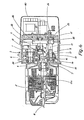
- Fig. 1 einen Elektrokettenzug gemäss der Erfindung in einer Schnittdarstellung und einer Seitenansicht;
- Fig. 2 den Elektrokettenzug nach Fig. 1, geschnitten längs der Linie 11-11 der Fig. 1 in einer Seitenansicht;
- Fig. 3 den Elektrokettenzug nach Fig. 1 in einer Ansicht des Getriebegehäuses bei abgenommenem Getriebedeckel gemäss der Linie 111-111 der Fig. 1, und
- Fig. 4 den Elektrokettenzug nach Fig. 1, geschnitten längs der Linie IV-IV der Fig. 2 in einer Draufsicht.
- Der Elektrokettenzug weist ein Getriebegehäuse 1 auf, an dem eine Aufhängeeinrichtung in Gestalt einer Aufhängeöse 2 befestigt ist und das auf zwei Seiten ein mit der Aufhängeöse 2 in einer gemeinsamen Vertikalebene liegendes Kettenrad 4 umschliesst, welches über ein in dem Getriebegehäuse 1 angeordnetes Stirnrad-Untersetzungsgetriebe 3 angetrieben ist. Seitlich an das Getriebegehäuse 1 ist ein als Bremsmotor ausgebildeter Elektromotor 5 mittels eines an seinem abtriebsseitigen Lagerschild 6 ausgebildeten Flansches 7 angeflanscht. Die Motorwelle 8 trägt ein Abtriebsritzel 9, das innerhalb des Getriebegehäuses 1 liegt und mit einem Zahnrad 10 der ersten Getriebestufe in Eingriff steht. Sie verläuft parallel zu der Achse 11 des Kettenrades 4.
- Wie insbesondere aus den Fig. 2 bis 4 zu ersehen, liegt das Kettenrad 4 auf einer Seite (in Fig. 2 auf der rechten Seite) des Abtriebsritzels 9 und der Motorwelle 8, während das mit dem Abtriebsritzel 9 in Eingriff stehende Zahnrad 10 der ersten Getriebestufe auf der gegenüberliegenden Seite des Abtriebsritzels 9 angeordnet ist und sowohl das Abtriebsritzel 9 als auch das Zahnrad 10 und das Kettenrad 4 in einer gemeinsamen Ebene liegen, die rechtwinklig zu der Motorwelle 8 verläuft und in Fig. 1 bei 11 angedeutet ist.
- Das Zahnrad 10 der ersten Getriebestufe ist frei drehbar auf einer Büchse 12 gelagert, die ihrerseits drehfest und axial verschieblich auf einer ersten Getriebewelle 13 sitzt, sowie mit einem Ringflansch 14 ausgebildet ist, der sich gegen ein die Getriebewelle 13 in einer entsprechenden Lagerausnehmung des Getriebegehäuses 1 lagerndes Wälzlager 15 abstützt. Der Ringflansch 14 trägt auf seiner dem Zahnrad 10 zugewandten Seite einen Reibbelag 16. Auf der gegenüberliegenden Seite ist auf die Getriebewelle 13 eine Kupplungsscheibe 17 ebenfalls drehfest und axial verschieblich aufgesetzt, die auch über einen Reibbelag 18 gegen das Zahnrad 10 abgestützt ist und gegen dieses durch Tellerfedern 19 angepresst wird, die endseitig an einem Ringbund der Getriebewelle 13 anliegen.
- Das Zahnrad 10 bildet somit mit dem Ringflansch 14 und der Kupplungsscheibe 17 eine Rutschkupplung, deren übertragbares maximales Drehmoment durch die Vorspannung der Tellerfedern 19 bestimmt ist. Um diese Vorspannung verändern zu können, ist die Getriebewelle 13 bezüglich des einen gehäusefesten Anschlag für den Ringflansch 14 bildenden Wälzlagers 15 axial verstellbar. Zu diesem Zwecke ist die Getriebewelle 13 andernends über ein Wälzlager 21 in einer entsprechenden Lagerausnehmung eines lösbar auf das Getriebegehäuse 1 aufgesetzten Getriebedeckels 22 gelagert, wobei die Anordnung derart getroffen ist, dass das Wälzlager 21 über eine Druckplatte 23 und eine in eine entsprechende Gewindebohrung des Getriebedeckels 22 eingeschraubte Stellschraube 24 axial verschiebbar ist. Die Stellschraube 24 ist ersichtlich von der Getriebeaussenseite her zugängig, so dass das Überlast-Drehmoment der Rutschkupplung bequem eingestellt werden kann.
- Auf der Getriebewelle 13 sitzt drehfest ein Zahnrad 25, das mit einem bei 27, 28 drehbar gelagerten Zahnrad 26 der zweiten Getriebestufe in Eingriff steht, welches seinerseits über ein drehfest mit ihm verbundenes Zahnrad 29 und ein auf die Welle 30 des Kettenrades 4 aufgekeiltes Zahnrad 31 der dritten Getriebestufe das Kettenrad 4 antreibt.
- Wie insbesondere aus Fig. 2, 3 zu entnehmen, liegen die Achsen der Motorwelle 8, der Getrieberäder 10, 25, 26, 29 und 31 und des Kettenrades 4 in einer gemeinsamen horizontalen Ebene, die in Fig. 2 bei 33 angedeutet ist. Damit ergibt sich eine extrem niedrige Bauhöhe des ganzen Getriebes.
- An dem Getriebegehäuse 1 ist die bei 34 angedeutete Kette endseitig verankert. Sie ist sodann, was nicht weiter veranschaulicht ist, über eine den Hubhaken tragende Flansche und das Kettenrad 4 geführt.
- Anstelle des Kettenrades 4 kann ohne Änderung der Gesamtkonstruktion auch eine kleine Seil-oder Bandtrommel erforderlichenfalls verwendet werden, weil nach Lösen der Schrauben 35,36 die seitlichen Kettenführungen 37, 38 einfach abgenommen werden können, was dadurch möglich ist, dass das Getriebegehäuse 1 das Kettenrad 4 lediglich auf zwei Seiten umgibt.
- Der Elektromotor 5 ist, wie erwähnt, ein einfacher Bremsmotor mit einem Abtriebsritzel 9 und einem Flansch 7 an seinem Lagerschild 6. Er kann in dieser Ausführungsform auch für andere Einsatzzwecke verwendet werden. Auch ist es möglich, zur Erzielung einer unterschiedlichen Hubgeschwindigkeit einen anderen Elektromotor 5 an das Getriebegehäuse 1 anzubauen, ohne dass dadurch an dem Getriebegehäuse 1 Änderungen erforderlich würden. Dies ist in Fig. 4 veranschaulicht, wo unterhalb der Achse der Motorwelle 8 alternativ ein anders gestalteter Elektromotor 5a angedeutet ist.
- Die erläuterte sehr geringe Bauhöhe des Getriebes und damit auch das Getriebegehäuse 1 ermöglicht es in der insbesondere aus den Fig. 1 und 3 ersichtlichen Weise den oberhalb und unterhalb des Getriebegehäuses 1 liegenden Raum auszunutzen. Zu diesem Zwecke ist das eigentliche Getriebegehäuse 1 von einem dem Umriss des Lagerschildes 6 folgenden und dieses fortsetzenden Gehäuseteil 39 umgeben, das endseitig durch eine aufgesetzte einfache Blechhaube 40 abgeschlossen ist. Zwischen dem Getriebegehäuse 1 und dem Gehäuseteil 39 ist ein freier Raum 41 vorhanden, in den Anschlussleitungen und Steuerleitungen 42 bzw. 43 eingeführt sind, die zu dem Elektromotor 5 oder zu Schalt- und Steuereinrichtungen führen, welche in dem Raum 41 untergebracht sind. Der sie enthaltende Geräteraum ist nach aussen hin durch die Haube 40 abgeschlossen.
Claims (1)
- Elektrokettenzug, dessen zwischen dem Abtriebsritzel (9) des Elektromotors (5) und dem dazu achsparallelen Kettenrad (4) liegendes, eine Überlast-Rutschkupplung enthaltendes Untersetzungsgetriebe (3) in einem Getriebegehäuse (1) angeordnet ist, das mit dem aussen angeflanschten Elektromotor zu einer eine Aufhänge- oder Befestigungseinrichtung (2) aufweisenden Baueinheit verbunden ist, in der das Kettenrad in unmittelbarer Nähe des Motorflansches (7) auf einer Seite des Abtriebsritzels angeordnet ist, wobei die Überlast-Rutschkupplung ein auf einer Getriebewelle (13) des Untersetzungsgetriebes drehbar gelagertes, angetriebenes Zahnrad (10) aufweist, das über mit der Getriebewelle drehfest verbundene Kupplungselemente (Kupplungsscheiben 14,17) reibschlüssig mit der Getriebewelle gekuppelt ist, die über ein Stellorgan (24) zum Nachstellen von aussen her bezüglich eines gehäusefesten Anschlages (Wälzlager 15) axial verschiebbar ist, dadurch gekennzeichnet, dass die Kupplungselemente aus beidseitig vom Zahnrad (10) angeordneten, axial verschieblichen Kupplungsscheiben (14, 17) bestehen, die auf ihrer dem Zahnrad zugewandten Seite einen Reibbelag (16) aufweisen, dass das Zahnrad über die Kupplungsscheiben mit der Getriebewelle (13) durch wenigstens ein ebenfalls auf der Getriebewelle angeordnetes Federelement (19) axial verspannt ist, dass die Abstützung der Getriebewelle in Vorspannrichtung über ein Lager (21) der Getriebewelle und eine Druckplatte (23) gegen eine als Stellorgan dienende Stellschraube (24) erfolgt und dass das Zahnrad einer ersten Getriebestufe des Untersetzungsgetriebes (3) zugeordnet ist.
Priority Applications (1)
| Application Number | Priority Date | Filing Date | Title |
|---|---|---|---|
| AT82107167T ATE17699T1 (de) | 1981-10-27 | 1982-08-07 | Elektrokettenzug. |
Applications Claiming Priority (2)
| Application Number | Priority Date | Filing Date | Title |
|---|---|---|---|
| DE19813142473 DE3142473A1 (de) | 1981-10-27 | 1981-10-27 | Elektrokettenzug |
| DE3142473 | 1981-10-27 |
Publications (3)
| Publication Number | Publication Date |
|---|---|
| EP0077890A2 EP0077890A2 (de) | 1983-05-04 |
| EP0077890A3 EP0077890A3 (en) | 1983-06-22 |
| EP0077890B1 true EP0077890B1 (de) | 1986-01-29 |
Family
ID=6144878
Family Applications (1)
| Application Number | Title | Priority Date | Filing Date |
|---|---|---|---|
| EP82107167A Expired EP0077890B1 (de) | 1981-10-27 | 1982-08-07 | Elektrokettenzug |
Country Status (3)
| Country | Link |
|---|---|
| EP (1) | EP0077890B1 (de) |
| AT (1) | ATE17699T1 (de) |
| DE (1) | DE3142473A1 (de) |
Families Citing this family (11)
| Publication number | Priority date | Publication date | Assignee | Title |
|---|---|---|---|---|
| DE3442791A1 (de) * | 1984-11-23 | 1986-06-12 | Wolfgang Dipl.-Ing. 8399 Ruhstorf Rösch | Elektronischer aufzugantrieb |
| DE3710332C1 (de) * | 1987-03-28 | 1988-07-21 | Stahl R Foerdertech Gmbh | Elektrozug |
| DE3911292A1 (de) * | 1989-04-04 | 1990-10-11 | Mannesmann Ag | Kompakthebezeug |
| DE3939976C1 (en) * | 1989-12-02 | 1991-04-11 | Abus Werner Buehne Kg, 5270 Gummersbach, De | Load lifter for small hoist - has impeller vane on DC motor shaft on end facing toward horn gear drive, in order to extract heat generated by motor |
| DE59303780D1 (de) * | 1993-10-06 | 1996-10-17 | Abus Kransysteme Gmbh & Co Kg | Vorrichtung zum Antrieb eines Hebezeugs |
| DE4408578C2 (de) * | 1994-03-14 | 1999-12-30 | Stahl R Foerdertech Gmbh | Sicherheitskupplung für einen Kettenzug |
| DE19508833C2 (de) * | 1994-03-14 | 1999-12-23 | Stahl R Foerdertech Gmbh | Kettenzug mit geschütztem Anschlußkasten |
| DE4434373C2 (de) * | 1994-09-15 | 1999-04-01 | Mannesmann Ag | Elektrozug mit drehzahlgeregelter Geschwindigkeit |
| DE19530891C2 (de) * | 1995-08-14 | 1999-11-18 | Mannesmann Ag | Hebezeug, das mit einem Zugmittel betrieben ist |
| DE19810994C1 (de) * | 1998-03-13 | 1999-08-19 | Hoffmann Foerdertechnik Gmbh W | Kettenhalterung für die Hubkette von Kettenzügen |
| DE10034950B4 (de) * | 2000-07-13 | 2009-02-12 | Hoffmann Fördertechnik GmbH Wurzen | Kettenbefestigung für die Rundstahlkette von Kettenzügen |
Family Cites Families (15)
| Publication number | Priority date | Publication date | Assignee | Title |
|---|---|---|---|---|
| FR657252A (fr) * | 1927-07-20 | 1929-05-21 | Palan coaxial à commande électrique | |
| US2022049A (en) * | 1932-06-30 | 1935-11-26 | Associated Electric Lab Inc | Signaling apparatus |
| US2656150A (en) | 1951-12-06 | 1953-10-20 | Yale & Towne Mfg Co | Hoist construction |
| GB741063A (en) | 1952-10-17 | 1955-11-23 | Demag Zug Gmbh | Electric hoist |
| DE967900C (de) * | 1952-10-18 | 1957-12-27 | Demag Zug Gmbh | Kleinsthebezeug |
| GB751023A (en) * | 1954-01-21 | 1956-06-27 | Columbus Mckinnon Chain Corp | Improvements in or relating to hoists |
| US2969954A (en) * | 1958-01-30 | 1961-01-31 | Columbus Mckinnon Corp | Electric hoist |
| DE1851340U (de) | 1959-06-24 | 1962-05-10 | King Ltd Geo W | Kettenzug. |
| DE1209711B (de) * | 1962-04-07 | 1966-01-27 | Demag Zug Gmbh | Kleinkettenflaschenzug mit Verschiebelaeufermotor |
| US3362685A (en) * | 1965-05-18 | 1968-01-09 | Paul R. Noye | Chain hoist |
| FR92370E (fr) * | 1966-11-22 | 1968-10-31 | Birfield Eng Ltd | Palan électrique |
| DE1431962A1 (de) * | 1967-01-20 | 1969-05-29 | Hoffmann & Co Kg | Durch einen Elektromotor angetriebene Kettenwinde |
| JPS5227808Y2 (de) * | 1973-05-14 | 1977-06-24 | ||
| US3971971A (en) * | 1974-11-15 | 1976-07-27 | Ingersoll-Rand Company | Electric hoist control and braking system |
| JPS5842119B2 (ja) * | 1976-04-02 | 1983-09-17 | 株式会社日立製作所 | 巻上機械用過負荷防止装置 |
-
1981
- 1981-10-27 DE DE19813142473 patent/DE3142473A1/de active Granted
-
1982
- 1982-08-07 AT AT82107167T patent/ATE17699T1/de active
- 1982-08-07 EP EP82107167A patent/EP0077890B1/de not_active Expired
Also Published As
| Publication number | Publication date |
|---|---|
| DE3142473C2 (de) | 1988-01-07 |
| ATE17699T1 (de) | 1986-02-15 |
| EP0077890A2 (de) | 1983-05-04 |
| EP0077890A3 (en) | 1983-06-22 |
| DE3142473A1 (de) | 1983-05-11 |
Similar Documents
| Publication | Publication Date | Title |
|---|---|---|
| DE69509265T3 (de) | Vorrichtung in einem Aufzugsübergeschwindigkeitsbegrenzer | |
| DE3900075C2 (de) | ||
| EP0190241B1 (de) | Mahlspaltverstellvorrichtung für müllereiwalzenstühle | |
| EP0077890B1 (de) | Elektrokettenzug | |
| EP0383915A1 (de) | Elektrischer antrieb mit zusätzlichem handantrieb | |
| EP2699355A2 (de) | Zentrifuge und verfahren zur überwachung eines drehmoments | |
| DE882373C (de) | Antriebstrommel, insbesondere fuer Bandfoerderer | |
| CH636319A5 (de) | Haspel zum abwickeln von baendern oder straengen. | |
| EP1400483B1 (de) | Kettenzug | |
| DE102007041878A1 (de) | Verfahren und Rollenmühle zur Zerkleinerung von Mahlgut | |
| EP0229122B1 (de) | Kettenwirkmaschine | |
| EP0045867B2 (de) | Regeleinrichtung für einen Kompressor zum Betrieb in Kraftfahrzeugen | |
| DE3320037C1 (de) | Walzenschüsselmühlengetriebe | |
| EP0729913B1 (de) | Kettenzug mit auf beide Seiten der Kupplung wirkender Bremse | |
| DE60200199T2 (de) | Bremssystem | |
| EP2769123A1 (de) | Lamellensperre mit differenzialgehäuse | |
| DE3048532A1 (de) | Reibungsdaempfer fuer die abstuetzung einer bewegten vorrichtung | |
| DE19537249B4 (de) | Antriebssystem zur Leistungsübertragung von einer Antriebsquelle auf mehrere Abtriebsstränge | |
| CH624745A5 (en) | Clutch, in particular for small electric hoists | |
| DE9204156U1 (de) | Stellantrieb für Lichtkuppeln o.dgl. | |
| DE3342172C2 (de) | Elektrischer Fahrantrieb für einen Kran oder das Fahrwerk eines Hubwerkes etc. | |
| DE2363691C2 (de) | Axialhubgerät mit motorisch angetriebenem Spindeltrieb | |
| DE19542565A1 (de) | Sicherungsvorrichtung für einen Rolladen oder ein Rolltor | |
| DE69024824T2 (de) | Mechanismus für Rücklaufverhinderung in beiden Drehrichtungen | |
| DE411457C (de) | Vorrichtung zur Regelung des mechanischen Zuges einer zwischen der Zugmaschine von Maschinenpfluegen o. dgl. und der Stromquelle befindlichen elektrischen Leitung |
Legal Events
| Date | Code | Title | Description |
|---|---|---|---|
| PUAI | Public reference made under article 153(3) epc to a published international application that has entered the european phase |
Free format text: ORIGINAL CODE: 0009012 |
|
| PUAL | Search report despatched |
Free format text: ORIGINAL CODE: 0009013 |
|
| AK | Designated contracting states |
Designated state(s): AT BE CH FR GB IT LI LU NL SE |
|
| AK | Designated contracting states |
Designated state(s): AT BE CH FR GB IT LI LU NL SE |
|
| 17P | Request for examination filed |
Effective date: 19830720 |
|
| GRAA | (expected) grant |
Free format text: ORIGINAL CODE: 0009210 |
|
| AK | Designated contracting states |
Designated state(s): AT BE CH FR GB IT LI LU NL SE |
|
| REF | Corresponds to: |
Ref document number: 17699 Country of ref document: AT Date of ref document: 19860215 Kind code of ref document: T |
|
| ITF | It: translation for a ep patent filed | ||
| ET | Fr: translation filed | ||
| PG25 | Lapsed in a contracting state [announced via postgrant information from national office to epo] |
Ref country code: LU Free format text: LAPSE BECAUSE OF NON-PAYMENT OF DUE FEES Effective date: 19860831 |
|
| PLBE | No opposition filed within time limit |
Free format text: ORIGINAL CODE: 0009261 |
|
| STAA | Information on the status of an ep patent application or granted ep patent |
Free format text: STATUS: NO OPPOSITION FILED WITHIN TIME LIMIT |
|
| 26N | No opposition filed | ||
| PGFP | Annual fee paid to national office [announced via postgrant information from national office to epo] |
Ref country code: GB Payment date: 19930721 Year of fee payment: 12 |
|
| PGFP | Annual fee paid to national office [announced via postgrant information from national office to epo] |
Ref country code: AT Payment date: 19930805 Year of fee payment: 12 |
|
| PGFP | Annual fee paid to national office [announced via postgrant information from national office to epo] |
Ref country code: SE Payment date: 19930817 Year of fee payment: 12 |
|
| PGFP | Annual fee paid to national office [announced via postgrant information from national office to epo] |
Ref country code: FR Payment date: 19930819 Year of fee payment: 12 |
|
| PGFP | Annual fee paid to national office [announced via postgrant information from national office to epo] |
Ref country code: CH Payment date: 19930827 Year of fee payment: 12 |
|
| ITTA | It: last paid annual fee | ||
| PGFP | Annual fee paid to national office [announced via postgrant information from national office to epo] |
Ref country code: NL Payment date: 19930831 Year of fee payment: 12 |
|
| PGFP | Annual fee paid to national office [announced via postgrant information from national office to epo] |
Ref country code: BE Payment date: 19930906 Year of fee payment: 12 |
|
| PG25 | Lapsed in a contracting state [announced via postgrant information from national office to epo] |
Ref country code: GB Effective date: 19940807 Ref country code: AT Effective date: 19940807 |
|
| PG25 | Lapsed in a contracting state [announced via postgrant information from national office to epo] |
Ref country code: SE Effective date: 19940808 |
|
| PG25 | Lapsed in a contracting state [announced via postgrant information from national office to epo] |
Ref country code: LI Effective date: 19940831 Ref country code: CH Effective date: 19940831 Ref country code: BE Effective date: 19940831 |
|
| EAL | Se: european patent in force in sweden |
Ref document number: 82107167.7 |
|
| BERE | Be: lapsed |
Owner name: R.STAHL G.M.B.H. & CO. ELEKTROZUGWERK Effective date: 19940831 |
|
| PG25 | Lapsed in a contracting state [announced via postgrant information from national office to epo] |
Ref country code: NL Effective date: 19950301 |
|
| GBPC | Gb: european patent ceased through non-payment of renewal fee |
Effective date: 19940807 |
|
| NLV4 | Nl: lapsed or anulled due to non-payment of the annual fee | ||
| PG25 | Lapsed in a contracting state [announced via postgrant information from national office to epo] |
Ref country code: FR Effective date: 19950428 |
|
| REG | Reference to a national code |
Ref country code: CH Ref legal event code: PL |
|
| EUG | Se: european patent has lapsed |
Ref document number: 82107167.7 |
|
| REG | Reference to a national code |
Ref country code: FR Ref legal event code: ST |