EP0074471A2 - Verfahren zum Herstellen von Wärmetauschern aus keramischen Folien - Google Patents
Verfahren zum Herstellen von Wärmetauschern aus keramischen Folien Download PDFInfo
- Publication number
- EP0074471A2 EP0074471A2 EP82105905A EP82105905A EP0074471A2 EP 0074471 A2 EP0074471 A2 EP 0074471A2 EP 82105905 A EP82105905 A EP 82105905A EP 82105905 A EP82105905 A EP 82105905A EP 0074471 A2 EP0074471 A2 EP 0074471A2
- Authority
- EP
- European Patent Office
- Prior art keywords
- foils
- cards
- heat exchanger
- ceramic
- flow channels
- Prior art date
- Legal status (The legal status is an assumption and is not a legal conclusion. Google has not performed a legal analysis and makes no representation as to the accuracy of the status listed.)
- Granted
Links
Images


Classifications
-
- F—MECHANICAL ENGINEERING; LIGHTING; HEATING; WEAPONS; BLASTING
- F28—HEAT EXCHANGE IN GENERAL
- F28F—DETAILS OF HEAT-EXCHANGE AND HEAT-TRANSFER APPARATUS, OF GENERAL APPLICATION
- F28F21/00—Constructions of heat-exchange apparatus characterised by the selection of particular materials
- F28F21/04—Constructions of heat-exchange apparatus characterised by the selection of particular materials of ceramic; of concrete; of natural stone
-
- Y—GENERAL TAGGING OF NEW TECHNOLOGICAL DEVELOPMENTS; GENERAL TAGGING OF CROSS-SECTIONAL TECHNOLOGIES SPANNING OVER SEVERAL SECTIONS OF THE IPC; TECHNICAL SUBJECTS COVERED BY FORMER USPC CROSS-REFERENCE ART COLLECTIONS [XRACs] AND DIGESTS
- Y10—TECHNICAL SUBJECTS COVERED BY FORMER USPC
- Y10T—TECHNICAL SUBJECTS COVERED BY FORMER US CLASSIFICATION
- Y10T156/00—Adhesive bonding and miscellaneous chemical manufacture
- Y10T156/10—Methods of surface bonding and/or assembly therefor
- Y10T156/1052—Methods of surface bonding and/or assembly therefor with cutting, punching, tearing or severing
- Y10T156/1062—Prior to assembly
Definitions
- the invention relates to a method for producing heat exchangers by means of foil technology, in that foils are shaped, stacked, laminated and fired, and to a device for constructing such a heat exchanger from individual foils.
- a process for the production of heat exchangers from ceramic foils is already known from DE-OS 28 41 571 by stacking foils punched out between two base plates with spacers and additionally milling so-called windows into the top wall. Such a block-shaped heat exchanger is then subjected to a cold or hot lamination process. Although such a process entails higher manufacturing costs than the conventional extrusion of ceramic heat exchangers, very thin walls are obtained. On the other hand, with the extrusion technique, it is not possible to install so-called baffles transverse to the direction of the flow channels. Also handling the Assembly of such heat exchangers from rods and thin-walled foils is very difficult and, moreover, the production method is very labor-intensive.
- the defects that have occurred in the described method do not allow rational mass production.
- the heat exchangers often have an inhomogeneous structure after their completion.
- heat exchangers made of silicon nitride show that the flow behavior is not optimal, since the porous surface of the silicon nitride does not result in smooth flow channels.
- the invention is therefore based on the object of specifying a method which eliminates the abovementioned shortcomings and also considerably reduces the manufacturing outlay, thereby making it possible to automate the manufacturing process. It is important to maintain an easily editable, error-free, dimensionally accurate and homogeneous ceramic heat exchanger. Furthermore, a suitable device for building a heat exchanger from individual foils is to be created for carrying out the method.
- the slip consists of a ceramic powder, organic binder, dispersing or thinning agent and, if necessary, plasticizers and other auxiliaries in the form of oils.
- the main starting point is silicon slip, to which 3 to 10% by weight of cordierite is preferably added.
- Other ceramic powder composed of cordierite having a composition of 9-20 wt .-% MgO, 30 to 50 wt .-% A l 2 0 3 and 41 to 57 wt .-% Si0. 2 Silicon carbide is also suitable, the mixture consisting of 70 to 92% by weight of SiC and 8 to 30% by weight of C.
- semiconducting barium titanates can be used if the heat exchanger block is also to be used as a heating element by applying electrical current to it.
- the organic binder per se is not subject to any particular restriction provided that a good bond to the ceramic powder is guaranteed and the required toughness and dimensional stability are present in the film, if necessary in combination with the plasticizer.
- Polyvinyl acetates and polyvinyl butyral have proven particularly successful.
- Water or organic solvents such as ethanol, toluene and trichlorethylene are used as dispersants and diluents.
- Frame formulations which are particularly suitable according to the invention for the production of the ceramic films are given below, the slip formulations being broken down into ceramic raw materials and binders or solvents:
- the viscosity of the slip can be influenced in particular by the solvent content. It has also been found that the use of ultrasound in the treatment of the casting slip is particularly advantageous. This treatment gives a casting slip with greater homogeneity, better casting properties and a maximum content of solids, which has a particular effect on the bulk density of the film. In this way, films with a higher packing density and improved mechanical properties can be obtained. Furthermore, it makes sense to provide a vibrating device on the casting belt that compresses the casting slip again or enables a uniform film thickness over the entire range.
- the ceramic films are brought to their final dimensions after lamination. If thick foils or very high flow channels are required, which go beyond the foil thickness of 0.1 to 1.5 mm, the foils are connected to individual cards with a lamination aid in a pre-lamination process. Various flow channels are then punched out of these foils or cards or the foil is subjected to an embossing process. In the latter case, the ceramic foils are exposed in matrices at 20 to 120 ° C and pressures of 5 to 100 bar, which results in comb-like projections.
- the punched or embossed cards are then built up by means of the device according to the invention to form a heat exchanger block, with which the individual layers are laminated together with the aid of a laminating press.
- a press device In the lamination process, a press device is used at pressures of 0.1 to 15 bar, preferably 1 bar and time intervals of 1 to 10 seconds. Normally, work is carried out at room temperature, but temperatures up to 100 ° C. can also be used. In individual cases, the pressure used depends on the organic content and the type of lamination aid.
- a paste is used, which preferably contains a ceramic filler, or a purely organic adhesive, which is applied by screen printing, spraying or rolling.
- the use of lamination aids has several advantages. On the one hand, low pressures are made possible during the lamination process, whereby deformation of the flow channels is avoided. Furthermore, the ripple of the foils is compensated and finally the lamination aid effectively reduces the lamination errors.
- the organic components are then heated up to 40 to 60% of the plastic content, which results in an additional raw strength. This also ensures that the heat exchanger block is easy to machine without the tools smearing through the organic components of the ceramic film.
- the remaining organic components are then heated and the heat exchanger block sintered between 1200 and 1700 ° C. It may still be necessary to rework the inlet and outlet openings of the flow channels in order to maintain a good connection to the various supply and discharge media.
- the invention further relates to a device for carrying out the method according to the invention.
- a device for carrying out the method according to the invention is a combined molding, laminating aid application and laminating device.
- Films or pre-laminated cards are subjected to a shaping to form the flow channels.
- the cards are brought to the application device for the laminating aid by means of suction plates which can be moved horizontally and vertically and swiveled by 180 °.
- the suction plate then swivels from this device to the laminating press and there deposits the differently shaped cards alternately, as a result of which the heat exchanger block is built up.
- the stack of cards thus obtained is subjected to a pressure.
- the method enables extensive automation, in particular through the device according to the invention, since in the previous production, due to the individual handling during punching, positioning and laminating, no continuous work process could be carried out.
- heat exchangers are also obtained which are very homogeneous and show very good contact between the individual layers after sintering.
- the improved method also results in better quality heat exchangers and so-called baffles can be installed transversely to the flow device of the channels without great effort.
- the baffles can be freely selected and are no longer dependent on the manufacturing process.
- Another possibility provides that curved flow channels can be produced. This means that asymmetrical and cylindrical heat exchangers can also be manufactured.
- heat exchangers can be obtained, which optionally consist of layers of silicon nitride, silicon carbide and cordierite in the form plates or foils are made according to DE-OS 26 31 092.
- FIG. 1 shows the manufacturing process of a gas / liquid heat exchanger made of silicon nitride.
- silicon powder with 24% by weight of ethanol, 10% by weight of toluene, 1.5% by weight of Menhaden oil, 8% by weight of polyvinyl butyral and 5% by weight of plasticizer.
- -% Palatinol and / or Ucon-Oil added to produce the ceramic casting slip.
- This mixture is ground in a drum mill with A1 2 0 3 balls for 20 hours and the slip is then evacuated.
- the usual warping of the slip for film production takes place on a steel belt.
- the slip is added above a casting shoe, the film thickness being determined by an adjustable gap height of 0.2 to 1.5 mm on the casting shoe.
- the film is then pulled off the steel strip and separated. It has proven to be expedient to construct so-called prelaminates from two to three foils.
- the individual foils are connected to one another by spraying or by applying a laminating aid.
- a paste is used which consists, for example, of 65% by weight of silicon and / or cordierite or of mixtures thereof.
- the paste also contains 20 to 40% by weight of unsaturated alcohols and 3 to 10% by weight of binder which contain plasticizers and polyvinyl butyral.
- the paste is printed using the screen printing process. At the same time, the unevenness of the surface is compensated for by the solid content of the paste.
- the paste also dissolves the surface, which later leads to homogeneous connections of the individual layers.
- the flue gas ducts 3 have a width of 50 mm and the walls 4 have a width of 3 to 7 mm. While a width of 100 mm has been chosen for the punched-out water pockets 5 and provided with baffles 6 perpendicular to the direction of flow, the card thickness here is 2.7 mm.
- the baffles are particularly intended to ensure that the temperature distribution is uniform in the flow channels.
- the heat exchanger block is assembled using the device according to the invention, as can be seen in FIG. 3.
- the suction plate 7 fetches cards 1, which simultaneously serve as covers between the cards 3 and 5 which are later punched out, from a stack of a magazine 8.
- the suction plate 7 then swivels through 180 ° and brings the card 1 under the screen printing device 9. Here it becomes Laminating aid applied.
- the suction plate 7 places the card on the lower part 10 of the laminating press 11 and returns to the magazine 8.
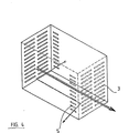
- a new card 1 is then fed to the punch 13. It is useful to have a punch I for the flue gas ducts 3 and the punch II for the water pockets 5 according to FIG. 4, which shows an assembled heat exchanger in which the edges 2 have been removed.
- the suction plate 7 now takes the punched card 3 and 5, and brings them to the Laminierstoffcited under the screen printing apparatus 9. After the screen printing operation, the suction plate 180 7um pivoted 0 and applied to the card 1 with light pressure. By alternately placing cards 1 on the punched cards 3 and 5, the heat exchanger block is stacked. The heat exchanger block thus finished is then in the Laminating press 11 pressed between the upper 12 and lower part 10, whereby the lamination process begins at the same time.
- the stacked heat exchanger block after having been removed from the laminating press, is subjected to a temperature treatment at temperatures between 100 and 200 ° C.
- the organic components especially the plasticizer and the lamination aid, evaporate.
- the heating process takes one to two days, with 40 to 60% of the organic components being expelled from the heat exchanger block.
- the heat exchanger block can be machined by milling or sawing, so that it obtains its final dimensions.
- the remaining organic constituents are then baked out at temperatures between 200 and 300 ° C. over a period of about 2 to 3 days. This measure eliminates the usual pre-sintering or pre-nitriding at 1100 to 1300 ° C, especially with silicon foils.
- the nitriding is then carried out in a known manner between 1300 and 1400 ° C.
- the tightness of the finished silicon heat exchanger can be increased by expediently replacing 3 to 10% by weight of silicon with cordierite in the lamination aid. This measure can also take place with the pouring slurry.
- post-sintering at temperatures between 1300 and 1400 ° C. is necessary, in the presence of oxygen, as is evident from DE-PS 25 44 437.
- the result of this process is a homogeneous, one-piece heat exchanger that is characterized by uniform strength.
Landscapes
- Engineering & Computer Science (AREA)
- Ceramic Engineering (AREA)
- Physics & Mathematics (AREA)
- Thermal Sciences (AREA)
- Mechanical Engineering (AREA)
- General Engineering & Computer Science (AREA)
- Heat-Exchange Devices With Radiators And Conduit Assemblies (AREA)
- Ceramic Products (AREA)
- Laminated Bodies (AREA)
- Producing Shaped Articles From Materials (AREA)
- Waste-Gas Treatment And Other Accessory Devices For Furnaces (AREA)
- Compositions Of Oxide Ceramics (AREA)
Abstract
Description
- Die Erfindung betrifft ein Verfahren zum Herstellen von Wärmetauschern mittels Folientechnik, indem Folien geformt, gestapelt, laminiert und gebrannt werden sowie eine Vorrichtung zum Aufbau eines solchen Wärmetauschers aus einzelnen Folien.
- Es ist bereits ein Verfahren zur'Herstellung von Wärmetauschern aus keramischen Folien aus der DE-OS 28 41 571 bekannt, indem zwischen zwei Grundplatten ausgestanzte Folien mit Abstandshaltern aufeinandergestapelt und zusätzlich sogenannte Fenster in die Deckwandung eingefräst werden. Anschließend wird ein solcher blockförmiger Wärmetauscher einem Kalt- oder Heißlaminierungsprozeß unterworfen. Ein solches Verfahren zieht zwar höhere Herstellungskosten gegenüber dem üblichen Strangziehen von keramischen Wärmetauschern nach sich, aber man erhält sehr dünne Wandungen. Andererseits ist mit der Strangziehtechnik kein Einbau von sogenannten Schikanen quer zur Ziehrichtung der Strömungskanäle möglich. Auch die Handhabung beim Zusammenbau solcher Wärmetauscher aus Stäben und dünnwandigen Folien ist sehr schwierig und außerdem ist die Herstellungsmethode sehr arbeitsaufwendig. Ferner hat sich beim Laminieren herausgestellt, daß nicht immer alle Folien gleichmäßig aufeinander haften und insbesondere verschmieren bei der Rohbearbeitung des ungesinterten Wärmetauscherblockes die Werkzeuge leicht durch den organischen Bindemittelgehalt der Folien. Entfernt man nun das gesamte Bindemittel aus der Keramik, so wird der Körper sehr spröde, so daß wiederum dieser sich schlecht bearbeiten läßt.
- Des weiteren ist aus der UK-PS 1,418,459 ein Verfahren bekannt, das die Herstellung von Wärmetauschern aus Folien vorsieht. Die Folien von etwa 0,15 mm Dicke werden auf einem verbrennbaren Trägermaterial mittels des Doctor-Blade-Verfahrens hergestellt, wobei sich als besonders nachteilig erwiesen hat; daß die Abstandshalter zwischen den Medientrennwänden in sehr aufwendigen und für eine Serienfertigung wenig geeigneten Technik erstellt werden. Der Aufbau des Wärmetauschers erfolgt durch abwechselndes Aufeinanderlegen von Silicium-Kunststoff-Folien und Abstandshaltern, die auf Gießfolien aufgebracht sind. Unter Verwendung von Druck und Temperatur als auch eines Lösungsmittels oder Klebers werden die einzelnen Teile des Wärmetauschers zusammengefügt. Beim Brennen muß zuerst das Papier entfernt werden, . dann der Binder und schließlich der Nitridierungsprozeß durchgeführt werden. Beim Verbrennen des Papiers muß außerdem sichergestellt werden, daß die feine Siliciumstruktur nicht beschädigt wird und die dabei gebildete Asche wird durch Ultraschallwaschen entfernt. Ferner ist vor dem Verbrennen des Papiers eine Teilnitridierung des Wärmetauscherblockes durchzuführen.
- Die aufgetretenen Mängel bei dem beschriebenen Verfahren erlauben keine rationelle Massenfertigung. Auch weisen die Wärmetauscher nach ihrer Fertigstellung oft ein inhomogenes Gefüge auf. Insbesondere zeigt sich bei Wärmetauschern aus Siliciumnitrid, daß das Strömungsverhalten nicht optimal ist, da'durch die poröse Oberfläche des Siliciumnitrids man keine glatten Strömungskanäle erhält.
- Der Erfindung liegt deshalb die Aufgabe zugrunde, ein Verfahren anzugeben, das die genannten Mängel beseitigt als auch den Fertigungsaufwand erheblich verringert und eben dadurch eine Automatisierung des Herstellungsprozesses möglich macht. Dabei wird Wert darauf gelegt, einen leicht bearbeitbaren, fehlerfreien, maßgenauen und homogenen Wärmetauscher aus Keramik zu erhalten. Ferner soll zur Durchführung des Verfahrens eine geeignete Vorrichtung zum Aufbau eines Wärmetauschers aus einzelnen Folien geschaffen werden.
- Diese Aufgabe wird erfindungsgemäß durch die im Hauptanspruch angegebenen Verfahrensschritte gelöst. Für die Herstellung der Folien werden übliche keramische Schlicker verwendet. Der Schlicker besteht aus einem keramischen Pulver, organischem Bindemittel, Dispergier- oder Verdünnungsmittel und ggf. Weichmachern sowie sonstigen Hilfsmitteln in Form von Ölen. Ausgegangen wird hauptsächlich von Siliciumschlickern, denen bevorzugt 3 bis 10 Gew.-% Cordierit zugegeben wird. Andere keramische Pulver bestehen aus Cordierit mit der Zusammensetzung von 9 bis 20 Gew.-% MgO, 30 bis 50 Gew.-% Al203 und 41 bis 57 Gew.-% Si02. Ferner eignet sich auch gut Siliciumcarbid, wobei die Mischung aus 70 bis 92 Gew.-% SiC und 8 bis 30 Gew.-% C besteht. Ferner können halbleitende Bariumtitanate verwendet werden, wenn der Wärmetauscherblock gleichzeitig als Heizelement einzusetzen ist, indem er mit elektrischem Strom beaufschlagt wird. Das organische Bindemittel unterliegt an sich keiner besonderen Beschränkung, sofern eine gute Bindung zum keramischen Pulver gewährleistet ist und bei der Folie ggf. in Kombination mit dem Weichmacher die erforderliche Zähigkeit und Maßhaltigkeit vorliegt. Insbesondere gut bewährt haben sich Polyvinylazetate und Polyvinylbutyral. Als Dispergierungs- und Verdünnungsmittel dienen Wasser oder organische Lösungsmittel wie zum Beispiel Äthanol, Toluol und Trichloräthylen. Erfindungsgemäß besonders geeigneter Rahmenrezepturen für die Herstellung der Keramikfolien sind nachfolgend angegeben, wobei die Schlickerrezepturen nach Keramikrohstoff- und Binde- bzw. Lösungsmitteln aufgeschlüsselt sind:

- Die Viskosität des Schlickers ist insbesondere durch den Lösungsmittelgehalt beeinflußbar. Auch hat sich herausgestellt, daß die Anwendung von Ultraschall bei der Aufbereitung des Gießschlickers besonders vorteilhaft ist. Durch diese Behandlung erhält man einen GieBschlicker mit größerer Homogenität, besseren Gießeigenschaften und einem maximalen Gehalt an Feststoffanteilen, was sich besonders auf die Rohdichte der Folie auswirkt. Auf diese Weise kann man Folien mit größerer Packungsdichte und verbesserten mechanischen Eigenschaften bekommen. Weiterhin ist es sinnvoll, am Gießband eine Vibrationsvorrichtung vorzusehen, die den Gießschlicker nochmals verdichtet bzw. eine gleichmäßige Folienstärke über die ganze Bandbreite ermöglicht.
- Nach diesem Verfahren werden die Keramikfolien nach dem Laminieren auf Endmaß gebracht. Werden dicke Folien bzw. sehr hohe Strömungskanäle verlangt, die über die Folienstärke von 0,1 bis 1,5 mm hinausgehen, so werden in einem Vorlaminierungsprozeß die Folien zu einzelnen Karten mit einem Laminierhilfsmittel verbunden. Aus diesen Folien bzw. Karten werden dann verschiedene Strömungskanäle ausgestanzt bzw. wird die Folie einem Prägeverfahren unterworfen. Im letzteren Fall werden die keramischen Folien in Matrizen bei 20 bis 120 °C und Drücken von 5 bis 100 bar ausgesetzt, wodurch kammartige Vorsprünge entstehen.
- Die ausgestanzten bzw. geprägten Karten werden dann mittels der erfindungsgemäßen Vorrichtung zu einem Wärmetauscherblock aufgebaut, mit der gleichzeitig das Zusammenlaminieren der Einzelschichten mit Hilfe einer Laminierpresse erfolgt.
- Bei dem Laminierungsvorgang verwendet man eine Pressvorrichtung bei Drücken von 0,1 bis 15 bar, vorzugsweise 1 bar und Zeitintervalle von 1 bis 10 sec. Normalerweise wird bei Raumtemperatur gearbeitet, aber auch Temperaturen bis zu 100 C sind anwendbar. Im einzelnen Fall richtet sich der angewendete Druck nach dem Organikgehalt und der Art des Laminierhilfsmittels. Für den Laminierungsvorgang benutzt man entweder eine Paste, die vorzugsweise einen keramischen Füllstoff enthält oder ein rein organisches Klebemittel, welche durch Siebdrucken, Sprayen oder Rollen aufgetragen werden. Die Anwendung von Laminierhilfsmittel bringt mehrere Vorteile mit sich. Zum einen werden niedrige Drücke beim Laminiervorgang ermöglicht, wodurch eine Verformung der Strömungskanäle vermieden wird. Weiterhin wird die Welligkeit der Folien ausgeglichen und schließlich verringert das Laminierhilfsmittel wirkungsvoll die Laminierfehler. Anschließend erfolgt das Ausheizen der organischen Bestandteile bis auf 40 bis 60 % des Kunststoffanteils, was eine zusätzliche Rohfestigkeit bewirkt. Damit wird auch erreicht, daß der Wärmetauscherblock gut bearbeitbar ist, ohne daß die Werkzeuge durch die organischen Bestandteile der keramischen Folie verschmieren. Danach erfolgt das Ausheizen der restlichen organischen Bestandteile und das Sintern des Wärmetauscherblockes zwischen 1200 bis 1700 °C. Eventuell ist noch ein Nachbearbeiten der Eingangs- und Austrittsöffnungen der Strömungskanäle notwendig, um einen guten Anschluß zu den verschiedenen zu- und abführenden Medien zu erhalten.
- Die Erfindung betrifft ferner eine Vorichtung zur Durchführung des erfindungsgemäßen Verfahrens. Im einzelnen handelt es sich um eine kombinierte Form-, Laminierhilfsmittelauftrags- und Laminiervorrichtung. Dabei werden Folien bzw. vorlaminierte Karten einer Formgebung zur Ausbildung der Strömungskanäle unterworfen. Mittels Saugplatten, die horizontal und vertikal bewegbar sowie um 180 ° schwenkbar sind, werden die Karten zur Auftragsvorrichtung für das Laminierhilfsmittel gebracht. Von dieser Vorrichtung schwenkt dann die Saugplatte zu der Laminierpresse und legt dort die unterschiedlich geformten Karten wechselweise ab, wodurch sich der Wärmetauscherblock aufbaut. Der so erhaltene Kartenstapel wird einem Preßdruck unterworfen.
- Das Verfahren ermöglicht insbesondere durch die erfindungsgemäße Vorrichtung eine weitgehende Automatisierung, da bei der bisherigen Herstellung durch die einzelne Handhabung beim Stanzen, Positionieren und Laminieren kein kontinuierlicher Arbeitsvorgang durchführbar war. Nach dem Verfahren der Erfindung erhält man auch Wärmetauscher, die sehr homogen sind und eine sehr gute Kontaktauflage zwischen den einzelnen Schichten nach dem Sintern zeigen. Mit dem verbesserten Verfahren ergeben sich auch qualitativ bessere Wärmetauscher und ohne größeren Aufwand können sogenannte Schikanen quer zur Strömungseinrichtung der Kanäle eingebaut werden. Die Schikanen sind frei wählbar und nicht mehr abhängig vom Herstellungsprozeß. Eine weitere Möglichkeit sieht vor, daß man gekrümmte Strömungskanäle herstellen kann. Somit sind auch unsymmetrische und zylinderförmige Wärmetauscher zu fertigen. Weiterhin kann man Wärmetauscher erhalten, die wahlweise aus Schichten von Siliciumnitrid, Siliciumcarbid und Cordierit in Form von Platten oder Folien bestehen gemäß der DE-OS 26 31 092. Durch diese Verwendung von Cordierit, insbesondere bei Siliciumnitrid erhält man glatte und damit widerstandsarme Strömungskanäle.
- Weitere Besonderheiten des erfindungsgemäßen Verfahrens sowie der erfindungsgemäßen Vorrichtung zum Aufbau des Wärmetauschers aus einzelnen Folien ergeben sich aus dem Beschreibungsbeispiel zur Herstellung eines solchen Wärmetauschers anhand der Zeichnungen. Es zeigen:
- Fig. 1: Verfahrensstammbaum des erfindungsgemäßen Verfahrens;
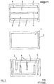
- Fig. 2: Draufsicht auf Karten mit und ohne verschiedenen ausgestanzten Strömungskanälen;
- Fig. 3: Erfindungsgemäße Vorrichtung zum Bau eines Wärmetauschers aus einzelnen Folien.
- Fig. 4: Die perspektivische Ansicht einer Ausführungsform, gemäß dem erfindungsgemäßen Verfahren.
- Die Fig. 1 zeigt das Herstellungsverfahren eines erfindungsgemäßen Gas/Flüssigkeits-Wärmetauschers aus Siliciumnitrid. Zur Herstellung des keramischen Gießschlickers werden 100 Gew.-% Siliciumpulver mit 24 Gew.-% Äthanol, 10 Gew.-% Toluol, 1,5 Gew.-% Menhaden-Oil, 8 Gew.-% Polyvinylbutyral und als Weichmacher 5 Gew.-% Palatinol und/oder Ucon-Oil zugegeben. Diese Mischung wird 20 Stunden in einer Trommelmühle mit A1203-Kugeln gemahlen und der Schlicker wird anschließend evakuiert. Das übliche Verziehen des Schlickers zur Folienherstellung erfolgt auf einem Stahlband. Die Schlickerzugabe geschieht über einem GieBschuh, wobei die Folienstärke durch eine einstellbare Spalthöhe von 0,2 bis 1,5 mm am GieBschuh bestimmt wird. Die Folie wird dann vom Stahlband abgezogen und vereinzelt. Dabei hat sich als zweckmäßig herausgestellt, sogenannte Vorlaminate aus zwei bis drei Folien aufzubauen. Die Verbindung der einzelnen Folien untereinander wird durch Aufsprayen bzw. durch Auftragen eines Laminierhilfsmittels erreicht. Im letzteren Fall verwendet man eine Paste, die beispielsweise aus 65 Gew.-% Silicium und/oder Cordierit bzw. aus Mischungen derselben besteht. In der Paste sind ferner 20 bis 40 Gew.-% ungesättigte Alkohole und 3 bis 10 Gew.-% Bindemittel, die Weichmacher und Polyvinylbutyral enthalten. Der Aufdruck der Paste erfolgt in diesem Fall im Siebdruckverfahren. Gleichzeitig wird durch den Feststoffgehalt der Paste die Oberflächenunebenheit ausgeglichen. Ebenfalls erfolgt ein oberflächiges Anlösen der Folien durch die Paste, was später zu homogenen Verbindungen der einzelnen Schichten führt. Bei der Verwendung von Siliciumfolien ist es sinnvoll, die Vorlaminate vollständig zu bedrucken, zumal wenn die Paste einen Cordieritbestandteil enthält, der mit dem späteren Siliciumnitrid im Sinterprozeß zur Ausschwitzung von einer Glasphase führt, was glatte und dichte Oberflächen der Strömungskanäle bewirkt. Ansonsten werden nur diejenigen Stellen bedruckt, die zur Verbindung der Folien notwendig sind. Damit wird erreicht, daß die ausgestanzten Teile wieder zurückgeführt und dem Gießschlicker beigesetzt werden können.
- In Fig. 2 sind die rechteckigen Folien bzw. Karten mit einer Dicke von 0,9 mm für den Aufbau eines Gasheizwärmetauschers zu sehen. Diese Karten 1 haben dabei Abmessungen von 12o mm x 400 mm und sind mit einem zusätzlichen Rand 2 versehen, der bei der späteren Nachbearbeitung entfernt wird. Bei den ausgestanzten Karten mit einer Stärke von 1,8 mm weisen die Rauchgaskanäle 3 eine Breite von 50 mm auf und die Wandungen 4 haben eine Breite von 3 bis 7 mm. Während für die ausgestanzten Wassertaschen 5 eine Breite von 100 mm gewählt worden ist und mit Schikanen 6 senkrecht zur Strömungsrichtung versehen sind, beträgt hier die Kartendicke 2,7 mm. Die Schikanen sollen insbesondere bewirken, daß die Temperaturverteilung gleichmäßig in den Strömungskanälen ist.
- Der Zusammenbau des Wärmetauscherblocks erfolgt mit Hilfe der erfindungsgemäßen Vorrichtung wie es sich aus Fig. 3 ergibt. Die Saugplatte 7 holt sich Karten 1, die gleichzeitig als Abdeckungen zwischen den später ausgestanzten Karten 3 und 5 dienen von einem Stapel aus einem Magazin 8. Die Saugplatte 7 schwenkt dann um 180 ° und bringt die Karte 1 unter die Siebdruckvorrichtung 9. Hier wird das Laminierhilfsmittel aufgebracht. Die Saugplatte 7 legt die Karte auf das Unterteil 10 der Laminierpresse 11 ab und kehrt zurück zum Magazin 8. Eine neue Karte 1 wird dann der Stanze 13 zugeführt. Zweckmäßigerweise hat man hier eine Stanze I für die Rauchgaskanäle 3 und die Stanze II für die Wassertaschen 5 gemäß der Fig. 4, die einen zusammengebauten Wärmetauscher zeigt, bei dem die Ränder 2 entfernt worden sind. Die Saugplatte 7 nimmt nun die ausgestanzte Karte 3 bzw. 5 und bringt sie für den Laminiermittelauftrag unter die Siebdruckvorrichtung 9. Nach erfolgtem Siebdruckvorgang wird die Saugplatte 7um 180 0 geschwenkt und mit leichtem Druck auf die Karte 1 aufgebracht. Durch das wechselweise Ablegen der Karten 1 auf die aufgestanzten Karten 3 und 5 wird der Wärmetauscherblock gestapelt. Der so fertig gestellte Wärmetauscherblock wird dann in der Laminierpresse 11 zwischen dem Ober- 12 und Unterteil 10 zusammengepreßt, wodurch gleichzeitig der Laminierprozeß einsetzt.
- Der gestapelte Wärmetauscherblock wird, nachdem er der Laminierpresse entnommen worden ist, bei Temperaturen zwischen 100 bis 200 °C einer Temperaturbehandlung unterworfen. Dabei verflüchtigen sich die organischen Bestandteile besonders der Weichmacher und das Laminierhilfsmittel. Der Ausheizvorgang dauert ein bis zwei Tage, wobei 40 bis 60 % der organischen Bestandteile aus dem Wärmetauscherblock ausgetrieben werden. Danach kann der Wärmetauscherblock gleichsam durch Fräsen oder Sägen bearbeitet werden, so daß er seine endgültigen Maße erhält. In einem Zeitraum von ca. 2 bis 3 Tagen wird dann der restliche Gehalt an organischen Bestandteilen bei Temperaturen zwischen 200 und 300 °C ausgeheizt. Durch diese Maßnahme entfällt insbesondere bei Siliciumfolien dann das übliche Vorsintern bzw. Vornitridierung bei 1100 bis 1300 °C. Die Nitridierung erfolgt dann in bekannter Weise zwischen 1300 bis 1400 °C. Wie schon erwähnt, kann man die Dichtigkeit der fertigen Silicium-Wärmetauscher noch erhöhen, indem man zweckmäßigerweise 3 bis 10 Gew.-% Silicium durch Cordierit beim Laminierhilfsmittel ersetzt. Diese Maßnahme kann auch beim Gießschlicker erfolgen. Dann ist jedoch ein Nachsintern bei Temperaturen zwischen 1300 bis 1400 °C notwendig, und zwar unter Anwesenheit von Sauerstoff, wie sich aus der DE-PS 25 44 437 ergibt. Das Ergebnis dieses Verfahrens ist ein homogener einstückiger Wärmetauscher, der sich durch eine gleichmäßige Festigkeit auszeichnet.
Claims (9)
Priority Applications (1)
| Application Number | Priority Date | Filing Date | Title |
|---|---|---|---|
| AT82105905T ATE11698T1 (de) | 1981-09-12 | 1982-07-02 | Verfahren zum herstellen von waermetauschern aus keramischen folien. |
Applications Claiming Priority (2)
| Application Number | Priority Date | Filing Date | Title |
|---|---|---|---|
| DE19813136253 DE3136253A1 (de) | 1981-09-12 | 1981-09-12 | Verfahren und vorrichtung zum herstellen von waermetauschern aus keramischen folien |
| DE3136253 | 1981-09-12 |
Publications (3)
| Publication Number | Publication Date |
|---|---|
| EP0074471A2 true EP0074471A2 (de) | 1983-03-23 |
| EP0074471A3 EP0074471A3 (en) | 1983-06-22 |
| EP0074471B1 EP0074471B1 (de) | 1985-02-06 |
Family
ID=6141507
Family Applications (1)
| Application Number | Title | Priority Date | Filing Date |
|---|---|---|---|
| EP82105905A Expired EP0074471B1 (de) | 1981-09-12 | 1982-07-02 | Verfahren zum Herstellen von Wärmetauschern aus keramischen Folien |
Country Status (5)
| Country | Link |
|---|---|
| US (1) | US4526635A (de) |
| EP (1) | EP0074471B1 (de) |
| JP (1) | JPS5860195A (de) |
| AT (1) | ATE11698T1 (de) |
| DE (2) | DE3136253A1 (de) |
Families Citing this family (19)
| Publication number | Priority date | Publication date | Assignee | Title |
|---|---|---|---|---|
| DE3213378C2 (de) * | 1982-04-10 | 1984-10-11 | Pacific Wietz Gmbh + Co Kg, 4600 Dortmund | Mehrschichtiger Gleitkörper und Verfahren zu seiner Herstellung |
| JPS6183897A (ja) * | 1984-09-28 | 1986-04-28 | Asahi Glass Co Ltd | セラミツクス製の熱交換体 |
| US4875712A (en) * | 1985-02-05 | 1989-10-24 | Asahi Glass Company, Ltd. | Joint structure for a tube support plate and a tube |
| US4838581A (en) * | 1985-02-05 | 1989-06-13 | Asahi Glass Company Ltd. | Joint structure for a tube support plate and a tube |
| DE3717670A1 (de) * | 1986-11-21 | 1988-06-01 | Hoechst Ceram Tec Ag | Verfahren zum abdichten keramischer waermetauscher |
| DE3643750A1 (de) * | 1986-12-20 | 1988-06-30 | Hoechst Ag | Waermetauschermodul aus gebranntem keramischen material |
| DE3643749A1 (de) * | 1986-12-20 | 1988-06-30 | Hoechst Ag | Waermetauschermodul aus gebranntem keramischen material |
| DE3719606A1 (de) * | 1987-06-12 | 1988-12-22 | Hoechst Ceram Tec Ag | Verfahren zur silicierung von poroesen formkoerpern aus siliciumcarbid oder siliciumcarbid/kohlenstoff |
| JPH0670941B2 (ja) * | 1988-12-15 | 1994-09-07 | 株式会社村田製作所 | 積層コンデンサの製造方法 |
| US5035961A (en) * | 1989-07-05 | 1991-07-30 | Combustion Engineering, Inc. | Internal cross-anchoring and reinforcing of multi-layer conductive oxides |
| DE4022654A1 (de) * | 1990-07-17 | 1992-01-23 | Hoechst Ag | Karte aus keramischem material zum aufbau von durchlaessigen strukturen |
| DE4100108C1 (en) * | 1991-01-04 | 1992-04-09 | Robert Bosch Gmbh, 7000 Stuttgart, De | Joining non-sintered ceramic film to further laminate - involves applying layer contg. solvent for binder of ceramic film to surface to be connected |
| WO1994002294A1 (de) * | 1992-07-15 | 1994-02-03 | Hoechst Ceramtec Aktiengesellschaft | Verfahren zum aufbauen strukturierter keramischer grünkörper |
| JP4239077B2 (ja) * | 2003-08-20 | 2009-03-18 | 独立行政法人 日本原子力研究開発機構 | 高温耐食性セラミックス製コンパクト熱交換器 |
| DE10361346A1 (de) * | 2003-12-16 | 2005-07-14 | Deutsches Zentrum für Luft- und Raumfahrt e.V. | Platten-Wärmeübertrager, Verfahren zur Herstellung eines Platten-Wärmeübertragers und keramischer Faserverbundwerkstoff, insbesondere für einen Platten-Wärmeübertrager |
| FR2905754B1 (fr) * | 2006-09-12 | 2008-10-31 | Boostec Sa Sa | Procede de fabrication d'un dispositif de type echangeur de chaleur en carbure de silicium et dispositif en carbure de silicium realise par le procede |
| DE102007048013A1 (de) * | 2007-09-27 | 2009-04-02 | Deutsches Zentrum für Luft- und Raumfahrt e.V. | Verfahren zur Herstellung eines keramischen Wärmeübertragers und keramischer Hochtemperatur-Wärmeübertrager |
| ES2531124B1 (es) * | 2013-09-10 | 2016-01-22 | Valeo Térmico, S. A. | Intercambiador de calor para gases, en especial de los gases de escape de un motor |
| US9696097B2 (en) * | 2014-08-01 | 2017-07-04 | Applied Materials, Inc. | Multi-substrate thermal management apparatus |
Family Cites Families (18)
| Publication number | Priority date | Publication date | Assignee | Title |
|---|---|---|---|---|
| US3358853A (en) * | 1965-10-11 | 1967-12-19 | Warner Swasey Co | Sheet handling device |
| US4202660A (en) * | 1970-04-22 | 1980-05-13 | Owens-Illinois, Inc. | Glass-ceramic article and method of making same |
| BE790158A (fr) * | 1971-12-21 | 1973-02-15 | Chausson Usines Sa | Dispositif pour l'empilage alterne d'ailettes de radiateurs et elementsanalogues de nature differente |
| GB1418459A (en) * | 1971-12-29 | 1975-12-17 | Atomic Energy Authority Uk | Sintered artefacts |
| GB1418663A (en) * | 1972-03-27 | 1975-12-24 | Atomic Energy Authority Uk | Refractory structures |
| US3943994A (en) * | 1972-12-07 | 1976-03-16 | Gte Sylvania Incorporated | Ceramic cellular structure having high cell density and method for producing same |
| US3854186A (en) * | 1973-06-14 | 1974-12-17 | Grace W R & Co | Method of preparing a heat exchanger |
| US3940301A (en) * | 1974-08-01 | 1976-02-24 | Caterpillar Tractor Co. | Method of manufacturing an open cellular article |
| DE2544437C3 (de) * | 1975-10-04 | 1979-04-05 | Rosenthal Ag, 8672 Selb | Verfahren zur Herstellung von silizhimnitridhaltigen mit einer Selbstglasur Überzogenen Gegenständen |
| US4156051A (en) * | 1975-11-10 | 1979-05-22 | Tokyo Shibaura Electric Co., Ltd. | Composite ceramic articles |
| DE2631092C2 (de) * | 1976-07-10 | 1982-02-04 | Rosenthal Technik Ag, 8672 Selb | Keramischer Wechselschicht-Wärmetauscher in Modulbauweise |
| US4130160A (en) * | 1976-09-27 | 1978-12-19 | Gte Sylvania Incorporated | Composite ceramic cellular structure and heat recuperative apparatus incorporating same |
| US4230651A (en) * | 1977-07-18 | 1980-10-28 | Ford Motor Company | Method of fabricating a heat exchanger for Stirling engine |
| DE2807755C3 (de) * | 1977-09-26 | 1982-03-18 | Tecfinor AG, Zürich | Verfahren zur Herstellung eines keramischen Körpers |
| JPS5839799B2 (ja) * | 1978-05-02 | 1983-09-01 | 日産自動車株式会社 | 大型ハニカム構造体の製造方法 |
| CA1121332A (en) * | 1978-09-01 | 1982-04-06 | Joseph J. Cleveland | Ceramic heat recuperative structure and assembly |
| US4298059A (en) * | 1978-09-23 | 1981-11-03 | Rosenthal Technik Ag | Heat exchanger and process for its manufacture |
| DE2841571C2 (de) * | 1978-09-23 | 1982-12-16 | Kernforschungsanlage Jülich GmbH, 5170 Jülich | Einflutiger keramischer Rekuperator und Verfahren zu seiner Herstellung |
-
1981
- 1981-09-12 DE DE19813136253 patent/DE3136253A1/de not_active Withdrawn
-
1982
- 1982-07-02 DE DE8282105905T patent/DE3262215D1/de not_active Expired
- 1982-07-02 AT AT82105905T patent/ATE11698T1/de active
- 1982-07-02 EP EP82105905A patent/EP0074471B1/de not_active Expired
- 1982-09-08 US US06/415,800 patent/US4526635A/en not_active Expired - Lifetime
- 1982-09-09 JP JP57156004A patent/JPS5860195A/ja active Granted
Also Published As
| Publication number | Publication date |
|---|---|
| JPH0219400B2 (de) | 1990-05-01 |
| US4526635A (en) | 1985-07-02 |
| ATE11698T1 (de) | 1985-02-15 |
| DE3136253A1 (de) | 1983-03-31 |
| EP0074471B1 (de) | 1985-02-06 |
| JPS5860195A (ja) | 1983-04-09 |
| EP0074471A3 (en) | 1983-06-22 |
| DE3262215D1 (en) | 1985-03-21 |
Similar Documents
| Publication | Publication Date | Title |
|---|---|---|
| EP0074471B1 (de) | Verfahren zum Herstellen von Wärmetauschern aus keramischen Folien | |
| DE10256980B4 (de) | Herstellverfahren für einen gestapelten keramischen Körper | |
| DE3941346C2 (de) | Verfahren und Vorrichtung zur Herstellung von Mehrschichtkondensatoren | |
| DE10240161B4 (de) | Keramikeinsatzplatte und Verfahren zu ihrer Herstellung | |
| EP0894340A1 (de) | Monolithischer vielschicht-piezoaktor und verfahren zur herstellung | |
| DE69031839T2 (de) | Geschichtete Keramikanordnung und Verfahren zur deren Herstellung | |
| EP0092716A1 (de) | Gleitkörper, Verfahren zu seiner Herstellung | |
| DE2227343B2 (de) | Harzmischung, keramische Paste und Verfahren zum Herstellen gesinterter, dielektrischer Keramikstrukturen | |
| DE2451236C2 (de) | Verfahren zum Herstellen keramischer Substrate | |
| EP0362213B1 (de) | Verfahren zur herstellung einer strukturierten keramikfolie bzw. eines aus solchen folien aufgebauten keramikkörpers | |
| DE2364242C2 (de) | Keramikplatten und ihre Verwendung | |
| DE102004026572A1 (de) | Herstellungsverfahren für piezoelektrisches Schichtelement | |
| DE2445086C2 (de) | Verfahren zur Herstellung eines für die Herstellung eines Kondensators geeigneten Keramikkörpers | |
| DE3619871C2 (de) | ||
| EP1273050B1 (de) | Verfahren und vorrichtung zur herstellung von mehrschicht-aktoren | |
| DE19643148C2 (de) | Herstellverfahren für keramische Körper mit Mikrostruktur und Verwendungen | |
| DE2737509A1 (de) | Verfahren zur herstellung von keramik-kondensatoren | |
| DE2420726B2 (de) | Verfahren und vorrichtung zur herstellung von presskoerpern mit schichtweise verschiedener zusammensetzung fuer hochbelastbare elektrische kontakte | |
| DE2717286C3 (de) | Verfahren zum Hersteilen einer mehrlagigen Leiterplatte | |
| DE102005037456B4 (de) | Verfahren zur Herstellung eines mehrlagigen Keramikverbundes | |
| DE2124515A1 (de) | .'Verfahren zur Herstellung von aus vielen Schichten aufgebauten Kondensatoren | |
| DE10309608A1 (de) | Verfahren zur Herstellung einer keramischen Stapelstruktur | |
| DE2462008A1 (de) | Mehrschichtige schaltkreisstruktur und verfahren zu ihrer herstellung | |
| DD293689A5 (de) | Laminierte keramikanordnung und verfahren zur herstellung derselben | |
| DE2426707A1 (de) | Verfahren zum herstellen von wabenkoerpern |
Legal Events
| Date | Code | Title | Description |
|---|---|---|---|
| PUAI | Public reference made under article 153(3) epc to a published international application that has entered the european phase |
Free format text: ORIGINAL CODE: 0009012 |
|
| AK | Designated contracting states |
Designated state(s): AT BE CH DE FR GB IT LI NL SE |
|
| PUAL | Search report despatched |
Free format text: ORIGINAL CODE: 0009013 |
|
| AK | Designated contracting states |
Designated state(s): AT BE CH DE FR GB IT LI NL SE |
|
| 17P | Request for examination filed |
Effective date: 19830520 |
|
| ITF | It: translation for a ep patent filed | ||
| GRAA | (expected) grant |
Free format text: ORIGINAL CODE: 0009210 |
|
| AK | Designated contracting states |
Designated state(s): AT BE CH DE FR GB IT LI NL SE |
|
| REF | Corresponds to: |
Ref document number: 11698 Country of ref document: AT Date of ref document: 19850215 Kind code of ref document: T |
|
| REF | Corresponds to: |
Ref document number: 3262215 Country of ref document: DE Date of ref document: 19850321 |
|
| ET | Fr: translation filed | ||
| RAP2 | Party data changed (patent owner data changed or rights of a patent transferred) |
Owner name: HOECHST CERAMTEC AKTIENGESELLSCHAFT |
|
| REG | Reference to a national code |
Ref country code: CH Ref legal event code: PUE Owner name: HOECHST CERAMTEC AKTIENGESELLSCHAFT |
|
| PLBE | No opposition filed within time limit |
Free format text: ORIGINAL CODE: 0009261 |
|
| STAA | Information on the status of an ep patent application or granted ep patent |
Free format text: STATUS: NO OPPOSITION FILED WITHIN TIME LIMIT |
|
| BECN | Be: change of holder's name |
Effective date: 19850206 |
|
| 26N | No opposition filed | ||
| NLT2 | Nl: modifications (of names), taken from the european patent patent bulletin |
Owner name: HOECHST CERAMTEC AKTIENGESELLSCHAFT TE SELB, BONDS |
|
| ITTA | It: last paid annual fee | ||
| EAL | Se: european patent in force in sweden |
Ref document number: 82105905.2 |
|
| PGFP | Annual fee paid to national office [announced via postgrant information from national office to epo] |
Ref country code: CH Payment date: 19970620 Year of fee payment: 16 |
|
| PGFP | Annual fee paid to national office [announced via postgrant information from national office to epo] |
Ref country code: DE Payment date: 19970922 Year of fee payment: 16 |
|
| PGFP | Annual fee paid to national office [announced via postgrant information from national office to epo] |
Ref country code: GB Payment date: 19980623 Year of fee payment: 17 |
|
| PGFP | Annual fee paid to national office [announced via postgrant information from national office to epo] |
Ref country code: FR Payment date: 19980716 Year of fee payment: 17 |
|
| PGFP | Annual fee paid to national office [announced via postgrant information from national office to epo] |
Ref country code: SE Payment date: 19980717 Year of fee payment: 17 |
|
| PGFP | Annual fee paid to national office [announced via postgrant information from national office to epo] |
Ref country code: AT Payment date: 19980729 Year of fee payment: 17 |
|
| PG25 | Lapsed in a contracting state [announced via postgrant information from national office to epo] |
Ref country code: LI Free format text: LAPSE BECAUSE OF NON-PAYMENT OF DUE FEES Effective date: 19980731 Ref country code: CH Free format text: LAPSE BECAUSE OF NON-PAYMENT OF DUE FEES Effective date: 19980731 |
|
| PGFP | Annual fee paid to national office [announced via postgrant information from national office to epo] |
Ref country code: NL Payment date: 19980731 Year of fee payment: 17 |
|
| PGFP | Annual fee paid to national office [announced via postgrant information from national office to epo] |
Ref country code: BE Payment date: 19980813 Year of fee payment: 17 |
|
| REG | Reference to a national code |
Ref country code: CH Ref legal event code: PFA Free format text: HOECHST CERAMTEC AKTIENGESELLSCHAFT TRANSFER- CERAMTEC AG INNOVATIVE CERAMIC ENGINEERING |
|
| REG | Reference to a national code |
Ref country code: CH Ref legal event code: PL |
|
| PG25 | Lapsed in a contracting state [announced via postgrant information from national office to epo] |
Ref country code: DE Free format text: LAPSE BECAUSE OF NON-PAYMENT OF DUE FEES Effective date: 19990501 |
|
| PG25 | Lapsed in a contracting state [announced via postgrant information from national office to epo] |
Ref country code: GB Free format text: LAPSE BECAUSE OF NON-PAYMENT OF DUE FEES Effective date: 19990702 Ref country code: AT Free format text: LAPSE BECAUSE OF NON-PAYMENT OF DUE FEES Effective date: 19990702 |
|
| PG25 | Lapsed in a contracting state [announced via postgrant information from national office to epo] |
Ref country code: SE Free format text: THE PATENT HAS BEEN ANNULLED BY A DECISION OF A NATIONAL AUTHORITY Effective date: 19990730 |
|
| PG25 | Lapsed in a contracting state [announced via postgrant information from national office to epo] |
Ref country code: FR Free format text: THE PATENT HAS BEEN ANNULLED BY A DECISION OF A NATIONAL AUTHORITY Effective date: 19990731 Ref country code: BE Free format text: LAPSE BECAUSE OF NON-PAYMENT OF DUE FEES Effective date: 19990731 |
|
| BERE | Be: lapsed |
Owner name: HOECHST CERAMTEC A.G. Effective date: 19990731 |
|
| PG25 | Lapsed in a contracting state [announced via postgrant information from national office to epo] |
Ref country code: NL Free format text: LAPSE BECAUSE OF NON-PAYMENT OF DUE FEES Effective date: 20000201 |
|
| GBPC | Gb: european patent ceased through non-payment of renewal fee |
Effective date: 19990702 |
|
| EUG | Se: european patent has lapsed |
Ref document number: 82105905.2 |
|
| NLV4 | Nl: lapsed or anulled due to non-payment of the annual fee |
Effective date: 20000201 |
|
| REG | Reference to a national code |
Ref country code: FR Ref legal event code: ST |