EP0064602B2 - Automatic door locking/unlocking device for an automotive vehicle - Google Patents
Automatic door locking/unlocking device for an automotive vehicle Download PDFInfo
- Publication number
- EP0064602B2 EP0064602B2 EP19820102910 EP82102910A EP0064602B2 EP 0064602 B2 EP0064602 B2 EP 0064602B2 EP 19820102910 EP19820102910 EP 19820102910 EP 82102910 A EP82102910 A EP 82102910A EP 0064602 B2 EP0064602 B2 EP 0064602B2
- Authority
- EP
- European Patent Office
- Prior art keywords
- switch
- door lock
- lock mechanism
- driving means
- door
- Prior art date
- Legal status (The legal status is an assumption and is not a legal conclusion. Google has not performed a legal analysis and makes no representation as to the accuracy of the status listed.)
- Expired - Lifetime
Links
Images


Classifications
-
- E—FIXED CONSTRUCTIONS
- E05—LOCKS; KEYS; WINDOW OR DOOR FITTINGS; SAFES
- E05B—LOCKS; ACCESSORIES THEREFOR; HANDCUFFS
- E05B81/00—Power-actuated vehicle locks
- E05B81/24—Power-actuated vehicle locks characterised by constructional features of the actuator or the power transmission
- E05B81/25—Actuators mounted separately from the lock and controlling the lock functions through mechanical connections
-
- E—FIXED CONSTRUCTIONS
- E05—LOCKS; KEYS; WINDOW OR DOOR FITTINGS; SAFES
- E05B—LOCKS; ACCESSORIES THEREFOR; HANDCUFFS
- E05B81/00—Power-actuated vehicle locks
- E05B81/54—Electrical circuits
- E05B81/56—Control of actuators
-
- E—FIXED CONSTRUCTIONS
- E05—LOCKS; KEYS; WINDOW OR DOOR FITTINGS; SAFES
- E05B—LOCKS; ACCESSORIES THEREFOR; HANDCUFFS
- E05B81/00—Power-actuated vehicle locks
- E05B81/54—Electrical circuits
- E05B81/64—Monitoring or sensing, e.g. by using switches or sensors
-
- Y—GENERAL TAGGING OF NEW TECHNOLOGICAL DEVELOPMENTS; GENERAL TAGGING OF CROSS-SECTIONAL TECHNOLOGIES SPANNING OVER SEVERAL SECTIONS OF THE IPC; TECHNICAL SUBJECTS COVERED BY FORMER USPC CROSS-REFERENCE ART COLLECTIONS [XRACs] AND DIGESTS
- Y10—TECHNICAL SUBJECTS COVERED BY FORMER USPC
- Y10T—TECHNICAL SUBJECTS COVERED BY FORMER US CLASSIFICATION
- Y10T292/00—Closure fasteners
- Y10T292/08—Bolts
- Y10T292/1043—Swinging
- Y10T292/1075—Operating means
- Y10T292/1082—Motor
-
- Y—GENERAL TAGGING OF NEW TECHNOLOGICAL DEVELOPMENTS; GENERAL TAGGING OF CROSS-SECTIONAL TECHNOLOGIES SPANNING OVER SEVERAL SECTIONS OF THE IPC; TECHNICAL SUBJECTS COVERED BY FORMER USPC CROSS-REFERENCE ART COLLECTIONS [XRACs] AND DIGESTS
- Y10—TECHNICAL SUBJECTS COVERED BY FORMER USPC
- Y10T—TECHNICAL SUBJECTS COVERED BY FORMER US CLASSIFICATION
- Y10T292/00—Closure fasteners
- Y10T292/57—Operators with knobs or handles
Definitions
- the present invention relates to a door lock/unlock device having the structural elements set out in the preamble of the claim.
- a device of that kind is known from DE-A-29 04 853.
- the driving means has different driving directions in accordance with the polarity of the energising voltage supplied to the driving means.
- the polarity of the energising voltage is changed by pole reversal of the power supply by switching over the second switch in an end position of the driving means.
- the first switch is mounted slidingly moveable in the door lock and unlock direction, so that reliable switching is attained and any mechanical overload due to improper manual actuation via a door locking knob is prevented.
- the moveable switch is associated with the door lock and unlock switches for disabling one of the door lock and unlock switches depending on the position thereof.
- the movable switch is held at the positions respectively corresponding to the door lock position and door unlock position together with the actuation member and held at the moved position even after the actuation member returns to its initial position.
- the driving unit of the door lock/unlock mechanism of the automotive vehicle is effectively prevented from damage caused by excessively driving the driving unit.
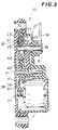
- the automatic door lock/unlock device generally comprises a door lock mechanism 1 in a per se well known construction, a manually operable door lock knob 3 connected to an actuation rod 2 of the door lock mechanism 2 via a stem 4, an electrically driven actuator 20 having a driving shaft 35 and rotatable arm 36 secured to the driving shaft at one end thereof for rotation therewith.
- the rotatable arm 36 is connected to the actuation rod 2 of the door lock mechanism 1 via a link 30 in order to operate the door lock mechanism between a door lock position and unlock position.
- the position of the actuation rod 2 of the door lock mechanism 1 is illustrated as unlocked position in the solid line and the locked position in the phantom line.
- the stroke of the actuation rod 2 for changing the door lock mechanism position between the lock position and unlock position is 1 1
- the rotational stroke 1 1 , + 21 5 of the rotatable arm 36 is provided, as shown in Fig. 1, in order to effect the door lock or unlock operation by the movement of the rotatable arm 36.
- the actuator 20 has electric terminals 5 and 6 extending from an actuator housing 27 and respectively connected to a vehicle battery 9 via a door lock switch 45 and a door unlock switch 46.
- the rotatable arm 36 with the driving shaft 35 is thus rotated in both locking and unlocking directions depending on the switch positions of the door lock switch 45 and the door unlock switch 46.
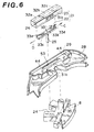
- the driving shaft 35 is connected to a drive pinion 37 of an electrically driven reversible motor 7 via a reduction gear assembly 40 and a rack member 8.
- the reduction gear assembly 38 includes an idler gear 40 and an idler pinion 39 rotatably mounted on a common axle 51.
- the idler gear 40 has a larger diameter than the idler pinion 39 and is associated with the latter with an interengagement mechanism 50.
- the interengagement mechanism 50 comprises a spring 41 inserted in a recess formed on one surface of the idler gear 40.
- the spring 41 has generally circular configuration and having ends 52 and 53 extending from the major section of the spring 41. The ends 52 and 53 are normally urged in a direction away from each other.
- the idler gear 40 has a projection 43 protruding into the recess.
- the projection 43 is located in the recess so that it may abut against one the ends 52 and 53 of the spring 41.
- the idler pinion 39 is formed with a projection 42 projecting toward the recess of the idler gear 40.
- the projection 42 is adapted to abut against one of the ends 52 and 53 while the idler pinion is rotated.
- This interengagement mechanism construction permits the idler pinion 39 to rotate independently of the idler gear 40. As the idler pinion 39 is operated to rotate by the door lock knob 3 via the rack member 8, the door lock knob 3 can be manually operated independently of the motor 7 to reduce required manual operation force.
- a stop switch 21 is provided for detecting the end of the rotational movement of the rack member 8 and for stopping the drive of the motor 7.
- the stop switch 21 generally comprises a movable contactor holder 22 with a pin 25 protruding therefrom and engageable with a cut-out 24 formed in the rack member 8 and a terminal block 23 which is received in a recess 62 and 29 respectively formed in the housing 27 and a switch casing 28.
- the switch casing 28 is formed with a pair of projections 44 to resiliently hold the terminal block 23 in the recess 29.
- the movable contactor holder 22 is attached with a contactor 33.
- the contactor 33 has four terminals 33a, 33b, 33c and 33d respectively bent away from the contactor holder 22.
- the pin 25 of the contactor holder 22 extends through an elongated opening 63 formed in the switch casing 28 so that the contactor holder 22 can move along the elongated opening 63.
- Stationary terminals 32a, 32b and 32c are secured on the inner surface of the terminal block 23.
- the contactor holder 22 with the contactor 33 is received in a recess 26 of the terminal block 23 to mate the terminals 33a, 33b, 33c and 33d thereof to the stationary terminals 32a, 32b and 32c.
- the terminals 33a, 33b, 33c and 33d of the contactor 33 and the stationary terminals 32a, 32b and 32c are so related that the contactor 33 always bridges two of the three stationary terminals by contacting at least two of the four terminals to each of two stationary terminals.
- the terminal block 23 is movable with respect to the recess 29 of the switch casing.
- the terminal block 23 is formed with teeth 31a on the outer periphery thereof.
- the switch casing 28 is formed with a teeth 31 b engageable with the teeth 31a a of the terminal block 23.
- the teeth 31 a and 31 b constitute a positioning means for positioning the terminal block 23 in the recess 29.
- Figs. 7 to 9 illustrate a driving circuit of the motor 7 in locking and unlocking positions.
- the stationary terminal 32a is connected to the vehicle battery 9 via the door unlock switch 46.
- the stationary terminal 32c is connected to the vehicle battery 9 via the motor 7 and the door lock switch 45.
- the stationary terminal 32b is connected to the stationary terminals 32a, 32c via lines 34c and 34d with diodes 34a and 34b.
- the diodes 34a and 34b serve as safety means for preventing the motor 7 from being driven in the door locking direction while the door lock mechanism is in locking position or in door unlocking direction while the door locking mechanism is in unlocking position.
- the door lock switch 45 has a switching member 45a and terminals 45b and 45c.
- the terminal 45b is connected to the positive terminal 9a of the vehicle battery via a line 45d and the terminal 45c is connected to the negative terminal 9b of the vehicle battery 9 via a line 45e.
- the door unlock switch 46 has a switching terminal 46a and terminals 46b and 46c.
- the terminal 46b is connected to the positive terminal 9a of the vehicle battery 9 via lines 46d and 45d
- the terminal 46c is connected to the negative terminal of the vehicle battery 9 via lines 46e and 45e.
- the switching members 45a and 46a are normally urged to the terminals 45c and 46c to be connected to the negative terminal 9b of the vehicle battery.
- the door lock mechanism 1 In the position of the actuator20 of Fig. 2, the door lock mechanism 1 is in the unlocking position. At this position, if the door lock switch 45 is turned to contact the switching member 45a to the terminal 45b, as shown in Fig. 8.
- the driving circuit for the reversible motor 7 is completed to drive the motor in the counterclockwise direction in relation to Fig. 2.
- the drive pinion 37 is thus rotate counterclockwise to drive the idler gear 40 clockwise.
- the idler pinion 39 is rotated clockwise together with the idler gear 40 via the spring 41 to drive the rack member 8 counter-clockwise.
- the driving shaft 35 to which the rack member is fixedly secured is rotate together the rotatable arm 36 into the position shown in Fig. 10.
- the actuation arm 2 of the door lock mechanism 1 is pulled downwardly to place the door lock mechanism at the locking position.
- the movable contactor holder 22 connected to the rack member 8 with the pin and cut-out engagement is moved along the recess 26 of the terminal block.
- the contactor holder22 Assuming the contactor holder22 is positioned at a position of Fig. 6 to connect the stationary terminals 32a and 32b while the door lock mechanism 1 is maintained at the unlocking position of Fig. 2, the movable contactor holder 22 moves to right to establish electrical communication between the stationary terminals 32b and 32c with the contactor 33 as shown in Fig. 9.
- the contactor 33 is placed in a position as shown in Fig. 8. In the position of Fig. 8, the contactor 33 connects the stationary terminal 32a to the stationary terminal 32c to keep power supply to the motor.
- the diode 34a blocks electric current flow therethrough to stop driving of the motor 7.
- the door lock switch 45 is disabled to operate the actuator, further.
- the movable contact holder 22 is moved by an amount 1 2 of Fig. 5 to move the contact 33 from the position of Fig. 7 to the position of Fig. 9.
- the contactor holder 22 is placed at a position to leave a clearance 1 4 between it and the adjacent periphery of the terminal block 23.
- the door lock mechanism 1 In a switch position as illustrated with the phantom line in Fig. 1, the door lock mechanism 1 is in the locked position. At this position, even if the door lock switch 45 is turned to contact the switching member 45a to the terminal 45b, as shown in Fig. 9, since the movable contactor 33 is positioned at the position as shown in Fig. 9, the driving circuit for the reversible motor 7 does not supply power to the motor to drive same in the locking or clockwise direction of Fig. 2. At this position, the power is supplied to the reversible motor 7 in response to turning on of the door unlocking switch 46 to connect the swtich member46a to the terminal 46b. The drive pinion 37 is thus rotate counterclockwise to drive the idler gear 40 clockwise.
- the idler pinion 39 is rotated clockwise together with the idler gear 40 via the spring 41 to drive the rack member 8 counterclockwise.
- the driving shaft 35 to which the rack member is fixedly secured is rotated together the rotatable arm 36.
- the actuation arm 2 of the door lock mechanism 1 is pushed up-wardly to place the door lock mechanism at the unlocking position, as shown in Fig. 2.
- the contactor 33 is placed at the position of Fig. 7.
- the terminal block 23 is positioned to place the stationary terminals 32a, 32b and 32c at an appropriate location with respect to the contactor 33 according to the door lock mechanism position.
- the terminal block 23 is so related to the switch casing 28 as to have a clearance 1 3 between the opposing periphery of the terminal block and the recess 29, the adjustment of the relationship in position of the contactor 33 and the stationary terminals 32a, 32b and 32c can be done by moving the terminal block.
- the teeth 31a a and 31 b of the terminal block 23 and the. switch casing 28 serves to fix the terminal block at the adjusted position.
Landscapes
- Lock And Its Accessories (AREA)
Applications Claiming Priority (2)
| Application Number | Priority Date | Filing Date | Title |
|---|---|---|---|
| JP56529/81 | 1981-04-15 | ||
| JP5652981A JPS57172083A (en) | 1981-04-15 | 1981-04-15 | Door lock manipulating apparatus |
Publications (4)
| Publication Number | Publication Date |
|---|---|
| EP0064602A2 EP0064602A2 (en) | 1982-11-17 |
| EP0064602A3 EP0064602A3 (en) | 1983-04-27 |
| EP0064602B1 EP0064602B1 (en) | 1987-01-21 |
| EP0064602B2 true EP0064602B2 (en) | 1992-05-06 |
Family
ID=13029623
Family Applications (1)
| Application Number | Title | Priority Date | Filing Date |
|---|---|---|---|
| EP19820102910 Expired - Lifetime EP0064602B2 (en) | 1981-04-15 | 1982-04-05 | Automatic door locking/unlocking device for an automotive vehicle |
Country Status (4)
| Country | Link |
|---|---|
| US (1) | US4502718A (enExample) |
| EP (1) | EP0064602B2 (enExample) |
| JP (1) | JPS57172083A (enExample) |
| DE (1) | DE3275211D1 (enExample) |
Families Citing this family (44)
| Publication number | Priority date | Publication date | Assignee | Title |
|---|---|---|---|---|
| JPS6022656U (ja) * | 1983-07-21 | 1985-02-16 | 株式会社 大井製作所 | 自動車用ドアロツク操作装置 |
| JPS6051266U (ja) * | 1983-09-16 | 1985-04-10 | 株式会社 三ツ葉電機製作所 | ドアロツクアクチユエ−タ |
| JPS60113856A (ja) * | 1983-11-26 | 1985-06-20 | Nippon Denso Co Ltd | 動力伝達装置 |
| US4672375A (en) * | 1983-11-29 | 1987-06-09 | Nissan Motor Company, Limited | Keyless entry system for automotive devices with compact, portable wireless code transmitter, and feature for preventing users from locking transmitter in vehicle |
| GB2159001B (en) * | 1984-05-19 | 1987-11-11 | Delco Prod Overseas | Electrically-operable actuator |
| US4616527A (en) * | 1985-01-14 | 1986-10-14 | General Motors Corporation | Remote actuator |
| FR2580716B1 (fr) * | 1985-04-18 | 1987-05-29 | Signal Vision Sa | Actionneur electro-mecanique a commande par moteur electrique par demi-tour |
| JPS62101782A (ja) * | 1985-10-30 | 1987-05-12 | 株式会社 大井製作所 | 自動車用ドアロツク制御装置 |
| US4904006A (en) * | 1986-10-06 | 1990-02-27 | Aisin Seiki Kabushiki Kaisha | Door lock assembly for automotive vehicles |
| JPH0625507B2 (ja) * | 1986-12-09 | 1994-04-06 | 株式会社三ツ葉電機製作所 | 車両における自動ドアロツク制御装置 |
| KR930000850B1 (ko) * | 1986-12-26 | 1993-02-06 | 가부시끼가이샤 안세이고오교오 | 자동차용 도어 로크장치 |
| DE3703392A1 (de) * | 1987-02-05 | 1988-08-18 | Fichtel & Sachs Ag | Elektrische zentral-verriegelungs-einrichtung fuer tueren, hauben und/oder deckel insbesondere an kraftfahrzeugen |
| JPH0735708B2 (ja) * | 1987-11-30 | 1995-04-19 | 株式会社大井製作所 | 自動車用ドアロック装置 |
| JPH0194563U (enExample) * | 1987-12-16 | 1989-06-22 | ||
| US5169186A (en) * | 1988-07-21 | 1992-12-08 | Aisin Seiki Kabushiki Kaisha | Door lock device |
| US5125702A (en) * | 1988-07-21 | 1992-06-30 | Aisin Seiki Kabushiki Kaisha | Door lock device |
| DE3933467C2 (de) * | 1988-07-21 | 1995-12-07 | Aisin Seiki | Türverriegelungsvorrichtung |
| JPH0723658B2 (ja) * | 1988-12-21 | 1995-03-15 | 三井金属鉱業株式会社 | 車両用ロック機構 |
| DE3934982A1 (de) * | 1989-10-20 | 1990-05-10 | Bocklenberg & Motte Bomoro | Kraftfahrzeug-tuerschloss |
| JP2556789B2 (ja) * | 1991-03-29 | 1996-11-20 | 株式会社大井製作所 | 自動車用ドアロックの施解錠操作装置 |
| IT1250204B (it) * | 1991-07-23 | 1995-04-03 | Roltra Morse Spa | Dispositivo attuatore, particolarmente per l'azionamento di una leva di sicurezza di una serratura per portiere di veicoli |
| DE4129705A1 (de) * | 1991-09-06 | 1993-03-11 | Swf Auto Electric Gmbh | Zentralverriegelungsanlage fuer kraftfahrzeuge |
| JP2559087Y2 (ja) * | 1992-03-17 | 1998-01-14 | 自動車電機工業株式会社 | ドアロックアクチュエータ |
| JPH0575374U (ja) * | 1992-03-17 | 1993-10-15 | 自動車電機工業株式会社 | アクチュエータ |
| GB2267928B (en) * | 1992-06-16 | 1995-04-26 | Rockwell Automotive Body Co | Vehicle locking systems |
| DE4226512C2 (de) * | 1992-08-11 | 2001-11-22 | Valeo Auto Electric Gmbh | Schaltschieber |
| JP2847461B2 (ja) * | 1993-07-05 | 1999-01-20 | 三井金属鉱業株式会社 | ドアロック装置におけるスイッチ機構 |
| DE69424654T2 (de) * | 1993-12-10 | 2001-01-25 | Denso Corp., Kariya | Türschliessantrieb |
| JPH0828119A (ja) * | 1994-05-13 | 1996-01-30 | Nippondenso Co Ltd | ドアロック駆動装置 |
| WO1997003268A1 (en) * | 1995-07-11 | 1997-01-30 | Stoneridge, Inc. | Adjunct actuator for vehicle door lock |
| US5835022A (en) * | 1995-08-02 | 1998-11-10 | Nissan Motor Co., Ltd. | Keyless entry system |
| GB2322409B (en) * | 1996-12-16 | 2001-05-23 | John Phillip Chevalier | Control system for opening a door |
| EP1518982B1 (en) * | 1997-12-12 | 2009-07-29 | John Phillip Chevalier | Latch arrangements for automotive doors or other closures |
| US6386599B1 (en) | 1999-08-12 | 2002-05-14 | John Phillip Chevalier | Latch arrangement for automotive door |
| AU9188198A (en) * | 1998-09-29 | 2000-04-17 | Mitsubishi Denki Kabushiki Kaisha | Motor supporting device |
| DE19958288A1 (de) * | 1999-12-03 | 2001-06-13 | Bosch Gmbh Robert | Elektromotorischer Stellantrieb für ein Kraftfahrzeugschloss |
| US7472628B2 (en) * | 2003-01-15 | 2009-01-06 | Intier Automotive Closures Inc. | Door handle input decoupler for a cinching latch actuator |
| US20040159518A1 (en) * | 2003-01-15 | 2004-08-19 | Oberheide G. Clarke | Door handle input decoupler for a cinching latch actuator |
| FR2859234B1 (fr) * | 2003-08-28 | 2006-01-13 | Valeo Securite Habitacle | Systeme de detection d'etats d'une serrure de vehicule automobile |
| DE102004049401A1 (de) * | 2004-10-08 | 2006-04-13 | Kiekert Ag | Kraftfahrzeugtürverschluss |
| KR101108135B1 (ko) * | 2005-04-04 | 2012-01-31 | 한옥순 | 도어록 장치 |
| GB0518133D0 (en) * | 2005-09-06 | 2005-10-12 | Haldex Brake Products Ltd | Braking system |
| US20080012354A1 (en) * | 2006-05-26 | 2008-01-17 | John Phillip Chevalier | Latch control by gear position sensing |
| EP2195500B1 (en) * | 2007-10-10 | 2017-05-03 | Magna Closures Inc. | Door latch with fast unlock |
Family Cites Families (16)
| Publication number | Priority date | Publication date | Assignee | Title |
|---|---|---|---|---|
| US3483955A (en) * | 1968-01-18 | 1969-12-16 | Dodwell John M | Clutch band and method of making same |
| US3703646A (en) * | 1970-12-11 | 1972-11-21 | Murphy Ind Inc G W | Electric tool with trigger switch and lock-out arrangement |
| US3702551A (en) * | 1971-02-19 | 1972-11-14 | Mosler Safe Co | Time delay combination locks |
| US3947391A (en) * | 1974-09-20 | 1976-03-30 | Switchcraft, Inc. | Electrical slide switch |
| US3947060A (en) * | 1975-02-26 | 1976-03-30 | Pulse Dynamics Manufacturing Corporation | Bolt mechanism with manual override |
| DE2547291A1 (de) * | 1975-10-22 | 1977-04-28 | Maerklin & Cie Gmbh Geb | Vorrichtung zum begrenzen des bewegungsweges eines stellgliedes der haus- und fahrzeug- einrichtungstechnik |
| IT1091053B (it) * | 1975-12-01 | 1985-06-26 | Kiekert Soehne Arn | Dispositivo di bloccaggio centrale per porte di veicoli |
| JPS5430316Y2 (enExample) * | 1976-01-13 | 1979-09-25 | ||
| JPS5430317Y2 (enExample) * | 1976-04-07 | 1979-09-25 | ||
| DE2721970A1 (de) * | 1977-05-14 | 1978-11-16 | Fichtel & Sachs Ag | Schliess- und/oder verriegelungseinrichtung fuer fahrzeugtueren |
| US4126341A (en) * | 1977-08-12 | 1978-11-21 | Adams Rite Manufacturing Co. | Motor driven lock actuator |
| DE2801284C2 (de) * | 1978-01-13 | 1987-04-30 | Helmut Dipl.-Ing. 7140 Ludwigsburg Espenschied | Endschalter |
| DE2825355C2 (de) * | 1978-06-09 | 1984-02-09 | Vdo Adolf Schindling Ag, 6000 Frankfurt | Elektrische Zentralverriegelung für Kraftfahrzeugtürverschlüsse |
| US4270783A (en) * | 1979-01-24 | 1981-06-02 | Lake Center Industries | Door lock actuator |
| DE2923447A1 (de) * | 1979-06-09 | 1980-12-11 | Fichtel & Sachs Ag | Antrieb fuer eine schliess- und/oder verriegelungseinrichtung an einer fahrzeugtuere |
| DE2948390A1 (de) * | 1979-12-01 | 1981-06-04 | Sachs Systemtechnik Gmbh, 8720 Schweinfurt | Zentralverriegelungsanlage |
-
1981
- 1981-04-15 JP JP5652981A patent/JPS57172083A/ja active Granted
-
1982
- 1982-04-01 US US06/364,234 patent/US4502718A/en not_active Expired - Lifetime
- 1982-04-05 EP EP19820102910 patent/EP0064602B2/en not_active Expired - Lifetime
- 1982-04-05 DE DE8282102910T patent/DE3275211D1/de not_active Expired
Also Published As
| Publication number | Publication date |
|---|---|
| EP0064602A3 (en) | 1983-04-27 |
| EP0064602B1 (en) | 1987-01-21 |
| EP0064602A2 (en) | 1982-11-17 |
| JPS57172083A (en) | 1982-10-22 |
| JPS6226383B2 (enExample) | 1987-06-09 |
| US4502718A (en) | 1985-03-05 |
| DE3275211D1 (en) | 1987-02-26 |
Similar Documents
| Publication | Publication Date | Title |
|---|---|---|
| EP0064602B2 (en) | Automatic door locking/unlocking device for an automotive vehicle | |
| US5673578A (en) | Motor vehicle door lock with central locking system drive | |
| US4657362A (en) | Door mirror | |
| US5323131A (en) | Molded case circuit breaker motor operator | |
| US5535607A (en) | Door latch with integral switch | |
| EP0085296B1 (en) | Closure lock system | |
| US5510583A (en) | Assembly for sequential switching | |
| US4872714A (en) | Electrically-powered vehicle lock | |
| US4632525A (en) | Side-mirror driving apparatus | |
| JPH0512977A (ja) | 可変手動制御遮断器 | |
| JPH0658026B2 (ja) | 自動車ドアロツク用調節装置 | |
| EP0572970B1 (en) | Electric operating device for circuit breaker | |
| US6109079A (en) | Vehicle door latch device and method of controlling thereof | |
| US3974348A (en) | Reversing switch controlled by a safety lock having a cylindrical barrel | |
| US6203469B1 (en) | Operating apparatus for use in connection with a dual-mode transmission | |
| EP1296343B1 (en) | Switch, in particular battery cutout switch for vehicles and the like | |
| US4698560A (en) | Adjusting device, especially for locking and unlocking motor vehicle doors | |
| GB2301617A (en) | Vehicle door latch device and method of controlling same | |
| JPH0214612Y2 (enExample) | ||
| US3901347A (en) | Vehicle control system | |
| JP2575377Y2 (ja) | 回路遮断器の操作装置 | |
| JPH065481Y2 (ja) | 電気錠 | |
| JP3113142B2 (ja) | 回路遮断ユニット | |
| JPH026587Y2 (enExample) | ||
| US4431883A (en) | Dual action switch assembly |
Legal Events
| Date | Code | Title | Description |
|---|---|---|---|
| PUAI | Public reference made under article 153(3) epc to a published international application that has entered the european phase |
Free format text: ORIGINAL CODE: 0009012 |
|
| 17P | Request for examination filed |
Effective date: 19820405 |
|
| AK | Designated contracting states |
Designated state(s): DE FR GB |
|
| PUAL | Search report despatched |
Free format text: ORIGINAL CODE: 0009013 |
|
| AK | Designated contracting states |
Designated state(s): DE FR GB |
|
| RAP1 | Party data changed (applicant data changed or rights of an application transferred) |
Owner name: JIDOSHA DENKI KOGYO KABUSHIKI KAISHA Owner name: NISSAN MOTOR CO., LTD. |
|
| GRAA | (expected) grant |
Free format text: ORIGINAL CODE: 0009210 |
|
| AK | Designated contracting states |
Kind code of ref document: B1 Designated state(s): DE FR GB |
|
| REF | Corresponds to: |
Ref document number: 3275211 Country of ref document: DE Date of ref document: 19870226 |
|
| ET | Fr: translation filed | ||
| PLBI | Opposition filed |
Free format text: ORIGINAL CODE: 0009260 |
|
| 26 | Opposition filed |
Opponent name: SWF AUTO-ELECTRIC GMBH Effective date: 19871019 |
|
| PUAH | Patent maintained in amended form |
Free format text: ORIGINAL CODE: 0009272 |
|
| STAA | Information on the status of an ep patent application or granted ep patent |
Free format text: STATUS: PATENT MAINTAINED AS AMENDED |
|
| 27A | Patent maintained in amended form |
Effective date: 19920506 |
|
| AK | Designated contracting states |
Kind code of ref document: B2 Designated state(s): DE FR GB |
|
| ET3 | Fr: translation filed ** decision concerning opposition | ||
| PGFP | Annual fee paid to national office [announced via postgrant information from national office to epo] |
Ref country code: DE Payment date: 20010326 Year of fee payment: 20 |
|
| PGFP | Annual fee paid to national office [announced via postgrant information from national office to epo] |
Ref country code: GB Payment date: 20010404 Year of fee payment: 20 |
|
| PGFP | Annual fee paid to national office [announced via postgrant information from national office to epo] |
Ref country code: FR Payment date: 20010409 Year of fee payment: 20 |
|
| REG | Reference to a national code |
Ref country code: GB Ref legal event code: IF02 |
|
| PG25 | Lapsed in a contracting state [announced via postgrant information from national office to epo] |
Ref country code: GB Free format text: LAPSE BECAUSE OF EXPIRATION OF PROTECTION Effective date: 20020404 |