EP0063969A1 - Siège comportant un accoudoir pouvant occuper deux positions - Google Patents
Siège comportant un accoudoir pouvant occuper deux positions Download PDFInfo
- Publication number
- EP0063969A1 EP0063969A1 EP82400536A EP82400536A EP0063969A1 EP 0063969 A1 EP0063969 A1 EP 0063969A1 EP 82400536 A EP82400536 A EP 82400536A EP 82400536 A EP82400536 A EP 82400536A EP 0063969 A1 EP0063969 A1 EP 0063969A1
- Authority
- EP
- European Patent Office
- Prior art keywords
- seat
- arm rest
- pin
- cut
- stopper
- Prior art date
- Legal status (The legal status is an assumption and is not a legal conclusion. Google has not performed a legal analysis and makes no representation as to the accuracy of the status listed.)
- Granted
Links
Images


Classifications
-
- B—PERFORMING OPERATIONS; TRANSPORTING
- B60—VEHICLES IN GENERAL
- B60N—SEATS SPECIALLY ADAPTED FOR VEHICLES; VEHICLE PASSENGER ACCOMMODATION NOT OTHERWISE PROVIDED FOR
- B60N2/00—Seats specially adapted for vehicles; Arrangement or mounting of seats in vehicles
- B60N2/75—Arm-rests
- B60N2/763—Arm-rests adjustable
- B60N2/77—Height adjustment
-
- B—PERFORMING OPERATIONS; TRANSPORTING
- B60—VEHICLES IN GENERAL
- B60N—SEATS SPECIALLY ADAPTED FOR VEHICLES; VEHICLE PASSENGER ACCOMMODATION NOT OTHERWISE PROVIDED FOR
- B60N2/00—Seats specially adapted for vehicles; Arrangement or mounting of seats in vehicles
- B60N2/75—Arm-rests
- B60N2/753—Arm-rests movable to an inoperative position
- B60N2/757—Arm-rests movable to an inoperative position in a recess of the back-rest
-
- B—PERFORMING OPERATIONS; TRANSPORTING
- B60—VEHICLES IN GENERAL
- B60N—SEATS SPECIALLY ADAPTED FOR VEHICLES; VEHICLE PASSENGER ACCOMMODATION NOT OTHERWISE PROVIDED FOR
- B60N2/00—Seats specially adapted for vehicles; Arrangement or mounting of seats in vehicles
- B60N2/75—Arm-rests
- B60N2/763—Arm-rests adjustable
- B60N2/767—Angle adjustment
Definitions
- the present invention relates generally to a seat with an arm rest adjustable to either of two angular positions and at least two heights with respect to the seat back, as a piece of furniture or as a passenger's seat mounted in an automotive vehicle, vessel and air plane, etc.
- a conventional seat comprises a seat, a seat back and an arm rest supported by the seat back via a linkage so as to be free to tilt forward at an angle with respect to the seat back.
- the center portion of the seat back is provided with a recess in which the arm rest can be housed.
- the linkage between the seat back and arm rest comprises a first bracket attached to a frame provided at the recess in the seat back, a second bracket attached to a frame along the longitudinal axis of the arm rest, and upper and lower link brackets between the first and second brackets.
- each of the upper and lower link brackets is merely rotatably fixed to the first bracket so that the height of the arm rest with respect to the seat when the arm rest is tilted forward so as to be approximately parallel to the seat is fixed. Consequently, free adjustment of the height for the arm rest is impossible.
- other kinds of seats may employ a bracket of a pin hinge type in the seat back in place of the bracket of the link type.
- the conventional seat described above has the same drawback as the conventional seat of the link type.
- a seat having an arm rest and a seat back comprising :
- this can be achieved by supporting an axle supporting member for rotatably supporting the arm rest at one end of the first bracket attached to the seat back, providing a cut-out engagable slidably with a stopper pin within a second bracket for fixing the seat back or other seat member so that a movement amount of the stopper pin is restricted during a normal rotation of the stopper pin provided at the arm rest, providing a pin receiving member at an upper portion of the cut-out for receiving the stopper pin when the arm rest is moved upward, and furthermore providing a first rotating center of the arm rest at both first and second brackets and a second rotating center for adjusting the height of the arm rest in horizontal direction with respect to the seat.
- numeral 1 denotes a seat back
- numeral 2 denotes an arm rest attached to the seat back 1 between two body-sized portions of the seat
- numeral 3 denotes a linkage for supporting the arm rest 2 in a position approximately parallel with respect to the seat 1'
- numeral 4 denotes a recess in the seat back 1 for housing the arm rest 2 therewithin.
- the linkage 3 comprises, as shown in Figure 2, (a) a first fixing bracket 1a attached to the seat back 1, (b) a second fixing bracket 2a attached to the frame of the arm rest 2, and (c) upper and lower link brackets 3a and 3b for linking the second bracket with the first bracket.
- Such a linkage 3 as shown in Figure 2 does not permit adjustment of the height of the arm rest 2 with respect to the seat 1' when the arm rest 2 is tilted toward the seat 1' as shown in Figure 2.
- FIGS 3 through 7 illustrate a preferred embodiment of the seat according to the present invention.
- the seat according to the present invention comprises essentially a first bracket 5 acting as a rotational member and a second bracket 6 acting as a fixing member, in addition to the conventional elements, i.e., the seat 1', seat back 1 and arm rest 2.
- the first bracket 5 comprises a first hole 9 for a bolt 8 near one end thereof and a second hole for a pin 14 near the other end thereof, as can be clearly seen in Figure 7.
- the bolt 8 is used specifically as "an axle supporting member" which rotatably supports a side surface 2c of the arm rest 2.
- the first bracket 5 is linked with the arm rest 2 by screwing the bolt 8 into the first hole 9 and into a third hole 11 of a nut 10 welded"to the side surface 2c of the arm rest 2 (in more detail, provided on an arm rest frame 2d within the side surface 2c of the arm rest 2 as clearly seen from Figure 8).
- the bolt 8 serves as a first rotating center 12 for the arm rest 2.
- the second hole provided at the end of the first bracket 5 is linked with a tab 13 of the second bracket 6 to be described hereinafter via a hinge pin 14.
- the hinge pin 14 serves as a second rotating center 15 for adjusting the height of the arm rest 2.
- the second bracket 6 is fixed to the seat back 1 to support the first bracket 5 via the hinge pin 14 as stated above.
- the second bracket 6 is provided with at least one fourth hole 19 for at least one screw 18.
- the screw 18 is inserted through the fourth hole 19 and screwed into another nut 17 on the opposite side of the seat back side surface 1a which faces the side surface 2c of the arm rest 2 when the arm rest 2 is housed within the recess 4 of the seat back 1.
- the second bracket 6 is provided with an arc-shaped cut-out 21 for receiving a stopper pin 20 projecting from the side surface 2c of the arm rest 2 and limiting the range of movement of the stopper pin 20 during normal rotation of the arm rest 2.
- the second bracket 6 is provided with a groove 22 near the upper end of the cut-out 21 which allows engagement and disengagement of the stopper pin 20 from the cut-out 21 and also a pin-receiving member 23 at the upper portion of the bracket 6 for receiving the stopper pin 20 when disengaged from the cut-out 21.
- the pin receiving member 23 is of a substantially semi-circular shape and is formed integrally with the second bracket 6.
- a pin-receiving member 23 of another material may be attached to the second bracket 6 by means of welding or another technique.
- the tab 13 is provided opposite the cut-out 21 for linking the second bracket 6 with the first bracket via the hinge pin 14.
- first and second brackets 5 and 6 are provided in combination at both sides of the arm rest 2 and corresponding sides of the recess 4 of the seat back 1.
- the second bracket 6 may be attached to the vehicle body at the rear surface of the seat back 1 or another fixing position (not shown).
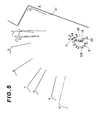
- the first rotating center 12 is placed at the lowest position thereof and the arm rest 2 can be rotated counterclockwise and clockwise within a range shown by an arrow-marked line A about the first rotating center 12.
- the arm rest 2 is pulled forward with respect to the seat back 1 (left direction in Figure 4) from a position 2' denoted by a phantom line
- the arm rest 2 is rotated counterclockwise to tilt forward with respect to the seat back 1 about the first rotating center and the stopper pin 20 is engaged with the arc-shaped cut- out 21 of the second bracket 6 so that the range of movement of the stopper pin 20 is limited to between a position 20A denoted by a phantom line in Figure 4 and another position 20B denoted by a dotted line.
- the arm rest 2 is simultaneously rotated and translated from the first position (1) to ninth position (9) shown in Figure 5.
- the distance of height of the stopper pin, i.e. the vertical movement of the arm rest 2 is denoted by B in Figure 6.
- the stopper pin 20 is then supported by the pin receiving member 23 of the second bracket 6.
- the arm rest 2 In order to return the arm rest 2 to its original height within the recess 4 of the seat back 1, the arm rest 2 needs to be lifted slightly upward to disengage the stopper pin 20 from the pin-receiving member 23. Subsequently, when the arm rest 2 is lowered by its own weight with elements 8 and 20 of the first bracket 5 following the loci S.B. and P in the reversed direction as described above, the stopper pin 20 is engaged with the cut-out 21 so that the arm rest 2 returns to its original position.
- the shape of the second bracket 6 is not limited to that shown in these drawings. Particularly, a pin-receiving member may also be formed along the cut-out 21.
- a seat of the construction described above allows the height of an arm rest with respect to the seat to be adjusted to either of two steps according to the convenience of the user. Furthermore, modification of a conventional seat to include the features of the present invention can be made simply by replacing the first and second brackets described above without modifications to the seat back, so that the difference between the two height positions of the arm rest can easily be set according to the model and type of automotive vehicle in which the seat is mounted.
- portion of the second bracket to be attached to the seat back in the preferred embodiment may be attached to another fixed structure adjacent to the seat back.
Landscapes
- Engineering & Computer Science (AREA)
- Aviation & Aerospace Engineering (AREA)
- Transportation (AREA)
- Mechanical Engineering (AREA)
- Seats For Vehicles (AREA)
- Chairs For Special Purposes, Such As Reclining Chairs (AREA)
Applications Claiming Priority (2)
| Application Number | Priority Date | Filing Date | Title |
|---|---|---|---|
| JP56044477A JPS57160414A (en) | 1981-03-26 | 1981-03-26 | Armrest revolving apparatus |
| JP44477/81 | 1981-03-26 |
Publications (2)
| Publication Number | Publication Date |
|---|---|
| EP0063969A1 true EP0063969A1 (fr) | 1982-11-03 |
| EP0063969B1 EP0063969B1 (fr) | 1985-10-30 |
Family
ID=12692606
Family Applications (1)
| Application Number | Title | Priority Date | Filing Date |
|---|---|---|---|
| EP82400536A Expired EP0063969B1 (fr) | 1981-03-26 | 1982-03-24 | Siège comportant un accoudoir pouvant occuper deux positions |
Country Status (4)
| Country | Link |
|---|---|
| US (1) | US4435011A (fr) |
| EP (1) | EP0063969B1 (fr) |
| JP (1) | JPS57160414A (fr) |
| DE (1) | DE3267100D1 (fr) |
Cited By (7)
| Publication number | Priority date | Publication date | Assignee | Title |
|---|---|---|---|---|
| US4577905A (en) * | 1983-07-07 | 1986-03-25 | Grant Robert J | Vehicle armrest |
| EP0245733A2 (fr) * | 1986-05-06 | 1987-11-19 | Adam Opel Aktiengesellschaft | Dispositif pour le logement détachable d'accoudoirs pivotants de sièges notamment d'accoudoirs centraux de sièges arrières de véhicules automobiles |
| EP0296939A1 (fr) * | 1987-06-24 | 1988-12-28 | Automobiles Peugeot | Accoudoir central avant à deux positions stables d'un véhicule automobile |
| US4978171A (en) * | 1989-02-27 | 1990-12-18 | Ikeda Bussan Co., Ltd. | Arm rest device for use with vehicular seat |
| FR2661376A1 (fr) * | 1990-04-28 | 1991-10-31 | Ikeda Bussan Co | Siege pour vehicule automobile. |
| FR2669586A1 (fr) * | 1990-11-26 | 1992-05-29 | Ikeda Bussan Co | Structure de fixation d'un accoudoir escamotable a un dossier de siege. |
| FR2735732A1 (fr) * | 1995-06-26 | 1996-12-27 | Faure Bertrand Equipements Sa | Accoudoir rabattable, et siege de vehicule equipe d'un tel accoudoir |
Families Citing this family (38)
| Publication number | Priority date | Publication date | Assignee | Title |
|---|---|---|---|---|
| GB2127285A (en) * | 1982-09-22 | 1984-04-11 | Ford Motor Co | Armrest lock for a motor car |
| US4655501A (en) * | 1985-07-25 | 1987-04-07 | Nhk Spring Co., Ltd. | Armrest of a seat |
| US4848840A (en) * | 1988-08-11 | 1989-07-18 | Tachi-S Co., Ltd. | Locking mechanism for armrest |
| JPH0252309U (fr) * | 1988-09-30 | 1990-04-16 | ||
| JPH068755Y2 (ja) * | 1989-07-25 | 1994-03-09 | 池田物産株式会社 | シートにおけるアームレスト支持構造 |
| DE4121408A1 (de) * | 1991-06-28 | 1993-01-07 | Nokia Deutschland Gmbh | Wiedergabeanordnung fuer basstoene im kraftfahrzeug |
| US5292171A (en) * | 1992-06-01 | 1994-03-08 | Lear Seating Corporation | Vehicle seat armrest bracket and cover assembly |
| US5630644A (en) * | 1993-08-20 | 1997-05-20 | La-Z-Boy Chair Company | Modular sofa assembly and mounting apparatus for securing independent sections thereof |
| US5489143A (en) * | 1993-09-06 | 1996-02-06 | Suncall Corporation | Arm rest device |
| BR9503277A (pt) * | 1995-07-07 | 1996-03-26 | Alexandre Antonio Fornasari | Banco embutido para bebè para transporte em veiculos |
| US5743593A (en) * | 1996-08-09 | 1998-04-28 | Lear Corporation | Vehicle seat with integral child seat |
| US5752739A (en) * | 1996-09-30 | 1998-05-19 | Tachi-S Co., Ltd. | Mounting for an armrest in seat |
| US5941603A (en) * | 1997-01-16 | 1999-08-24 | Grammer Ag | Vehicle seat armrest |
| JPH1118874A (ja) * | 1997-06-27 | 1999-01-26 | Ikeda Bussan Co Ltd | 車両用アームレスト |
| US5873633A (en) * | 1997-10-08 | 1999-02-23 | Lear Corporation | Retardation lock member for motor vehicle seat component |
| US5984416A (en) * | 1998-04-30 | 1999-11-16 | Calvin College | Adjustable armrest |
| US6132128A (en) * | 1998-06-17 | 2000-10-17 | Prince Corporation | Snap-on control member |
| US6283551B1 (en) * | 1999-07-07 | 2001-09-04 | Media Technology Source, Inc. | Pivoting armrest with cupholder |
| US6471297B1 (en) | 2000-08-25 | 2002-10-29 | Magna Seating Systems, Inc. | Pivotal and retractable armrest assembly |
| CA2441509C (fr) * | 2002-09-20 | 2006-12-12 | Faurecia Automotive Seating Canada Limited | Mecanisme de reglage d'accoudoir et methode d'installation |
| DE10340797B4 (de) * | 2003-09-02 | 2009-08-20 | Johnson Controls Gmbh | Armlehne, insbesondere für ein Kraftfahrzeug |
| US7077477B1 (en) * | 2004-12-22 | 2006-07-18 | Daimlerchrysler Corporation | Translating armrest |
| US7857393B2 (en) * | 2007-07-03 | 2010-12-28 | E & E Manufacturing Company Inc. | Adjustable armrest for a road vehicle |
| US7735913B2 (en) * | 2007-12-21 | 2010-06-15 | Ford Global Technologies, Llc | Cover for vehicle seat handle |
| US20090167070A1 (en) * | 2007-12-28 | 2009-07-02 | Toyota Motor Engineering & Manufacturing North America, Inc. | Armrest For Motor Vehicle Seat Assembly |
| FR2942180B1 (fr) * | 2009-02-19 | 2013-02-15 | Faurecia Sieges Automobile | Support d'accoudoir pour siege de vehicule automobile |
| DE102010049497B4 (de) * | 2010-10-27 | 2014-07-03 | F.S. Fehrer Automotive Gmbh | Lagerung einer schwenkbaren Mittelarmlehne |
| DE102011018227B4 (de) * | 2011-04-19 | 2013-08-14 | F.S. Fehrer Automotive Gmbh | Armlehne mit Kunststofflagerung |
| EP2841300B1 (fr) * | 2012-04-24 | 2021-02-17 | Safran Seats USA LLC | Ensemble butée d'accoudoir |
| US9260042B2 (en) * | 2013-06-17 | 2016-02-16 | Zodiac Seat Shells U.S. Llc | Foldable armrest |
| JP6450934B2 (ja) * | 2015-05-08 | 2019-01-16 | トヨタ紡織株式会社 | 乗物用シート |
| US10259368B2 (en) * | 2015-07-24 | 2019-04-16 | Textron Innovations Inc. | Articulating armrest |
| US10112510B2 (en) * | 2015-10-13 | 2018-10-30 | Windsor Machine and Stamping (2009) Ltd. | Lockable armrest |
| KR101905486B1 (ko) * | 2016-10-10 | 2018-10-10 | 주식회사 서연이화 | 차량용 콘솔 암레스트의 힌지 유닛 |
| US10882427B2 (en) * | 2017-09-27 | 2021-01-05 | Gulfstream Aerospace Corporation | Seat assembly including an armrest sub-assembly and method for fabricating the same |
| US10343570B1 (en) * | 2017-12-15 | 2019-07-09 | Lear Corporation | Vehicle armrest mounting assembly and installation method |
| CN109130990B (zh) * | 2018-09-11 | 2021-03-23 | 重庆工业职业技术学院 | 一种多功能汽车扶手箱 |
| DE102021130222A1 (de) | 2021-11-18 | 2023-05-25 | Ford Global Technologies Llc | Halterung zur Anbringung einer schwenkbaren Armlehne an einem Fahrzeugsitz |
Citations (1)
| Publication number | Priority date | Publication date | Assignee | Title |
|---|---|---|---|---|
| FR2287193A1 (fr) * | 1974-10-12 | 1976-05-07 | Daimler Benz Ag | Accoudoir pivotant pour siege de vehicule |
-
1981
- 1981-03-26 JP JP56044477A patent/JPS57160414A/ja active Granted
-
1982
- 1982-03-22 US US06/360,168 patent/US4435011A/en not_active Expired - Lifetime
- 1982-03-24 EP EP82400536A patent/EP0063969B1/fr not_active Expired
- 1982-03-24 DE DE8282400536T patent/DE3267100D1/de not_active Expired
Patent Citations (1)
| Publication number | Priority date | Publication date | Assignee | Title |
|---|---|---|---|---|
| FR2287193A1 (fr) * | 1974-10-12 | 1976-05-07 | Daimler Benz Ag | Accoudoir pivotant pour siege de vehicule |
Cited By (10)
| Publication number | Priority date | Publication date | Assignee | Title |
|---|---|---|---|---|
| US4577905A (en) * | 1983-07-07 | 1986-03-25 | Grant Robert J | Vehicle armrest |
| EP0245733A2 (fr) * | 1986-05-06 | 1987-11-19 | Adam Opel Aktiengesellschaft | Dispositif pour le logement détachable d'accoudoirs pivotants de sièges notamment d'accoudoirs centraux de sièges arrières de véhicules automobiles |
| EP0245733A3 (en) * | 1986-05-06 | 1989-11-29 | Adam Opel Aktiengesellschaft | Device for the detachable method of bearing of hinged armrests of seats especially center armrests of automotive back seats |
| EP0296939A1 (fr) * | 1987-06-24 | 1988-12-28 | Automobiles Peugeot | Accoudoir central avant à deux positions stables d'un véhicule automobile |
| FR2617101A1 (fr) * | 1987-06-24 | 1988-12-30 | Peugeot | Accoudoir central avant a deux positions stables d'un vehicule automobile |
| US4978171A (en) * | 1989-02-27 | 1990-12-18 | Ikeda Bussan Co., Ltd. | Arm rest device for use with vehicular seat |
| FR2661376A1 (fr) * | 1990-04-28 | 1991-10-31 | Ikeda Bussan Co | Siege pour vehicule automobile. |
| FR2669586A1 (fr) * | 1990-11-26 | 1992-05-29 | Ikeda Bussan Co | Structure de fixation d'un accoudoir escamotable a un dossier de siege. |
| FR2735732A1 (fr) * | 1995-06-26 | 1996-12-27 | Faure Bertrand Equipements Sa | Accoudoir rabattable, et siege de vehicule equipe d'un tel accoudoir |
| EP0751037A1 (fr) * | 1995-06-26 | 1997-01-02 | Bertrand Faure Equipements S.A. | Accoudoir rabattable pour siège de véhicule |
Also Published As
| Publication number | Publication date |
|---|---|
| JPS57160414A (en) | 1982-10-02 |
| US4435011A (en) | 1984-03-06 |
| JPS6311007B2 (fr) | 1988-03-10 |
| EP0063969B1 (fr) | 1985-10-30 |
| DE3267100D1 (en) | 1985-12-05 |
Similar Documents
| Publication | Publication Date | Title |
|---|---|---|
| US4435011A (en) | Seat with a dual-adjustable armrest | |
| US4957321A (en) | Stowable vehicle seat with seat back position controller | |
| EP1315637B1 (fr) | Ensemble siege a appui-tete autoreglable | |
| US4141586A (en) | Vehicle seat | |
| US4978170A (en) | Seat with adjustable back and arm rests | |
| US4530481A (en) | Seat rail | |
| US4881778A (en) | Vehicle seat assembly with automatically movable arm rest | |
| US4269446A (en) | Displaceable seat for automotive vehicles | |
| US4281874A (en) | Aircraft seat with cantilevered tray table | |
| JPH0254255B2 (fr) | ||
| KR102235731B1 (ko) | 하이트 조절이 가능한 시트의 틸트장치 | |
| US5730495A (en) | Folding seat assembly | |
| US4889386A (en) | Rear seat for motor vehicles | |
| JPH0336300Y2 (fr) | ||
| JP3281536B2 (ja) | 車両用シートの2段折れヒンジ構造 | |
| JPH0583414B2 (fr) | ||
| JPH11237A (ja) | 車両用アームレスト | |
| JPS5911799Y2 (ja) | 車両用いすのテ−ブル | |
| JPH0612702Y2 (ja) | ヘッドレスト装置 | |
| JPH10166919A (ja) | アームレスト支持構造 | |
| JPS6241865Y2 (fr) | ||
| JPH0621443U (ja) | レッグレスト付シート構造 | |
| JPS5921059Y2 (ja) | 車両用補助椅子 | |
| JPS5915714Y2 (ja) | 車両用座席における座角調整装置 | |
| JPH0221965Y2 (fr) |
Legal Events
| Date | Code | Title | Description |
|---|---|---|---|
| PUAI | Public reference made under article 153(3) epc to a published international application that has entered the european phase |
Free format text: ORIGINAL CODE: 0009012 |
|
| 17P | Request for examination filed |
Effective date: 19820331 |
|
| AK | Designated contracting states |
Designated state(s): DE FR GB IT |
|
| ITF | It: translation for a ep patent filed |
Owner name: BARZANO' E ZANARDO ROMA S.P.A. |
|
| RAP1 | Party data changed (applicant data changed or rights of an application transferred) |
Owner name: NISSAN MOTOR CO., LTD. |
|
| ITF | It: translation for a ep patent filed |
Owner name: BARZANO' E ZANARDO ROMA S.P.A. |
|
| GRAA | (expected) grant |
Free format text: ORIGINAL CODE: 0009210 |
|
| AK | Designated contracting states |
Designated state(s): DE FR GB IT |
|
| REF | Corresponds to: |
Ref document number: 3267100 Country of ref document: DE Date of ref document: 19851205 |
|
| ET | Fr: translation filed | ||
| PLBE | No opposition filed within time limit |
Free format text: ORIGINAL CODE: 0009261 |
|
| STAA | Information on the status of an ep patent application or granted ep patent |
Free format text: STATUS: NO OPPOSITION FILED WITHIN TIME LIMIT |
|
| 26N | No opposition filed | ||
| PGFP | Annual fee paid to national office [announced via postgrant information from national office to epo] |
Ref country code: FR Payment date: 19910131 Year of fee payment: 10 |
|
| ITTA | It: last paid annual fee | ||
| PG25 | Lapsed in a contracting state [announced via postgrant information from national office to epo] |
Ref country code: FR Effective date: 19921130 |
|
| REG | Reference to a national code |
Ref country code: FR Ref legal event code: ST |
|
| PGFP | Annual fee paid to national office [announced via postgrant information from national office to epo] |
Ref country code: GB Payment date: 19960315 Year of fee payment: 15 |
|
| PGFP | Annual fee paid to national office [announced via postgrant information from national office to epo] |
Ref country code: DE Payment date: 19960328 Year of fee payment: 15 |
|
| PG25 | Lapsed in a contracting state [announced via postgrant information from national office to epo] |
Ref country code: GB Effective date: 19970324 |
|
| GBPC | Gb: european patent ceased through non-payment of renewal fee |
Effective date: 19970324 |
|
| PG25 | Lapsed in a contracting state [announced via postgrant information from national office to epo] |
Ref country code: DE Effective date: 19971202 |