EP0061622A1 - Ensemble à boutons-poussoir - Google Patents
Ensemble à boutons-poussoir Download PDFInfo
- Publication number
- EP0061622A1 EP0061622A1 EP82101996A EP82101996A EP0061622A1 EP 0061622 A1 EP0061622 A1 EP 0061622A1 EP 82101996 A EP82101996 A EP 82101996A EP 82101996 A EP82101996 A EP 82101996A EP 0061622 A1 EP0061622 A1 EP 0061622A1
- Authority
- EP
- European Patent Office
- Prior art keywords
- folding door
- housing
- recess
- door
- spring arm
- Prior art date
- Legal status (The legal status is an assumption and is not a legal conclusion. Google has not performed a legal analysis and makes no representation as to the accuracy of the status listed.)
- Granted
Links
Images


Classifications
-
- H—ELECTRICITY
- H03—ELECTRONIC CIRCUITRY
- H03J—TUNING RESONANT CIRCUITS; SELECTING RESONANT CIRCUITS
- H03J1/00—Details of adjusting, driving, indicating, or mechanical control arrangements for resonant circuits in general
- H03J1/06—Driving or adjusting arrangements; combined with other driving or adjusting arrangements, e.g. of gain control
- H03J1/066—Constructional details regarding potentiometric setting of voltage or current variable reactances
-
- E—FIXED CONSTRUCTIONS
- E05—LOCKS; KEYS; WINDOW OR DOOR FITTINGS; SAFES
- E05D—HINGES OR SUSPENSION DEVICES FOR DOORS, WINDOWS OR WINGS
- E05D11/00—Additional features or accessories of hinges
- E05D11/10—Devices for preventing movement between relatively-movable hinge parts
- E05D11/1028—Devices for preventing movement between relatively-movable hinge parts for maintaining the hinge in two or more positions, e.g. intermediate or fully open
- E05D11/105—Devices for preventing movement between relatively-movable hinge parts for maintaining the hinge in two or more positions, e.g. intermediate or fully open the maintaining means acting perpendicularly to the pivot axis
-
- E—FIXED CONSTRUCTIONS
- E05—LOCKS; KEYS; WINDOW OR DOOR FITTINGS; SAFES
- E05Y—INDEXING SCHEME RELATING TO HINGES OR OTHER SUSPENSION DEVICES FOR DOORS, WINDOWS OR WINGS AND DEVICES FOR MOVING WINGS INTO OPEN OR CLOSED POSITION, CHECKS FOR WINGS AND WING FITTINGS NOT OTHERWISE PROVIDED FOR, CONCERNED WITH THE FUNCTIONING OF THE WING
- E05Y2900/00—Application of doors, windows, wings or fittings thereof
- E05Y2900/20—Application of doors, windows, wings or fittings thereof for furnitures, e.g. cabinets
Definitions
- the invention is based on a pushbutton unit according to the preamble of claim 1.
- Such pushbutton assemblies are preferred in various embodiments when tuning and switching on RF receivers, such as Television receivers.
- the preset tuning voltage and thus the assigned station or channel can be switched on by pressing a single button.
- the set tuning voltage is stored in channel memories in the form of spindle resistors or rotary resistors connected as voltage dividers.
- the channel memories and their display means, as well as any setting elements provided for preselecting the frequency range, should not and should not be directly accessible during normal operation of the device, since they can easily lead to an unintentional or unintended incorrect operation of the device.
- the appearance of the device can be adversely affected with an increasing number of push buttons.
- each channel memory is accommodated in a pocket or in a somewhat recessed recess and each channel memory is provided with a cover designed in the form of a large pushbutton.
- This cover is resiliently resettable, rotatable and hinged and it rests on the switch-on member so that it can be actuated by pressing the closed cover. Since the switch-on element also serves for tuning in addition to its switching function, the switch-on elements must have a relatively large mutual lateral spacing so that the switch-on elements, which are located deep in the pressed state and which are also used for tuning, can still be turned comfortably with the finger.
- a smaller installation width requires another known pushbutton unit (JE-AS 1 911 898), in which the pushbuttons for channel activation can be operated by means of individual buttons which are pivotally mounted in a folding door common to all pushbuttons.
- the frequency range can only be selected when the folding door is open.
- a metal rail is attached to one of the long sides, the end journals of which cooperate with a metal bracket, which are in turn fastened in the housing of the pushbutton unit. This additional constructive effort is intended to prevent the hinged door from breaking out on its hinges.
- Leaf spring tongues made of metal are attached in the side wall of the housing below Liger openings in the folding door, which with their protruding free tongue ends into the bearing openings.
- the leaf spring tongues exert a torque in a clockwise direction on the buttons and also on the flap door, so that the buttons rest with light pressure on the push buttons and the flap door is pressed onto the housing.
- the folding door is pivoted counterclockwise. The tongue ends then lay against the beveled surfaces of the folding door with prestress, so that the folding door is held in this position with a slight latching force.
- the object of the present invention is to find a rotary connection for the folding door for a pushbutton unit of the type mentioned at the outset, which is simple and cost-saving to manufacture and which is particularly suitable for a folding door with a small width.
- the pushbutton assembly shown in FIG. 1 in perspective view and designated 1 has a number of eight pushbuttons 4 that can be triggered mutually by means of a locking rail for switching on the tuning voltages preset in the individual channel memories.
- the pushbutton unit 1 consists essentially of a memory housing 2 and a housing front 3 with setting, switching and display elements.
- the individual adjusting elements for the volume, brightness, contrast, etc. consist of several rotary resistors with their associated knobs 7, which are arranged laterally to the row of push buttons.
- the rotating resistors sliding resistors can also be used. It goes without saying that the arrangement of the adjusting elements, be it sliding or rotational resistances, is also possible above or below the row of push buttons.
- the invisible push buttons for setting the tuning voltages should not be directly accessible during normal operation of the device, they are located in a recess 8 on the front side 3 of the housing.
- This recess 8 is covered by a cover covered. This is to prevent the device from being operated incorrectly or unintentionally.
- the cover is a folding door 6.
- the storage housing 2 is arranged behind the housing front 3.
- the tuning voltage is set by the position of the spring bracket.
- the individual resistors are applied side by side on an insulating plate 9, which is held in the storage housing.
- each spindle has a push-button that protrudes into the recess on the front of the housing and is provided with a ribbed or otherwise non-slip edge - if manual operation is performed without tools.
- the pushbutton also has a cavity that has a certain inner profile. To tune a socket 10 is inserted into this cavity, which is also the switch plunger for an AFC switch.
- the switching tappets can also be used to select the frequency range. To do this, the push button must only be pressed and then turned to one of the switch positions.
- the AFC switch consists of a first fixed contact piece 11, which is made of wire.
- the second contact piece 12 is also made of wire.
- This second contact piece is designed with two arms, one arm being formed by the pivotable contact element. In addition to the contacting, this contact element also serves to push the socket wrench 10 out of the housing so far when the folding door 6 is opened that it can be pulled out completely with the finger.
- the other arm is formed by a fixed connector. Both arms are connected to one another by eyelet-shaped windings which lie around an integrally formed pin 13 which represents a type of abutment for the second contact piece.
- the stationary connector is still supported in a slot of a molded bracket.
- the pushbuttons 4 are used to switch on the channel, one end being guided in a guide in the rear longitudinal wall 14 of the storage housing 2.
- the other end, which is guided in the front longitudinal wall, carries on its front end protruding from the storage housing the actuating button 5, which is pressed onto the push button in a press fit or which is integrally molded directly onto the push button.
- Each pushbutton is held in the storage housing and limited in its direction of displacement by a retaining lug and a stop.
- the push button assembly shown in Figure 1 is intended to be used in particular in television receivers. For this it is necessary that the frequency range switchover is carried out in addition to the channel switch-on. That is why two independent contact systems are actuated with the push button.
- each leaf spring is J-shaped with a long and a short spring arm, both of which are integrally connected to one another via an arcuate intermediate piece.
- This leaf spring is clamped between two abutments in such a way that it is slightly curved on one side. This is achieved, among other things, by not aligning the two abutments with one another.
- the leaf spring fulfills a double function since it is a contact spring on the one hand, but also a return spring for the pushbutton on the other.
- the long spring arm essentially takes over the function of the return spring, while the short spring arm serves as a contact arm.
- the push button is very easy to operate. Since only the buckling force of the already bulging long, relatively soft spring arm has to be overcome when the pushbutton is pressed, to which the contact pressure of the short spring arm is added to a stationary contact piece, but this contact force is reduced in relation to the distances between the action points.
- the pushbutton unit is equipped with a light indicator device.
- a light indicator device This consists of several light guides, which are guided in a star shape from a lighting center to the individual pushbuttons and whose ends 18 are visible in an opening in the front of the housing.
- the lighting center itself consists of a socket 19 made of transparent plastic, in the cavity 20 of which a lamp 21 is inserted.
- the light guides are made of a transparent, clear plastic, so that the visible ends 18 appear bright or white when the push button is pressed.
- a colored display In principle, a colored plastic could be used. However, it is easier to take a special ink carrier that is inserted between the lamp and the socket in the cavity. If all pushbuttons are to have the same color display, it is sufficient to take an annular ink carrier 22 which is of a single color.
- the illuminated display device is composed of two parts, a first part 15 and a second part 16.
- the first part has the light center with the socket 19 and the lamp 21. From this light center, light guides lead, the number of which corresponds to the number of pushbuttons.
- all light guides are connected to one another by a first retaining web, which also serves to fasten the first part to the storage housing.
- the second part of the light display device essentially consists of parallel light guides, the ends 18 of which are visible in the openings on the front of the housing. These light guides are connected by a second holding bridge. There is an air gap between the first and the second part, into which the rear part of the flat key slide 32 projects. This rear part consists of a panel wall and a window.
- the panel wall protrudes into the air gap.
- the light guidance is thus interrupted.
- the window projects into the air gap and the light can cross the air gap unhindered, so that the end 18 lights up.
- all push buttons are in a row, so that the light guides are only in one plane.
- the light guides must also be arranged in two rows.
- an additional part is plugged onto the first part 15. This consists of a sleeve-shaped base part which is pressed onto the socket 19.
- Several light guides are led away from the base part via curved and straight sections and via bends.
- the lamp housed in the socket supplies both the light guides on the first level and the light guides on the second level.
- the additional part is fastened in the housing by a third retaining web. So there is an easy way to expand.
- the recess 8 is long and narrow.
- the flap door 6 is also long and narrow.
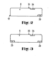
- Two versions of a folding door are shown in Figures 2 and 3. Each folding door has parts of a rotary connection on the two narrow sides, with the aid of which the folding door in the housing can be pivoted about an axis, in this case the longitudinal axis of the folding door, in an angular range.
- a bearing journal 17 is formed on the folding door 6, as can be seen in FIG. 2, which cooperates with a bore in the housing (not visible in FIG. 1) as the first pivot bearing.
- the second pivot bearing is formed, inter alia, by an opposing spring element which consists of a spring arm 23 which is partially cut free from the folding door, so that it can be deflected in a resilient manner. Since the folding door is long and narrow, the spring arm extends in the rotational axial direction. It would, of course, also be possible to arrange the spring arm vertically, that is to say parallel to the narrow side, but then, for design reasons, the folding door could not be made so narrow for the task.
- the second embodiment of the folding door shown in FIG. 3 has another spring arm instead of the bearing pin 17. If one compares the two embodiments, the folding door according to FIG. 2 is undoubtedly simpler.
- both embodiments of the folding door have a recess 24 in common on the long side, into which the finger of an operator can engage in order to be able to open the folding door better.
- FIGS. 4 to 8 Details of the rotary connection, in particular the spring arm 23, can be found in FIGS. 4 to 8. Between the spring arm 23 and the base part 26 of the folding door 6 there is a pivot pin 25 integrally formed on the housing 29. Another bevel 30 is provided on the base part 26 of the folding door for the same purpose. A recess 31 adjoins the bevel 30 in the base part, which has a profile that deviates from a semicircle. The pivot pin 25 is located in this recess. The spring arm holds the pivot pin in the recess. For this purpose, the distance between the spring arm and the base part without the snap-in pivot is slightly smaller than the diameter of the pivot. The spring arm is thus biased.
- FIGS. 7 and 8 show the folding door in the closed state.
- the spring arm 23 rests on the flat 33.
- the folding door is still kept closed by a molded-on projecting nose 35 in the housing. If you reach into the recess 24 with your finger and push the folding door slightly to the side, the folding door opens and it can be pivoted into the second latching position.
- This locking position is shown in FIG.
- the spring arm 23 now lies against the flat 34.
- the second latching position ensures that the folding door remains open even when the pushbutton unit is rotated through a right angle and installed in a television set with the axis of rotation at the top.
- the profile of the recess consists of a first segment 36 in the form of a segment of a circle and a second segment 37 adjoining it tangentially.
- This segment has an inclined surface which acts in the sense of a narrowing of the recess.
- the round part of the pivot pin 25 lies in the latching position in the first segment 36 in the form of a segment of a circle. If the folding door is now pushed aside to open it, the pivot pin slides along the inclined surface. The spring arm is thus bent open. If the finger pressure is released, the pivot pin slides back into the first section 36 due to the force exerted by the spring arm on the pivot pin.
- FIG. 1 Although only one row of pushbuttons is shown in FIG. 1, the invention can also be used with a row of multiple pushbuttons. To do this, only a window for e.g. a row of push buttons can be provided. Such an embodiment is shown in a perspective view in FIG.
Applications Claiming Priority (2)
| Application Number | Priority Date | Filing Date | Title |
|---|---|---|---|
| DE19813112753 DE3112753C2 (de) | 1981-03-31 | 1981-03-31 | Drucktastenaggregat |
| DE3112753 | 1981-03-31 |
Publications (2)
| Publication Number | Publication Date |
|---|---|
| EP0061622A1 true EP0061622A1 (fr) | 1982-10-06 |
| EP0061622B1 EP0061622B1 (fr) | 1985-02-13 |
Family
ID=6128839
Family Applications (1)
| Application Number | Title | Priority Date | Filing Date |
|---|---|---|---|
| EP19820101996 Expired EP0061622B1 (fr) | 1981-03-31 | 1982-03-12 | Ensemble à boutons-poussoir |
Country Status (3)
| Country | Link |
|---|---|
| EP (1) | EP0061622B1 (fr) |
| JP (1) | JPS57174922A (fr) |
| DE (1) | DE3112753C2 (fr) |
Cited By (7)
| Publication number | Priority date | Publication date | Assignee | Title |
|---|---|---|---|---|
| US4507820A (en) * | 1983-07-07 | 1985-04-02 | Purcocks Dale M | Concealable handle with a slidable pivot |
| EP0261906A2 (fr) * | 1986-09-22 | 1988-03-30 | Irvin Automotive Products, Inc. | Charnière à ressort pour accessoires de véhicules |
| US4796944A (en) * | 1986-09-22 | 1989-01-10 | Irvin Industries, Inc. | Spring-loaded hinge assembly for vehicle accessories |
| US4993772A (en) * | 1990-02-20 | 1991-02-19 | Irvin Automotive Products, Inc. | Spring-loaded, dual-action hinge assembly for vehicle accessories |
| USRE33610E (en) * | 1986-09-22 | 1991-06-11 | Takata Inc. | Spring-loaded hinge assembly for vehicle accessories |
| USRE33631E (en) * | 1986-09-22 | 1991-07-09 | Takata Inc. | Spring-loaded hinge assembly for vehicle accessories |
| CN107454500A (zh) * | 2017-09-22 | 2017-12-08 | 合肥惠科金扬科技有限公司 | 显示器外置音箱及其隐藏式挂接装置 |
Citations (7)
| Publication number | Priority date | Publication date | Assignee | Title |
|---|---|---|---|---|
| DE1911898A1 (de) * | 1969-03-08 | 1970-09-24 | Preh Elektro Feinmechanik | Kanalwahlaggregat fuer HF-Empfaenger |
| US3600743A (en) * | 1969-10-17 | 1971-08-24 | David Allison Co Inc | Self-closing hinge |
| DE1779273A1 (de) * | 1968-04-11 | 1971-09-09 | Edoardo Hunke & C S R L | Vorrichtung zum schnellen Auswechseln der Tueren von Schraenken,insbesondere Badezimmerschraenken |
| DE2163689A1 (de) * | 1971-12-22 | 1973-07-05 | Nordmende | Beruehrungsplatten tragendes oberflaechenteil eines elektronischen geraetes |
| GB1551827A (en) * | 1976-07-28 | 1979-09-05 | Mardon Illingworth | Hinge part for a lidded container and a lidded container incorporating the hinge part |
| DE2833184A1 (de) * | 1978-07-28 | 1980-02-07 | Preh Elektro Feinmechanik | Drucktastenaggregat |
| FR2458243A1 (fr) * | 1979-06-08 | 1981-01-02 | Oreal | Boitier en particulier poudrier de maquillage |
-
1981
- 1981-03-31 DE DE19813112753 patent/DE3112753C2/de not_active Expired
-
1982
- 1982-03-12 EP EP19820101996 patent/EP0061622B1/fr not_active Expired
- 1982-03-31 JP JP5145082A patent/JPS57174922A/ja active Pending
Patent Citations (7)
| Publication number | Priority date | Publication date | Assignee | Title |
|---|---|---|---|---|
| DE1779273A1 (de) * | 1968-04-11 | 1971-09-09 | Edoardo Hunke & C S R L | Vorrichtung zum schnellen Auswechseln der Tueren von Schraenken,insbesondere Badezimmerschraenken |
| DE1911898A1 (de) * | 1969-03-08 | 1970-09-24 | Preh Elektro Feinmechanik | Kanalwahlaggregat fuer HF-Empfaenger |
| US3600743A (en) * | 1969-10-17 | 1971-08-24 | David Allison Co Inc | Self-closing hinge |
| DE2163689A1 (de) * | 1971-12-22 | 1973-07-05 | Nordmende | Beruehrungsplatten tragendes oberflaechenteil eines elektronischen geraetes |
| GB1551827A (en) * | 1976-07-28 | 1979-09-05 | Mardon Illingworth | Hinge part for a lidded container and a lidded container incorporating the hinge part |
| DE2833184A1 (de) * | 1978-07-28 | 1980-02-07 | Preh Elektro Feinmechanik | Drucktastenaggregat |
| FR2458243A1 (fr) * | 1979-06-08 | 1981-01-02 | Oreal | Boitier en particulier poudrier de maquillage |
Cited By (9)
| Publication number | Priority date | Publication date | Assignee | Title |
|---|---|---|---|---|
| US4507820A (en) * | 1983-07-07 | 1985-04-02 | Purcocks Dale M | Concealable handle with a slidable pivot |
| EP0261906A2 (fr) * | 1986-09-22 | 1988-03-30 | Irvin Automotive Products, Inc. | Charnière à ressort pour accessoires de véhicules |
| EP0261906A3 (fr) * | 1986-09-22 | 1988-07-27 | Irvin Automotive Products, Inc. | Charnière à ressort pour accessoires de véhicules |
| US4796944A (en) * | 1986-09-22 | 1989-01-10 | Irvin Industries, Inc. | Spring-loaded hinge assembly for vehicle accessories |
| USRE33610E (en) * | 1986-09-22 | 1991-06-11 | Takata Inc. | Spring-loaded hinge assembly for vehicle accessories |
| USRE33631E (en) * | 1986-09-22 | 1991-07-09 | Takata Inc. | Spring-loaded hinge assembly for vehicle accessories |
| US4993772A (en) * | 1990-02-20 | 1991-02-19 | Irvin Automotive Products, Inc. | Spring-loaded, dual-action hinge assembly for vehicle accessories |
| CN107454500A (zh) * | 2017-09-22 | 2017-12-08 | 合肥惠科金扬科技有限公司 | 显示器外置音箱及其隐藏式挂接装置 |
| CN107454500B (zh) * | 2017-09-22 | 2023-04-18 | 合肥惠科金扬科技有限公司 | 显示器外置音箱及其隐藏式挂接装置 |
Also Published As
| Publication number | Publication date |
|---|---|
| DE3112753A1 (de) | 1982-11-11 |
| JPS57174922A (en) | 1982-10-27 |
| DE3112753C2 (de) | 1985-09-05 |
| EP0061622B1 (fr) | 1985-02-13 |
Similar Documents
| Publication | Publication Date | Title |
|---|---|---|
| DE102006024994B3 (de) | Elektronischer Schalter | |
| EP0061622B1 (fr) | Ensemble à boutons-poussoir | |
| DE4212838C2 (de) | Schaltervorrichtung | |
| EP0050202B1 (fr) | Ensemble de boutons-poussoirs | |
| EP0024620B1 (fr) | Touche lumineuse pour claviers de machines de bureau et téléscripteurs | |
| EP0199983A1 (fr) | Commutateur électrique | |
| EP0160791A1 (fr) | Commutateur à bouton-poussoir | |
| DE2833184C2 (de) | Drucktastenaggregat | |
| DE3835073C2 (de) | Elektrischer Schalter für eine Kraftfahrzeug-Fensterhebevorrichtung | |
| DE6905921U (de) | Druckknopfschalteranordnung | |
| EP1168395A2 (fr) | Dispositif de commutation electrique | |
| DE3626242A1 (de) | Schalter, insbesondere lenkstockschalter fuer kraftfahrzeuge | |
| EP3884554B1 (fr) | Appareil d'installation électrique | |
| DE3109868A1 (de) | Drucktastenaggregat | |
| DE3018810C2 (fr) | ||
| EP0050201B1 (fr) | Ensemble de boutons-poussoirs | |
| DE3332191A1 (de) | Innenleuchte mit wippenschalter | |
| DE1933976A1 (de) | Abstimmvorrichtung fuer HF-Nachrichten-UEbertragungsgeraete | |
| DE3129004A1 (de) | Schalteranordnung fuer fahrzeuge | |
| DE3209913C2 (de) | Drucktastenaggregat | |
| DE2102385A1 (de) | Tastenschalter-Tableau-Mechanik | |
| DE3015292A1 (de) | Drucktastenaggregat | |
| DE2240932C3 (de) | Frequenzbandspeicheranordnung für Rundfunkempfänger mit Stationsdrucktasten | |
| DE1100135B (de) | Elektrischer Kipphebelschalter | |
| DE3238612A1 (de) | Nachrichtengeraet mit drucktastenaggregat |
Legal Events
| Date | Code | Title | Description |
|---|---|---|---|
| PUAI | Public reference made under article 153(3) epc to a published international application that has entered the european phase |
Free format text: ORIGINAL CODE: 0009012 |
|
| AK | Designated contracting states |
Designated state(s): FR GB IT |
|
| 17P | Request for examination filed |
Effective date: 19830509 |
|
| ITF | It: translation for a ep patent filed |
Owner name: DR. ING. A. RACHELI & C. |
|
| GRAA | (expected) grant |
Free format text: ORIGINAL CODE: 0009210 |
|
| AK | Designated contracting states |
Designated state(s): FR GB IT |
|
| ET | Fr: translation filed | ||
| PLBE | No opposition filed within time limit |
Free format text: ORIGINAL CODE: 0009261 |
|
| STAA | Information on the status of an ep patent application or granted ep patent |
Free format text: STATUS: NO OPPOSITION FILED WITHIN TIME LIMIT |
|
| 26N | No opposition filed | ||
| PGFP | Annual fee paid to national office [announced via postgrant information from national office to epo] |
Ref country code: GB Payment date: 19890228 Year of fee payment: 8 |
|
| PGFP | Annual fee paid to national office [announced via postgrant information from national office to epo] |
Ref country code: FR Payment date: 19890302 Year of fee payment: 8 |
|
| ITTA | It: last paid annual fee | ||
| PG25 | Lapsed in a contracting state [announced via postgrant information from national office to epo] |
Ref country code: GB Effective date: 19900312 |
|
| GBPC | Gb: european patent ceased through non-payment of renewal fee | ||
| PG25 | Lapsed in a contracting state [announced via postgrant information from national office to epo] |
Ref country code: FR Effective date: 19901130 |
|
| REG | Reference to a national code |
Ref country code: FR Ref legal event code: ST |