EP0061622A1 - Push-button unit - Google Patents
Push-button unit Download PDFInfo
- Publication number
- EP0061622A1 EP0061622A1 EP82101996A EP82101996A EP0061622A1 EP 0061622 A1 EP0061622 A1 EP 0061622A1 EP 82101996 A EP82101996 A EP 82101996A EP 82101996 A EP82101996 A EP 82101996A EP 0061622 A1 EP0061622 A1 EP 0061622A1
- Authority
- EP
- European Patent Office
- Prior art keywords
- folding door
- housing
- recess
- door
- spring arm
- Prior art date
- Legal status (The legal status is an assumption and is not a legal conclusion. Google has not performed a legal analysis and makes no representation as to the accuracy of the status listed.)
- Granted
Links
Images


Classifications
-
- H—ELECTRICITY
- H03—ELECTRONIC CIRCUITRY
- H03J—TUNING RESONANT CIRCUITS; SELECTING RESONANT CIRCUITS
- H03J1/00—Details of adjusting, driving, indicating, or mechanical control arrangements for resonant circuits in general
- H03J1/06—Driving or adjusting arrangements; combined with other driving or adjusting arrangements, e.g. of gain control
- H03J1/066—Constructional details regarding potentiometric setting of voltage or current variable reactances
-
- E—FIXED CONSTRUCTIONS
- E05—LOCKS; KEYS; WINDOW OR DOOR FITTINGS; SAFES
- E05D—HINGES OR SUSPENSION DEVICES FOR DOORS, WINDOWS OR WINGS
- E05D11/00—Additional features or accessories of hinges
- E05D11/10—Devices for preventing movement between relatively-movable hinge parts
- E05D11/1028—Devices for preventing movement between relatively-movable hinge parts for maintaining the hinge in two or more positions, e.g. intermediate or fully open
- E05D11/105—Devices for preventing movement between relatively-movable hinge parts for maintaining the hinge in two or more positions, e.g. intermediate or fully open the maintaining means acting perpendicularly to the pivot axis
-
- E—FIXED CONSTRUCTIONS
- E05—LOCKS; KEYS; WINDOW OR DOOR FITTINGS; SAFES
- E05Y—INDEXING SCHEME RELATING TO HINGES OR OTHER SUSPENSION DEVICES FOR DOORS, WINDOWS OR WINGS AND DEVICES FOR MOVING WINGS INTO OPEN OR CLOSED POSITION, CHECKS FOR WINGS AND WING FITTINGS NOT OTHERWISE PROVIDED FOR, CONCERNED WITH THE FUNCTIONING OF THE WING
- E05Y2900/00—Application of doors, windows, wings or fittings thereof
- E05Y2900/20—Application of doors, windows, wings or fittings thereof for furnitures, e.g. cabinets
Definitions
- the invention is based on a pushbutton unit according to the preamble of claim 1.
- Such pushbutton assemblies are preferred in various embodiments when tuning and switching on RF receivers, such as Television receivers.
- the preset tuning voltage and thus the assigned station or channel can be switched on by pressing a single button.
- the set tuning voltage is stored in channel memories in the form of spindle resistors or rotary resistors connected as voltage dividers.
- the channel memories and their display means, as well as any setting elements provided for preselecting the frequency range, should not and should not be directly accessible during normal operation of the device, since they can easily lead to an unintentional or unintended incorrect operation of the device.
- the appearance of the device can be adversely affected with an increasing number of push buttons.
- each channel memory is accommodated in a pocket or in a somewhat recessed recess and each channel memory is provided with a cover designed in the form of a large pushbutton.
- This cover is resiliently resettable, rotatable and hinged and it rests on the switch-on member so that it can be actuated by pressing the closed cover. Since the switch-on element also serves for tuning in addition to its switching function, the switch-on elements must have a relatively large mutual lateral spacing so that the switch-on elements, which are located deep in the pressed state and which are also used for tuning, can still be turned comfortably with the finger.
- a smaller installation width requires another known pushbutton unit (JE-AS 1 911 898), in which the pushbuttons for channel activation can be operated by means of individual buttons which are pivotally mounted in a folding door common to all pushbuttons.
- the frequency range can only be selected when the folding door is open.
- a metal rail is attached to one of the long sides, the end journals of which cooperate with a metal bracket, which are in turn fastened in the housing of the pushbutton unit. This additional constructive effort is intended to prevent the hinged door from breaking out on its hinges.
- Leaf spring tongues made of metal are attached in the side wall of the housing below Liger openings in the folding door, which with their protruding free tongue ends into the bearing openings.
- the leaf spring tongues exert a torque in a clockwise direction on the buttons and also on the flap door, so that the buttons rest with light pressure on the push buttons and the flap door is pressed onto the housing.
- the folding door is pivoted counterclockwise. The tongue ends then lay against the beveled surfaces of the folding door with prestress, so that the folding door is held in this position with a slight latching force.
- the object of the present invention is to find a rotary connection for the folding door for a pushbutton unit of the type mentioned at the outset, which is simple and cost-saving to manufacture and which is particularly suitable for a folding door with a small width.
- the pushbutton assembly shown in FIG. 1 in perspective view and designated 1 has a number of eight pushbuttons 4 that can be triggered mutually by means of a locking rail for switching on the tuning voltages preset in the individual channel memories.
- the pushbutton unit 1 consists essentially of a memory housing 2 and a housing front 3 with setting, switching and display elements.
- the individual adjusting elements for the volume, brightness, contrast, etc. consist of several rotary resistors with their associated knobs 7, which are arranged laterally to the row of push buttons.
- the rotating resistors sliding resistors can also be used. It goes without saying that the arrangement of the adjusting elements, be it sliding or rotational resistances, is also possible above or below the row of push buttons.
- the invisible push buttons for setting the tuning voltages should not be directly accessible during normal operation of the device, they are located in a recess 8 on the front side 3 of the housing.
- This recess 8 is covered by a cover covered. This is to prevent the device from being operated incorrectly or unintentionally.
- the cover is a folding door 6.
- the storage housing 2 is arranged behind the housing front 3.
- the tuning voltage is set by the position of the spring bracket.
- the individual resistors are applied side by side on an insulating plate 9, which is held in the storage housing.
- each spindle has a push-button that protrudes into the recess on the front of the housing and is provided with a ribbed or otherwise non-slip edge - if manual operation is performed without tools.
- the pushbutton also has a cavity that has a certain inner profile. To tune a socket 10 is inserted into this cavity, which is also the switch plunger for an AFC switch.
- the switching tappets can also be used to select the frequency range. To do this, the push button must only be pressed and then turned to one of the switch positions.
- the AFC switch consists of a first fixed contact piece 11, which is made of wire.
- the second contact piece 12 is also made of wire.
- This second contact piece is designed with two arms, one arm being formed by the pivotable contact element. In addition to the contacting, this contact element also serves to push the socket wrench 10 out of the housing so far when the folding door 6 is opened that it can be pulled out completely with the finger.
- the other arm is formed by a fixed connector. Both arms are connected to one another by eyelet-shaped windings which lie around an integrally formed pin 13 which represents a type of abutment for the second contact piece.
- the stationary connector is still supported in a slot of a molded bracket.
- the pushbuttons 4 are used to switch on the channel, one end being guided in a guide in the rear longitudinal wall 14 of the storage housing 2.
- the other end, which is guided in the front longitudinal wall, carries on its front end protruding from the storage housing the actuating button 5, which is pressed onto the push button in a press fit or which is integrally molded directly onto the push button.
- Each pushbutton is held in the storage housing and limited in its direction of displacement by a retaining lug and a stop.
- the push button assembly shown in Figure 1 is intended to be used in particular in television receivers. For this it is necessary that the frequency range switchover is carried out in addition to the channel switch-on. That is why two independent contact systems are actuated with the push button.
- each leaf spring is J-shaped with a long and a short spring arm, both of which are integrally connected to one another via an arcuate intermediate piece.
- This leaf spring is clamped between two abutments in such a way that it is slightly curved on one side. This is achieved, among other things, by not aligning the two abutments with one another.
- the leaf spring fulfills a double function since it is a contact spring on the one hand, but also a return spring for the pushbutton on the other.
- the long spring arm essentially takes over the function of the return spring, while the short spring arm serves as a contact arm.
- the push button is very easy to operate. Since only the buckling force of the already bulging long, relatively soft spring arm has to be overcome when the pushbutton is pressed, to which the contact pressure of the short spring arm is added to a stationary contact piece, but this contact force is reduced in relation to the distances between the action points.
- the pushbutton unit is equipped with a light indicator device.
- a light indicator device This consists of several light guides, which are guided in a star shape from a lighting center to the individual pushbuttons and whose ends 18 are visible in an opening in the front of the housing.
- the lighting center itself consists of a socket 19 made of transparent plastic, in the cavity 20 of which a lamp 21 is inserted.
- the light guides are made of a transparent, clear plastic, so that the visible ends 18 appear bright or white when the push button is pressed.
- a colored display In principle, a colored plastic could be used. However, it is easier to take a special ink carrier that is inserted between the lamp and the socket in the cavity. If all pushbuttons are to have the same color display, it is sufficient to take an annular ink carrier 22 which is of a single color.
- the illuminated display device is composed of two parts, a first part 15 and a second part 16.
- the first part has the light center with the socket 19 and the lamp 21. From this light center, light guides lead, the number of which corresponds to the number of pushbuttons.
- all light guides are connected to one another by a first retaining web, which also serves to fasten the first part to the storage housing.
- the second part of the light display device essentially consists of parallel light guides, the ends 18 of which are visible in the openings on the front of the housing. These light guides are connected by a second holding bridge. There is an air gap between the first and the second part, into which the rear part of the flat key slide 32 projects. This rear part consists of a panel wall and a window.
- the panel wall protrudes into the air gap.
- the light guidance is thus interrupted.
- the window projects into the air gap and the light can cross the air gap unhindered, so that the end 18 lights up.
- all push buttons are in a row, so that the light guides are only in one plane.
- the light guides must also be arranged in two rows.
- an additional part is plugged onto the first part 15. This consists of a sleeve-shaped base part which is pressed onto the socket 19.
- Several light guides are led away from the base part via curved and straight sections and via bends.
- the lamp housed in the socket supplies both the light guides on the first level and the light guides on the second level.
- the additional part is fastened in the housing by a third retaining web. So there is an easy way to expand.
- the recess 8 is long and narrow.
- the flap door 6 is also long and narrow.
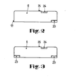
- Two versions of a folding door are shown in Figures 2 and 3. Each folding door has parts of a rotary connection on the two narrow sides, with the aid of which the folding door in the housing can be pivoted about an axis, in this case the longitudinal axis of the folding door, in an angular range.
- a bearing journal 17 is formed on the folding door 6, as can be seen in FIG. 2, which cooperates with a bore in the housing (not visible in FIG. 1) as the first pivot bearing.
- the second pivot bearing is formed, inter alia, by an opposing spring element which consists of a spring arm 23 which is partially cut free from the folding door, so that it can be deflected in a resilient manner. Since the folding door is long and narrow, the spring arm extends in the rotational axial direction. It would, of course, also be possible to arrange the spring arm vertically, that is to say parallel to the narrow side, but then, for design reasons, the folding door could not be made so narrow for the task.
- the second embodiment of the folding door shown in FIG. 3 has another spring arm instead of the bearing pin 17. If one compares the two embodiments, the folding door according to FIG. 2 is undoubtedly simpler.
- both embodiments of the folding door have a recess 24 in common on the long side, into which the finger of an operator can engage in order to be able to open the folding door better.
- FIGS. 4 to 8 Details of the rotary connection, in particular the spring arm 23, can be found in FIGS. 4 to 8. Between the spring arm 23 and the base part 26 of the folding door 6 there is a pivot pin 25 integrally formed on the housing 29. Another bevel 30 is provided on the base part 26 of the folding door for the same purpose. A recess 31 adjoins the bevel 30 in the base part, which has a profile that deviates from a semicircle. The pivot pin 25 is located in this recess. The spring arm holds the pivot pin in the recess. For this purpose, the distance between the spring arm and the base part without the snap-in pivot is slightly smaller than the diameter of the pivot. The spring arm is thus biased.
- FIGS. 7 and 8 show the folding door in the closed state.
- the spring arm 23 rests on the flat 33.
- the folding door is still kept closed by a molded-on projecting nose 35 in the housing. If you reach into the recess 24 with your finger and push the folding door slightly to the side, the folding door opens and it can be pivoted into the second latching position.
- This locking position is shown in FIG.
- the spring arm 23 now lies against the flat 34.
- the second latching position ensures that the folding door remains open even when the pushbutton unit is rotated through a right angle and installed in a television set with the axis of rotation at the top.
- the profile of the recess consists of a first segment 36 in the form of a segment of a circle and a second segment 37 adjoining it tangentially.
- This segment has an inclined surface which acts in the sense of a narrowing of the recess.
- the round part of the pivot pin 25 lies in the latching position in the first segment 36 in the form of a segment of a circle. If the folding door is now pushed aside to open it, the pivot pin slides along the inclined surface. The spring arm is thus bent open. If the finger pressure is released, the pivot pin slides back into the first section 36 due to the force exerted by the spring arm on the pivot pin.
- FIG. 1 Although only one row of pushbuttons is shown in FIG. 1, the invention can also be used with a row of multiple pushbuttons. To do this, only a window for e.g. a row of push buttons can be provided. Such an embodiment is shown in a perspective view in FIG.
Landscapes
- Engineering & Computer Science (AREA)
- Mechanical Engineering (AREA)
- Casings For Electric Apparatus (AREA)
- Rotary Switch, Piano Key Switch, And Lever Switch (AREA)
Abstract
Description
Die Erfindung geht von einem Drucktastenaggregat nach dem Oberbegriff des Anspruches 1 aus.The invention is based on a pushbutton unit according to the preamble of claim 1.
Derartige Drucktastenaggregate werden in verschiedenen Ausführungsformen bevorzugt bei der Abstimmung und Einschaltung von HF-Empfängern, wie z.B. Fernsehempfängern, eingesetzt. Durch einen einzigen'Tastendruck kann jeweils die voreingestellte Abstimmspannung und damit die zugeordnete Station bzw. der Kanal eingeschaltet werden. Die Speicherung der eingestellten Abstimmspannung erfolgt in Kanalspeichern in der Form von als Spannungsteiler geschalteten Spindelwiderständen oder Drehwiderständen. Die Kanalspeicher und deren Anzeigemittel sowie eventuell zur Frequenzbereichsvorwahl vorgesehene Einstellorgane brauchen und sollen im Normalbetrieb des Gerätes nicht unmittelbar zugänglich sein, da sie leicht zu einer unwissentlichen oder unbeabsichtigten Fehlbedienung des Gerätes führen können. Außerdem kann bei zunehmender Zahl der Druckdrehknöpfe das Aussehen des Gerätes ungünstig beeinflußt werden. Man ist daher dazu übergegangen, die Einstellorgane in Vertiefungen des Gehäuses unterzubringen und diese Vertiefungen durch Abdeckungen in der Form von Klapptüren zu verschließen. Es besteht ferner der Trend, möglichst viele Druckdrehknöpfe zur Verfügung zu haben. Andererseits ist der auf der Frontseite der Fernsehempfänger vorhandene Platz meist sehr beschränkt. Dies bedeutet letztlich, daß der Abstand der Druckdrehknöpfe immer kleiner wird. Der seitliche Abstand kann aber ein bestimmtes Maß nicht unterschreiten, da die im gedrückten Zustand tief liegenden Einstellorgane, die ja gleichzeitig auch zur Abstimmung dienen, noch bequem mit den Fingern gedreht werden sollen. Um den seitlichen Abstand trotzdem noch verringern zu können, hat man den Einsatz eines Hilfsmittels in der Form eines Steckschlüssels vorgesehen.Such pushbutton assemblies are preferred in various embodiments when tuning and switching on RF receivers, such as Television receivers. The preset tuning voltage and thus the assigned station or channel can be switched on by pressing a single button. The set tuning voltage is stored in channel memories in the form of spindle resistors or rotary resistors connected as voltage dividers. The channel memories and their display means, as well as any setting elements provided for preselecting the frequency range, should not and should not be directly accessible during normal operation of the device, since they can easily lead to an unintentional or unintended incorrect operation of the device. In addition, the appearance of the device can be adversely affected with an increasing number of push buttons. It has therefore started to accommodate the adjusting members in recesses in the housing and to close these recesses by covers in the form of folding doors. There is also a trend to have as many push buttons available. On the other hand, the space available on the front of the television receiver is usually very limited. Ultimately, this means that the distance between the push buttons becomes smaller and smaller. The lateral distance, however, cannot be less than a certain dimension, since the setting elements, which are located deep in the pressed state and are also used for tuning, should still be turned with the fingers. In order to still be able to reduce the lateral distance, the use of an aid in the form of a socket wrench has been provided.
Es ist bereits bekannt (DE-Zeitschrift Funkschau 1968, Heft 10, S. 306), das Drucktastenaggregat in Form eines Einschubes auszubilden, auf dessen auch in eingeschobenem Zustand zugänglichen Stirnseite die Drucktasten für die Schalter angebracht sind, während die Abstimmhandhaben für die Spannungsteiler und für die Bereichswahlorgane erst nach Herausziehen des Aggregates aus dem Gerät bedient werden können. Eine derartige Anordnung ist jedoch wegen der im Gerät erforderlichen Führungen für den Einschub und wegen seiner beweglichen Zuleitungen recht aufwendig und mit Unsicherheitsfaktoren behaftet.It is already known (DE magazine Funkschau 1968,
Es ist ferner bereits aus der DE-AS 1 591 713 ein Drucktastenaggregat bekannt, bei dem jeder Kanalspeicher in einer Tasche bzw. in einer etwas vertieften Aussparung untergebracht ist und wobei jeder Kanalspeicher mit einem in Form einer großen Drucktaste ausgebildeten Deckel versehen ist. Dieser Deckel ist federnd rückstellend,dreh- und aufklappbar und er liegt so auf dem Einschaltorgan auf, daß dieses durch Druck auf den geschlossenen Deckel betätigt werden kann. Da das Einschaltorgan neben seiner Schaltfunktion auch noch zur Abstimmung dient, müssen die Einschaltorgane einen relativ großen gegenseitigen seitlichen Abstand besitzen, damit die im gedrückten Zustand tief liegenden Einschaltorgane, die ja gleichzeitig auch zur Abstimnung dienen, noch bequem mit dem Finger gedreht werden können.It is also already known from DE-AS 1 591 713 a pushbutton unit in which each channel memory is accommodated in a pocket or in a somewhat recessed recess and each channel memory is provided with a cover designed in the form of a large pushbutton. This cover is resiliently resettable, rotatable and hinged and it rests on the switch-on member so that it can be actuated by pressing the closed cover. Since the switch-on element also serves for tuning in addition to its switching function, the switch-on elements must have a relatively large mutual lateral spacing so that the switch-on elements, which are located deep in the pressed state and which are also used for tuning, can still be turned comfortably with the finger.
Eine geringere Einbaubreite benötigt bei gleicher Anzahl der Druckdrehknöpfe ein weiteres bekanntes Drucktastenaggregat (JE-AS 1 911 898), bei dem die Druckdrehknöpfe zur Kanaleinschaltung mttels einzelner Tasten betätigbar sind, die in einer allen Druckdr:hknöpfen gemeinsamen Klapptür schwenkbar gelagert sind. Die Frequenzbereichswahl kann nur bei geöffneter Klapptür vorgenommen werden. Im Rahmen der aus Kunststoff hergestellten Klapptür ist an einer der Längsseiten eine Metallschiene befestigt, deren endseitige Lagerzapfen mit je einer Metallhalterung zusammenwirken, die ihrerseits im Gehäuse des Drucktastenaggregates befestigt sind. Dieser kontruktive Mehraufwand soll verhindern, daß die Klapptür an ihren Schariieren ausbricht. In der Seitenwand des Gehäuses sind unterhalb von Ligerdurchbrüchen in der Klapptür Blattfederzungen aus Metall befestig, die mit ihren freien Zungenenden in die Lagerdurchbrüche hineinragen. Bei geschlossener Klapptür liegen die Zungenenden auf der Innenseite der Tasten unter Vorspannung an. Die Blattfederzungen üben auf die Tasten und auch auf die Klapptür ein Drehmoment im Uhrzeigersinn aus, so daß die Tasten mit leichtem Druck auf den Druckdrehknöpfen aufliegen und die Klapptür auf das Gehäuse gedrückt wird. Zur Veränderung der Kanalabstimmung wird die Klapptür entgegen dem Uhrzeigersinn geschwenkt. Die Zungenenden legen sich dann mit Vorspannung an abgeschrägte Flächen der Klapptür an, so daß die Klapptür mit einer leichten Rastkraft in dieser Stellung gehalten wird.With the same number of pushbuttons, a smaller installation width requires another known pushbutton unit (JE-AS 1 911 898), in which the pushbuttons for channel activation can be operated by means of individual buttons which are pivotally mounted in a folding door common to all pushbuttons. The frequency range can only be selected when the folding door is open. In the context of the hinged door made of plastic, a metal rail is attached to one of the long sides, the end journals of which cooperate with a metal bracket, which are in turn fastened in the housing of the pushbutton unit. This additional constructive effort is intended to prevent the hinged door from breaking out on its hinges. Leaf spring tongues made of metal are attached in the side wall of the housing below Liger openings in the folding door, which with their protruding free tongue ends into the bearing openings. When the hinged door is closed, the tongue ends are pressed against the inside of the buttons. The leaf spring tongues exert a torque in a clockwise direction on the buttons and also on the flap door, so that the buttons rest with light pressure on the push buttons and the flap door is pressed onto the housing. To change the channel tuning, the folding door is pivoted counterclockwise. The tongue ends then lay against the beveled surfaces of the folding door with prestress, so that the folding door is held in this position with a slight latching force.
Aufgabe der vorliegenden Erfindung ist es, für ein Drucktastenaggregat nach der eingangs genannten Art eine Drehverbindung für die Klapptür zu finden, die einfach und kostensparend herzustellen ist und die insbesondere für eine Klapptür mit einer geringen Breite geeignet ist.The object of the present invention is to find a rotary connection for the folding door for a pushbutton unit of the type mentioned at the outset, which is simple and cost-saving to manufacture and which is particularly suitable for a folding door with a small width.
Diese Aufgabe wird erfindungsgemäß durch die im kennzeichnenden Teil des Patentanspruches 1 angegebenen Merkmale gelöst.This object is achieved by the features specified in the characterizing part of claim 1.
Weitere vorteilhafte Ausgestaltungen der Erfindung sind den Unteransprüchen zu entnehmen.Further advantageous embodiments of the invention can be found in the subclaims.
Die Verwendung einer Klapptür mit einer geringen Breite erlaubt es, die Vertiefung lang und schmal auszuführen. Dies kommt dem Bestreben entgegen, Drucktastenaggregate möglichst mit geringem Platzbedarf auf der Frontseite der Geräte durch einen räumlich gedrängten Aufbau ohne Verlust der leichten Bedienbarkeit zu konstruieren. Es ist auch leicht möglich, nebeneinander in zwei Vertiefungen liegende Reihen von Drehknöpfen mit nur einer Klapptür abdecken zu können.The use of a folding door with a small width allows the recess to be made long and narrow. This complies with the endeavor to construct pushbutton assemblies with as little space as possible on the front of the devices by means of a spatially compact structure without loss of ease of use. It is also easily possible to be able to cover rows of knobs lying side by side in two recesses with just one hinged door.
Einzelheiten der Erfindung werden nachfolgend für ein Beispiel anhand der Zeichnungen näher erläutert.Details of the invention are explained below for an example with reference to the drawings.
Von den Figuren zeigt
- Figur eine perspektivische Ansicht eines Drucktastenaggregates,
Figur 2 die Rückansicht einer Klapptür,Figur 3 die Rückansicht einer anderen Klapptür,- Figur 4 im vergrößerten Maßstab eine Seitenansicht der Klapptür teilweise im Schnitt,
Figur 5 im vergrößerten Maßstab das Federelement der Klapptür im Schnitt,Figur 6 im vergrößerten Maßstab das Federelement der Klapptür in der Draufsicht,Figur 7 im vergrößerten Maßstab die Drehverbindung Klapptür/Gehäuse bei geschlossener Klapptür,Figur 8 im vergrößerten Maßstab die Drehverbindung Klapptür/Gehäuse bei offener Klapptür,Figur 9 eine perspektivische Ansicht eines Drucktastenaggregates mit zwei Drucktastenreihen.
- FIG. 1 shows a perspective view of a pushbutton unit,
- FIG. 2 shows the rear view of a folding door,
- FIG. 3 shows the rear view of another folding door,
- FIG. 4 shows an enlarged side view of the folding door, partly in section,
- FIG. 5 shows the spring element of the folding door in section on an enlarged scale,
- FIG. 6, on an enlarged scale, the spring element of the folding door in a top view,
- FIG. 7, on an enlarged scale, the rotary connection of the folding door / housing with the folding door closed,
- FIG. 8, on an enlarged scale, the rotary connection of the folding door / housing with the folding door open,
- Figure 9 is a perspective view of a push button assembly with two rows of push buttons.
Das in Figur 1 in perspektivischer Ansicht dargestellte und mit 1 bezeichnete Drucktastenaggregat besitzt eine Reihe von acht mittels einer Sperrschiene gegenseitig auslösbaren Drucktasten 4 zur Einschaltung der in den einzelnen Kanalspeichern voreingestellten Abstimmspannungen. Selbstverständlich ist auch eine hiervon abweichende Anzahl von Drucktasten denkbar. Das Drucktastenaggregat 1 besteht im wesentlichen aus einem Speichergehäuse 2 und einer Gehäusefrontseite 3 mit Einstell-, Schalt- und Anzeigeorganen.The pushbutton assembly shown in FIG. 1 in perspective view and designated 1 has a number of eight pushbuttons 4 that can be triggered mutually by means of a locking rail for switching on the tuning voltages preset in the individual channel memories. Of course, a different number of push buttons is also conceivable. The pushbutton unit 1 consists essentially of a
Bei dem in Figur 1 dargestellten Ausführungsbeispiel bestehen die einzelnen Einstellorgane für die Lautstärke, Bildhelligkeit, Kontrast usw. aus mehreren Drehwiderständen mit ihren zugeordneten Drehknöpfen 7, die seitlich zu der Drucktastenreihe angeordnet sind. Anstelle der Drehwiderstände können auch Schiebewiderstände Verwendung finden. Es ist hierbei selbstverständlich, daß die Anordnung der Einstellorgane, seien es nun Schiebe- oder Drehwiderstände, auch ober- oder unterhalb der Drucktastenreihe möglich ist.In the embodiment shown in Figure 1, the individual adjusting elements for the volume, brightness, contrast, etc. consist of several rotary resistors with their associated
Da die nicht sichtbaren Druckdrehknöpfe für die Einstellung der Abstimmspannungen im Normalbetrieb des Gerätes nicht unmittelbar zugänglich sein sollen, befinden sich diese in einer Vertiefung 8 der Gehäuseforntseite 3. Diese Vertiefung 8 ist durch eine Abdeckung verdeckt. Hierdurch soll eine unwissentliche oder unbeabsichtigte Fehlbedienung des Gerätes vermieden werden. Die Abdeckung ist eine Klapptür 6.Since the invisible push buttons for setting the tuning voltages should not be directly accessible during normal operation of the device, they are located in a
Hinter der Gehäusefrontseite 3 ist das Speichergehäuse 2 angeordnet. In diesem befinden sich Spindelwiderstände, die die Kanalspeicher darstellen. Diese bestehen jeweils aus einer Spindel, auf der ein Federträger entlanggeführt ist, auf dem eine Schleiffeder befestigt ist, die zwischen Widerstand und Spindel eine elektrische Verbindung herstellt. Durch die Stellung des Federträgers wird die Abstimmspannung eingestellt. Die einzelnen Widerstände sind nebeneinander auf einer Isolierstoffplatte 9 aufgebracht, die im Speichergehäuse gehaltert ist. An einem Ende weist jede Spindel einen Druckdrehknopf auf, der in die Vertiefung der Gehäusefrontseite ragt und der mit einer geriffelten oder sonstwie griffig gestalteten Randung - falls Handbedienung ohne Hilfsmittel erfolgt - versehen ist. Der Druckdrehknopf besitzt außerdem eine Höhlung, die ein bestimmtes Innenprofil aufweist. Zur Abstimmung wird ein Steckschlüssel 10 in diese Höhlung gesteckt, der gleichzeitig der Schaltstößel für einen AFC-Schalter ist. Mit dem Schaltstößel können außerdem auch die Schaltorgane für die Frequenzbereichswahl betätigt werden. Hierzu muß.der Druckdrehknopf lediglich gedrückt und anschließend in eine der Schaltpositionen gedreht werden.The
Der AFC-Schalter besteht aus einem ersten ortsfesten Kontaktstück 11, das aus Draht hergestellt ist. Ebenfalls aus Draht hergestellt ist das zweite Kontaktstück 12. Dieses zweite Kontaktstück ist zweiarmig ausgebildet, wobei ein Arm von dem schwenkbaren Kontaktelement gebildet wird. Dieses Kontaktelement dient neben der Kontaktierung noch dazu, den Steckschlüssel 10 beim öffnen der Klapptür 6 aus dem Gehäuse soweit herauszudrücken, daß er bequem mit dem Finger ganz herausgezogen werden kann. Der andere Arm wird durch ein ortsfestes Anschlußstück gebildet. Beide Arme sind durch ösenförmige Windungen miteinander verbunden, die um einen angeformten Zapfen 13 liegen, der eine Art Widerlager für das zweite Kontaktstück darstellt. Darüberhinaus stützt sich das ortsfeste Anschlußstück noch in einem Schlitz einer angeformten Halterung ab. Immer dann, wenn die Abstimmspannung mit Hilfe des Steckschlüssels neu eingestellt wird, wird durch die Herausnahme des Steckschlüssels aus dem Drucktastenaggregat der AFC-Schalter ausgeschaltet. Ist die Klapptür 6 jedoch geschlossen, so ist der AFC-Schalter eingeschaltet, so daß eine automatische Frequenzregelung wirksam werden kann.The AFC switch consists of a first fixed contact piece 11, which is made of wire. The
Zur Kanaleinschaltung dienen die Drucktasten 4, wobei ein Ende in der hinteren Längswand 14 des Speichergehäuses 2 in einer Führung geführt ist. Das andere Ende, das in der vorderen Längswand geführt ist, trägt an seiner aus dem Speichergehäuse herausragenden Stirnseite den Betätigungsknopf 5, der im Preßsitz auf die Drucktaste aufgedrückt ist oder der direkt an die Drucktaste einstückig angespritzt ist. Durch eine Haltenase und durch einen Anschlag ist jede Drucktaste in dem Speichergehäuse gehaltert und in seiner Verschieberichtung begrenzt. Das in Figur 1 dargestellte Drucktastenaggregat soll insbesondere in Fernsehempfängern eingesetzt werden. Hierzu ist es erforderlich, daß neben der Kanaleinschaltung noch die Frequenzbereichsumschaltung vorgenommen wird. Deshalb werden mit der Drucktaste zwei voneinander unabhängige Kontaktsysteme betätigt. Aus diesem Grunde auch sind in länglichen Aussparungen auf der Unterseite der Drucktaste zwei Blattfedern angeordnet. Jede Blattfeder ist J-förmig ausgebildet mit einem langen und einem kurzen Federarm, wobei beide über ein bogenförmiges Zwischenstück miteinander einstückig verbunden sind. Diese Blattfeder ist zwischen zwei Widerlager eingespannt und zwar so, daß sie einseitig leicht gewölbt ist. Man erreicht dies unter anderem dadurch, daß man die beiden Widerlager nichtfluchtend zueinander anordnet. Die Blattfeder-erfüllt eine Doppelfunktion, da sie einerseits Kontaktfeder, andererseits aber auch Rückholfeder für die Drucktaste ist. Der lange Federarm übernimmt im wesentlichen die Funktion der Rückholfeder, während der kurze Federarm als Kontaktarm dient. Durch diese besondere J-förmige Ausgestaltung der Blattfeder ist die Drucktaste sehr leichtgängig. Da beim Drücken der Drucktaste hauptsächlich nur die Knickkraft des bereits vorgewölbten langen, relativ weichen Federarmes überwunden werden muß, zu dem noch die Anpreßkraft des kurzen Federarmes an ein ortsfestes Kontaktstück hinzukommt, wobei diese Anpreßkraft jedoch im Verhältnis der Abstände der Wirkungspunkte reduziert ist.The pushbuttons 4 are used to switch on the channel, one end being guided in a guide in the rear
Um die Stellung der Drucktasten auch aus der Ferne besser erkennen zu können, ist das Drucktastenaggregat mit einer Leuchtanzeigeeinrichtung ausgestattet. Diese besteht aus mehreren Lichtleitern, die sternförmig von einem Leuchtzentrum aus zu den einzelnen Drucktasten hingeführt sind und deren Enden 18 in einer öffnung der Gehäusefrontseite sichtbar sind. Das Leuchtzentrum selbst besteht aus einer Fassung 19 aus durchsichtigem Kunststoff, in derem Hohlraum 20 eine Lampe 21 eingesetzt ist. Die Lichtleiter sind aus einem durchsichtigen glasklaren Kunststoff hergestellt, so daß die sichtbaren Enden 18 bei gedrückter Drucktaste hell bzw. weiß erscheinen. Es besteht auch die Möglichkeit einer farbigen Anzeige. Grundsätzlich könnte ein eingefärbter Kunststoff verwendet werden. Einfacher jedoch ist es, einen speziellen Farbträger zu nehmen, der zwischen Lampe und Fassung im Hohlraum eingesetzt ist. Sollen alle Drucktasten die gleiche Farbanzeige aufweisen, so genügt es einen ringförmigen Farbträger 22 zu nehmen, der einfarbig ausgeführt ist.In order to be able to recognize the position of the pushbuttons better from a distance, the pushbutton unit is equipped with a light indicator device. This consists of several light guides, which are guided in a star shape from a lighting center to the individual pushbuttons and whose ends 18 are visible in an opening in the front of the housing. The lighting center itself consists of a
Die Leuchtanzeigeeinrichtung setzt sich aus zwei Teilen, einem ersten Teil 15 und einem zweiten Teil 16 zusammen. Der erste Teil besitzt in der Mitte das Leuchtzentrum mit der Fassung 19 und der Lampe 21. Von diesem Leuchtzentrum führen Lichtleiter weg, deren Anzahl der Anzahl der Drucktasten entspricht. Außerdem sind alle Lichtleiter durch einen ersten Haltesteg miteinander verbunden, der gleichzeitig auch der Befestigung des ersten Teiles an dem Speichergehäuse dient. Der zweite Teil der Leuchtanzeigeeinrichtung besteht im wesentlichen aus parallel geführten Lichtleitern, deren Enden 18 in den Öffnungen der Gehäusefrontseite sichtbar sind. Verbunden sind diese Lichtleiter durch einen zweiten Haltesteg. Zwischen dem ersten und dem zweiten Teil befindet sich eine Luftstrecke, in die der hintere Teil des flachen Tastenschiebers 32 ragt. Dieser hintere Teil besteht aus einer Blendenwand und einem Fenster. Befindet sich die Drucktaste in der Schaltstellung "AUS", so ragt die Blendenwand in die Luftstrecke. Die Lichtführung ist somit unterbrochen. Ist die Drucktaste jedoch gedrückt, so ragt das Fenster in die Luftstrecke und das Licht kann ungehindert die Luftstrecke durchqueren, so daß das Ende 18 aufleuchtet. Wie aus Figur 1 hervorgeht, liegen alle Drucktasten in einer Reihe, so daß sich auch die Lichtleiter nur in einer Ebene befinden. Soll das Drucktastenaggregat jedoch zwei nebeneinanderliegende Reihen von Drucktasten aufweisen, so müssen die Lichtleiter auch in zwei Reihen angeordnet werden. Hierzu wird auf den ersten Teil 15 ein Zusatzteil aufgesteckt. Dieses besteht aus einem hülsenförmigen Basisteil, das auf die Fassung 19 aufgedrückt wird. Von dem Basisteil sind mehrere Lichtleiter über bogenförmige und gerade Teilstücke und über Abwinkelungen weggeführt. Die in der Fassung untergebrachte Lampe versorgt sowohl die Lichtleiter der ersten Ebene, als auch die in der zweiten Ebene liegenden Lichtleiter. Durch einen dritten Haltesteg ist das Zusatzteil im Gehäuse befestigt. So ist auf einfache Weise eine Erweiterungsmöglichkeit gegeben.The illuminated display device is composed of two parts, a
Wie aus Figur 1 zu entnehmen ist, ist die Vertiefung 8 lang und schmal vorgesehen. Daran angepaßt ist die Klapptür 6 ebenfalls lang und schmal. Zwei Ausführungen einer Klapptür sind in den Figuren 2 und 3 dargestellt. Jede Klapptür besitzt an den beiden Schmalseiten Teile einer Drehverbindung, mit deren Hilfe die Klapptür im Gehäuse um eine Achse, in diesem Fall die Längsachse der Klapptür, in einem Winkelbereich schwenkbar ist.As can be seen from Figure 1, the
Bei der ersten Ausführung einer Klapptür ist an die Klapptür 6, wie aus Figur 2 ersichtlich ist, an einer der Schmalseiten ein Lagerzapfen 17 angeformt, der mit einer in Figur 1 nicht sichtbaren Bohrung im Gehäuse als erstes Drehlager zusammenwirkt. Das zweite Drehlager wird unter anderem von einem gegenüberliegenden Federelement gebildet, das aus einem Federarm 23 besteht, der von der Klapptür teilweise freigeschnitten ist, so daß er federnd auslenkbar ist. Da die Klapptür lang und schmal ausgeführt ist, erstreckt sich der Federarm in drehaxialer Richtung. Es wäre natürlich auch möglich, den Federarm senkrecht, also parallel zur Schmalseite anzuordnen, dann könnte jedoch aus konstruktiven Gründen die Klapptür aufgabengemäß nicht so schmal ausgebildet werden. Die in Figur 3 dargestellte zweite Ausführung der Klapptür besitzt an Stelle des Lagerzapfens 17 einen weiteren Federarm. Vergleicht man beide Ausführungsformen, so ist zweifelsohne die Klapptür gemäß Figur 2 einfacher ausgebildet.In the first embodiment of a folding door, a
Beide Ausführungsformen der Klapptür haben jedoch auf der Längsseite eine Ausnehmung 24 gemeinsam, in die der Finger einer Betätigungsperson eingreifen kann, um die Klapptür besser öffnen zu können.However, both embodiments of the folding door have a
Einzelheiten der Drehverbindung, insbesondere des Federarmes 23 sind aus den Figuren 4 bis 8 zu entnehmen. Zwischen dem Federarm 23 und dem Basisteil 26 der Klapptür 6 befindet sich ein an das Gehäuse angeformter Drehzapfen 25. Um diesen Drehzapfen leichter in die Uffnung 28 zwischen Federarm und Basisteil der Klapptür einführen zu können, besitzt der Federarm 23 im Bereich der Einstecköffnung 27 eine Anschrägung 29. Eine weitere Anschrägung 30 ist zum gleichen Zweck am Basisteil 26 der Klapptür vorgesehen. An die Anschrägung 30 schließt sich im Basisteil eine Aussparung 31 an, die eine von einem Halbkreis abweichende Profilierung besitzt. In dieser Aussparung befindet sich der Drehzapfen 25. Der Federarm hält den Drehzapfen in der Aussparung. Hierzu ist der Abstand Federarm - Basisteil ohne eingeschnappten Drehzapfen etwas kleiner als der Durchmesser des Drehzapfens. Der Federarm ist somit vorgespannt. Der Drehzapfen selbst ist rund bis auf zwei Abflachungen 33 und 34, die am Umfang unter einem Winkel zueinander liegen. Die Funktion der Abflachungen ist aus den Figuren 7 und 8 zu entnehmen. Die Figur 7 zeigt die Klapptür in geschlossenem Zustand. Der Federarm 23 liegt an der Abflachung 33 an. In dieser Raststellung wird die Klapptür noch durch eine angeformte vorspringende Nase 35 im Gehäuse geschlossen gehalten. Greift man mit dem Finger in die Ausnehmung 24 und drückt die Klapptür leicht zur Seite, so geht die Klapptür auf und sie kann bis in die zweite Raststellung geschwenkt werden. In Figur 8 ist diese Raststellung dargestellt. Jetzt liegt der Federarm 23 an der Abflachung 34 an. Mit der zweiten Raststellung wird erreicht, daß die Klapptür auch dann noch offen bleibt, wenn das Drucktastenaggregat um einen rechten Winkel gedreht und mit obenliegender Drehachse in ein Fernsehgerät eingebaut wird.Details of the rotary connection, in particular the
Die Profilierung der Aussparung besteht aus einem kreissegmentförmigen ersten Abschnitt 36 und einem sich daran tangential anschließenden zweiten Abschnitt 37. Dieser Abschnitt weist eine Schrägfläche auf, die im Sinne einer Verengung der Aussparung wirkt. In der ersten Raststellung liegt der runde Teil des Drehzapfens 25 in dem kreissegmentförmigen ersten Abschnitt 36. Wird die Klapptür nun zur Seite geschoben, um sie zu öffnen, so gleitet der Drehzapfen auf der Schrägfläche entlang. Der Federarm wird somit aufgebogen. Wird der Fingerdruck aufgehoben, so gleitet der Drehzapfen aufgrund der vom Federarm auf den Drehzapfen ausgeübten Kraft wieder in den ersten Abschnitt 36 zurück.The profile of the recess consists of a
Wenngleich in Figur 1 nur eine Drucktastenreihe dargestellt ist, so kann die Erfindung auch bei einer Mehrfachdrucktastenreihe Verwendung finden. Hierzu muß in der Klapptür lediglich ein Fenster für z.B. eine Drucktastenreihe vorgesehen werden. In Figur 9 ist eine solche Ausführung in perspektivischer Ansicht dargestellt.Although only one row of pushbuttons is shown in FIG. 1, the invention can also be used with a row of multiple pushbuttons. To do this, only a window for e.g. a row of push buttons can be provided. Such an embodiment is shown in a perspective view in FIG.
Claims (5)
dadurch gekennzeichnet,
daß die Drehverbindung einerseits aus einem an die Klapptür (6) angeformten drehaxialen Lagerzapfen (17), der mit einer Bohrung des Gehäuses als erstes Drehlager zusammenwirkt, und andererseits aus einem Federelement besteht, dessen vom Basisteil (26) der Klapptür (6) freigeschnittener Federarm (23) sich in drehaxialer Richtung erstreckt und das im Federarm (23) und/oder in dem Basisteil (26) der Klapptür (6) eine Aussparung (31) mit einer von einem Halbkreis abweichenden Profilierung als zweites Drehlager für den an das Gehäuse angeformten Drehzapfen (25) aufweist.1. pushbutton unit for communications equipment, in particular for television receivers, with a housing, with mutually triggering pushbuttons for switching on storable, optionally adjustable electrical values of channel memories consisting of several voltage dividers for capacitance diode tuning, with the respective pushbuttons assigned, if necessary rotatable with a tool, rotary knobs concealed in a recess for channel tuning and for selecting the frequency range, with a folding door covering the recess, which can be pivoted about an axis in an angular range by a double-sided rotating connection in the housing and which has a locking device in the form of a rigid locking element,
characterized,
that the rotary connection on the one hand from a hinged to the folding door (6) rotationally axial bearing journal (17), which cooperates with a bore in the housing as the first pivot bearing, and on the other hand consists of a spring element, the spring arm cut free from the base part (26) of the folding door (6) (23) extends in the rotational axial direction and that in the spring arm (23) and / or in the base part (26) of the folding door (6) has a recess (31) with a profile deviating from a semicircle as a second pivot bearing for the molded on the housing Has pivot (25).
dadurch gekennzeichnet,
daß Federarm (23) und Klapptür (6) im Bereich des zweiten Drehlagers an der Einstecköffnung (27) je eine Anschrägung (29 bzw. 30) aufweisen.2. pushbutton unit according to claim 1,
characterized,
that the spring arm (23) and the folding door (6) each have a bevel (29 or 30) in the region of the second pivot bearing at the insertion opening (27).
daß die Profilierung der Aussparung (31) in dem Basisteil (26) der Klapptür (6) einen der Einstecköffnung (27) benachbarten kreissegmentförmigen ersten Abschnitt (36) und einen sich daran tangential anschließenden zweiten Abschnitt (37) in Form einer von der Einstecköffnung im Sinne einer Verengung der Aussparung einwärts gerichteten Schrägfläche aufweist.' 3. Pushbutton unit according to one of claims 1 to 2, characterized in
that the profiling of the recess (31) in the base part (26) of the folding door (6) has a circular segment-shaped first section (36) adjacent to the insertion opening (27) and a second section (37) tangentially adjoining it in the form of one of the insertion opening in Has a narrowing of the recess inward inclined surface. '
daß der im zweiten Drehlager gelagerte runde Drehzapfen (25) zwei Abflachungen (33 bzw. 34) besitzt, die am Umfang unter einem Winkel zueinander liegen, der dem Schwenkbereich der Klapptür (6) entspricht, wobei die erste Abflachung (33) mit . dem Federarm (23) in der Schließstellung der Klapptür (6) und die zweite Abflachung (34) mit dem Federarm (23) in der geöffneten Stellung im Sinne einer Rastung zusammenwirken.4. Pushbutton unit according to one of claims 1 to 3, characterized in
that the round pivot pin (25) mounted in the second pivot bearing has two flattened portions (33 and 34) which lie on the circumference at an angle to one another which corresponds to the pivoting range of the flap door (6), the first flattened portion (33) having. the spring arm (23) in the closed position of the folding door (6) and the second flattening (34) interact with the spring arm (23) in the open position in the sense of a detent.
daß mehrere parallel liegende Vertiefungen vorhanden sind, die durch eine gemeinsame Klapptür bedeckt sind, wobei in der Klapptür mindestens ein Fenster für eine Drucktastenreihe ausgespart ist.5. Pushbutton unit according to one of claims 1 to 4, characterized in
that there are several parallel depressions, which are covered by a common folding door, with at least one window being recessed in the folding door for a row of pushbuttons.
Applications Claiming Priority (2)
| Application Number | Priority Date | Filing Date | Title |
|---|---|---|---|
| DE3112753 | 1981-03-31 | ||
| DE19813112753 DE3112753C2 (en) | 1981-03-31 | 1981-03-31 | Push button assembly |
Publications (2)
| Publication Number | Publication Date |
|---|---|
| EP0061622A1 true EP0061622A1 (en) | 1982-10-06 |
| EP0061622B1 EP0061622B1 (en) | 1985-02-13 |
Family
ID=6128839
Family Applications (1)
| Application Number | Title | Priority Date | Filing Date |
|---|---|---|---|
| EP19820101996 Expired EP0061622B1 (en) | 1981-03-31 | 1982-03-12 | Push-button unit |
Country Status (3)
| Country | Link |
|---|---|
| EP (1) | EP0061622B1 (en) |
| JP (1) | JPS57174922A (en) |
| DE (1) | DE3112753C2 (en) |
Cited By (7)
| Publication number | Priority date | Publication date | Assignee | Title |
|---|---|---|---|---|
| US4507820A (en) * | 1983-07-07 | 1985-04-02 | Purcocks Dale M | Concealable handle with a slidable pivot |
| EP0261906A2 (en) * | 1986-09-22 | 1988-03-30 | Irvin Automotive Products, Inc. | Spring-loaded hinge assembly for vehicle accessories |
| US4796944A (en) * | 1986-09-22 | 1989-01-10 | Irvin Industries, Inc. | Spring-loaded hinge assembly for vehicle accessories |
| US4993772A (en) * | 1990-02-20 | 1991-02-19 | Irvin Automotive Products, Inc. | Spring-loaded, dual-action hinge assembly for vehicle accessories |
| USRE33610E (en) * | 1986-09-22 | 1991-06-11 | Takata Inc. | Spring-loaded hinge assembly for vehicle accessories |
| USRE33631E (en) * | 1986-09-22 | 1991-07-09 | Takata Inc. | Spring-loaded hinge assembly for vehicle accessories |
| CN107454500A (en) * | 2017-09-22 | 2017-12-08 | 合肥惠科金扬科技有限公司 | Display external voice box and its concealed hanging device |
Citations (7)
| Publication number | Priority date | Publication date | Assignee | Title |
|---|---|---|---|---|
| DE1911898A1 (en) * | 1969-03-08 | 1970-09-24 | Preh Elektro Feinmechanik | Channel selection unit for HF receivers |
| US3600743A (en) * | 1969-10-17 | 1971-08-24 | David Allison Co Inc | Self-closing hinge |
| DE1779273A1 (en) * | 1968-04-11 | 1971-09-09 | Edoardo Hunke & C S R L | Device for quickly changing the doors of cupboards, especially bathroom cupboards |
| DE2163689A1 (en) * | 1971-12-22 | 1973-07-05 | Nordmende | TOUCH PLATE SUPPORTING SURFACE PART OF AN ELECTRONIC DEVICE |
| GB1551827A (en) * | 1976-07-28 | 1979-09-05 | Mardon Illingworth | Hinge part for a lidded container and a lidded container incorporating the hinge part |
| DE2833184A1 (en) * | 1978-07-28 | 1980-02-07 | Preh Elektro Feinmechanik | Push-button assembly with common contact rail - embodying integral U=shaped return-springs for push-buttons to reduce number of parts |
| FR2458243A1 (en) * | 1979-06-08 | 1981-01-02 | Oreal | Powder compact case construction - consists of half cases joined by hinge whose axle is moulded with one of them |
-
1981
- 1981-03-31 DE DE19813112753 patent/DE3112753C2/en not_active Expired
-
1982
- 1982-03-12 EP EP19820101996 patent/EP0061622B1/en not_active Expired
- 1982-03-31 JP JP5145082A patent/JPS57174922A/en active Pending
Patent Citations (7)
| Publication number | Priority date | Publication date | Assignee | Title |
|---|---|---|---|---|
| DE1779273A1 (en) * | 1968-04-11 | 1971-09-09 | Edoardo Hunke & C S R L | Device for quickly changing the doors of cupboards, especially bathroom cupboards |
| DE1911898A1 (en) * | 1969-03-08 | 1970-09-24 | Preh Elektro Feinmechanik | Channel selection unit for HF receivers |
| US3600743A (en) * | 1969-10-17 | 1971-08-24 | David Allison Co Inc | Self-closing hinge |
| DE2163689A1 (en) * | 1971-12-22 | 1973-07-05 | Nordmende | TOUCH PLATE SUPPORTING SURFACE PART OF AN ELECTRONIC DEVICE |
| GB1551827A (en) * | 1976-07-28 | 1979-09-05 | Mardon Illingworth | Hinge part for a lidded container and a lidded container incorporating the hinge part |
| DE2833184A1 (en) * | 1978-07-28 | 1980-02-07 | Preh Elektro Feinmechanik | Push-button assembly with common contact rail - embodying integral U=shaped return-springs for push-buttons to reduce number of parts |
| FR2458243A1 (en) * | 1979-06-08 | 1981-01-02 | Oreal | Powder compact case construction - consists of half cases joined by hinge whose axle is moulded with one of them |
Cited By (9)
| Publication number | Priority date | Publication date | Assignee | Title |
|---|---|---|---|---|
| US4507820A (en) * | 1983-07-07 | 1985-04-02 | Purcocks Dale M | Concealable handle with a slidable pivot |
| EP0261906A2 (en) * | 1986-09-22 | 1988-03-30 | Irvin Automotive Products, Inc. | Spring-loaded hinge assembly for vehicle accessories |
| EP0261906A3 (en) * | 1986-09-22 | 1988-07-27 | Irvin Automotive Products, Inc. | Spring-loaded hinge assembly for vehicle accessories |
| US4796944A (en) * | 1986-09-22 | 1989-01-10 | Irvin Industries, Inc. | Spring-loaded hinge assembly for vehicle accessories |
| USRE33610E (en) * | 1986-09-22 | 1991-06-11 | Takata Inc. | Spring-loaded hinge assembly for vehicle accessories |
| USRE33631E (en) * | 1986-09-22 | 1991-07-09 | Takata Inc. | Spring-loaded hinge assembly for vehicle accessories |
| US4993772A (en) * | 1990-02-20 | 1991-02-19 | Irvin Automotive Products, Inc. | Spring-loaded, dual-action hinge assembly for vehicle accessories |
| CN107454500A (en) * | 2017-09-22 | 2017-12-08 | 合肥惠科金扬科技有限公司 | Display external voice box and its concealed hanging device |
| CN107454500B (en) * | 2017-09-22 | 2023-04-18 | 合肥惠科金扬科技有限公司 | External sound box of display and hidden hanging device thereof |
Also Published As
| Publication number | Publication date |
|---|---|
| EP0061622B1 (en) | 1985-02-13 |
| DE3112753C2 (en) | 1985-09-05 |
| DE3112753A1 (en) | 1982-11-11 |
| JPS57174922A (en) | 1982-10-27 |
Similar Documents
| Publication | Publication Date | Title |
|---|---|---|
| DE102006024994B3 (en) | Electronic switch is fixed on socket and spring loaded bearing pin of operating rocker , with which axle end of rocker engages into receiving of primary-spring element fixed at socket | |
| EP0061622B1 (en) | Push-button unit | |
| DE4212838C2 (en) | Switch device | |
| EP0050202B1 (en) | Push button unit | |
| EP0024620B1 (en) | Luminous-indication key for key boards in office and teleprinting machines | |
| EP0199983A1 (en) | Electric switch | |
| EP0160791A1 (en) | Push button switch | |
| DE2833184C2 (en) | Push button assembly | |
| DE3835073C2 (en) | Electrical switch for a motor vehicle window lifting device | |
| DE6905921U (en) | PUSH BUTTON SWITCH ARRANGEMENT | |
| EP1168395A2 (en) | An electric switching device | |
| DE3626242A1 (en) | SWITCHES, IN PARTICULAR STEERING SWITCHES FOR MOTOR VEHICLES | |
| EP3884554B1 (en) | Electric installation device | |
| DE3109868A1 (en) | Push-button unit | |
| DE3018810C2 (en) | ||
| EP0050201B1 (en) | Push button unit | |
| DE3332191A1 (en) | Interior lighting fixture with rocker switch | |
| DE1933976A1 (en) | Voting device for RF communications equipment | |
| DE3129004A1 (en) | SWITCH ARRANGEMENT FOR VEHICLES | |
| DE3209913C2 (en) | Push button assembly | |
| DE2102385A1 (en) | Key switch panel mechanism | |
| DE3015292A1 (en) | PUSH BUTTON UNIT | |
| DE2240932C3 (en) | Frequency band storage arrangement for radio receivers with station pushbuttons | |
| DE1100135B (en) | Electric toggle switch | |
| DE3238612A1 (en) | Communication set with push-button unit |
Legal Events
| Date | Code | Title | Description |
|---|---|---|---|
| PUAI | Public reference made under article 153(3) epc to a published international application that has entered the european phase |
Free format text: ORIGINAL CODE: 0009012 |
|
| AK | Designated contracting states |
Designated state(s): FR GB IT |
|
| 17P | Request for examination filed |
Effective date: 19830509 |
|
| ITF | It: translation for a ep patent filed |
Owner name: DR. ING. A. RACHELI & C. |
|
| GRAA | (expected) grant |
Free format text: ORIGINAL CODE: 0009210 |
|
| AK | Designated contracting states |
Designated state(s): FR GB IT |
|
| ET | Fr: translation filed | ||
| PLBE | No opposition filed within time limit |
Free format text: ORIGINAL CODE: 0009261 |
|
| STAA | Information on the status of an ep patent application or granted ep patent |
Free format text: STATUS: NO OPPOSITION FILED WITHIN TIME LIMIT |
|
| 26N | No opposition filed | ||
| PGFP | Annual fee paid to national office [announced via postgrant information from national office to epo] |
Ref country code: GB Payment date: 19890228 Year of fee payment: 8 |
|
| PGFP | Annual fee paid to national office [announced via postgrant information from national office to epo] |
Ref country code: FR Payment date: 19890302 Year of fee payment: 8 |
|
| ITTA | It: last paid annual fee | ||
| PG25 | Lapsed in a contracting state [announced via postgrant information from national office to epo] |
Ref country code: GB Effective date: 19900312 |
|
| GBPC | Gb: european patent ceased through non-payment of renewal fee | ||
| PG25 | Lapsed in a contracting state [announced via postgrant information from national office to epo] |
Ref country code: FR Effective date: 19901130 |
|
| REG | Reference to a national code |
Ref country code: FR Ref legal event code: ST |