EP0061003A1 - Dispositif de nettoyage de tuyaux ayant un magasin pour spirales de dimensions différentes - Google Patents
Dispositif de nettoyage de tuyaux ayant un magasin pour spirales de dimensions différentes Download PDFInfo
- Publication number
- EP0061003A1 EP0061003A1 EP82101331A EP82101331A EP0061003A1 EP 0061003 A1 EP0061003 A1 EP 0061003A1 EP 82101331 A EP82101331 A EP 82101331A EP 82101331 A EP82101331 A EP 82101331A EP 0061003 A1 EP0061003 A1 EP 0061003A1
- Authority
- EP
- European Patent Office
- Prior art keywords
- cleaning
- coupling
- collet
- spiral
- spirals
- Prior art date
- Legal status (The legal status is an assumption and is not a legal conclusion. Google has not performed a legal analysis and makes no representation as to the accuracy of the status listed.)
- Granted
Links
Images

Classifications
-
- E—FIXED CONSTRUCTIONS
- E03—WATER SUPPLY; SEWERAGE
- E03F—SEWERS; CESSPOOLS
- E03F9/00—Arrangements or fixed installations methods or devices for cleaning or clearing sewer pipes, e.g. by flushing
- E03F9/002—Cleaning sewer pipes by mechanical means
- E03F9/005—Apparatus for simultaneously pushing and rotating a cleaning device carried by the leading end of a cable or an assembly of rods
-
- B—PERFORMING OPERATIONS; TRANSPORTING
- B08—CLEANING
- B08B—CLEANING IN GENERAL; PREVENTION OF FOULING IN GENERAL
- B08B9/00—Cleaning hollow articles by methods or apparatus specially adapted thereto
- B08B9/02—Cleaning pipes or tubes or systems of pipes or tubes
- B08B9/027—Cleaning the internal surfaces; Removal of blockages
- B08B9/04—Cleaning the internal surfaces; Removal of blockages using cleaning devices introduced into and moved along the pipes
- B08B9/043—Cleaning the internal surfaces; Removal of blockages using cleaning devices introduced into and moved along the pipes moved by externally powered mechanical linkage, e.g. pushed or drawn through the pipes
- B08B9/045—Cleaning the internal surfaces; Removal of blockages using cleaning devices introduced into and moved along the pipes moved by externally powered mechanical linkage, e.g. pushed or drawn through the pipes the cleaning devices being rotated while moved, e.g. flexible rotating shaft or "snake"
Definitions
- the invention relates to a pipe cleaning machine for driving cleaning spirals of different diameters, with a housing, a motor-driven hollow shaft with an inner diameter for the passage of the cleaning spiral, with a rotary clutch for taking the cleaning spiral, consisting of a set of clutch shoes that can be driven by the hollow shaft and can be moved into the projection of the inside diameter against the cleaning spiral, with a container for receiving the end of the cleaning spiral that is not in use, which can be aligned with the housing via a connecting coupling with the rotating coupling, and with one into the rotating coupling from the outside insertable, bridging differences in diameter rotatable collet.
- Such pipe cleaning machines are used to clean all possible sewage pipes and channels, which are often of considerable length and are provided with a large number of elbows, elbows, etc. It happens that the place of access to the pipeline is a considerable distance from the blockage point.
- the cleaning spirals which are not "real" spirals in the mathematical sense, but in principle coil springs, are therefore manufactured in finite partial lengths and can be extended using special couplings.
- the pipe cleaning machines for driving these cleaning spirals are usually designed in the form of suitcases or small trolleys, from which the end of the cleaning spiral which is not in use emerges at the rear. In the past, this end was rotated freely on the floor, often moving in a circle and starting to hit.
- adapter magazines are designed as rotatable drums and are aligned with the machine housing with the rotary coupling.
- the cleaning spiral is in operation pushed into (or pulled out) into the drum and winds up, helically in the drum, with the appropriate length even in several layers.
- This winding process does not always run smoothly even if the cleaning spiral has its original geometrically exact shape.
- there are larger or smaller loops or crooked turns in the drum so that a considerable unbalance is the result. Since the drum necessarily rotates at the spiral speed, the entire device begins to shake.
- the most common nominal diameters of the cleaning spirals today are 8, 10, 16 and 22 mm. Such different spiral diameters are required in order to meet the various cleaning requirements, the main ones are specified by the dimensioning and the course of the pipeline. Because of the large volume of cleaning spirals of large diameter wound in drums, for practical reasons it is not possible, for example, to provide a single drum for all four nominal diameters, the volume of which would then of course have to correspond to the cleaning spiral with the greatest length and the largest diameter. The procedure is therefore usually that drums of different diameters are used.
- the decisive value of a pipe cleaning machine is the inner diameter of the hollow shaft, which must be slightly larger than the outer diameter (nominal diameter) of the largest cleaning spiral used.
- the collets are triple-slotted tubes that are fixed to the drum and its brake cone are connected.
- the outer diameter corresponds to the 16 mm spiral
- the inner diameter corresponds on the one hand to the 8 mm spiral and on the other hand to the 10 mm spiral.
- two collets and two drums are required, which also have the above-mentioned shortcomings.
- a so-called guide hose is added to the known machine. This solution requires a wide range of accessories, which must be kept with the machine.
- the invention is therefore based on the object of specifying a pipe cleaning machine of the type described at the outset which manages with a minimum of accessories with regard to the containers for accommodating the cleaning spirals and with regard to the means for adapting to different spiral diameters.
- the object is achieved in that that the container for the cleaning spiral is designed in a manner known per se as a guide hose, that the inner diameter of the guide hose and the connecting coupling are equal to or larger than the inner diameter of the hollow shaft and that the collet for adapting the rotary coupling and the guide hose with connecting coupling to different spiral diameters is detachably mounted in the connection coupling.
- releasable is to be understood to mean any type of mounting or fastening which prevents unintentional displacement of the collet within the hollow shaft or the rotary coupling, but which allows the collet to be replaced without special tools or even exclusively by using force.
- This can happen, for example, in that the collet is held in the connection coupling in a form-fitting manner by means of a screw which can be tightened against the collet bearing.
- a screwdriver is sufficient to remove the collet with its bearing from the coupling.
- Such locking connections exist as so-called ball locks.
- a steel ball which can be displaced to a limited extent under the action of a spring, is pressed into a corresponding recess in the collet bearing. This effectively prevents undesired entrainment of the collet bearing; however, the collet can be removed together with the bearing by a tensile force from the coupling.
- the inner diameter of the hollow shaft is the decisive variable for the respective pipe cleaning machine.
- the measure of making both the inside diameter of the guide hose and that of the connecting coupling equal or larger than the inside diameter of the hollow shaft means that the guide hose can be used for all cleaning spirals for which the machine is designed (without the use of the collet) is. It is therefore sufficient to add a single guide hose for each machine type. Due to the easy detachability of the collet from the connection coupling, the guide hose can be used both with and without a collet.
- both the rotary coupling and the collet are designed to be compressible to at least two different nominal diameters of cleaning spirals due to the distances between the coupling jaws and the jaws in the unloaded state.
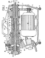
- a housing 1 which encloses all functional parts of the pipe cleaning machine and has the shape of a suitcase in outline.
- a carrying handle 2 is provided for transport purposes; two pairs of Rubber feet 3 and 4, of which the right pair 3 is fastened to a bracket 5 with elongated holes, not shown, in order, for example, to be able to compensate for the inclination of the machine on an inclined installation surface.
- Both hollow shafts consist of a hollow cylindrical part and a hollow cone 10 or 11, the hollow cones with their largest cross-sectional areas facing each other. Hollow shafts and hollow cones have identical axes of rotation.
- the hollow shaft 8 carries a toothed belt pulley 12 which is connected via a toothed belt 13 to a toothed belt pulley 14 which is seated on a drive shaft 15 of an electric motor 16 which can be switched with respect to its direction of rotation.
- the hollow cone 10 has an unspecified shoulder with which the hollow shaft 8 is supported on the bearing block 6 via a thrust bearing 17.
- the hollow shaft 9 is mounted only indirectly on the bearing block 7, specifically via a sliding sleeve 18 with a collar 19 which is guided in the bearing block 7 so as to be longitudinally displaceable but not rotatable.
- the longitudinal displacement takes place by means of an actuating lever 20 which is arranged on the side of the housing 1 and is fastened to a lever shaft 21.
- the lever shaft is connected to the collar 19 of the sliding sleeve 18 via two link plates 22 and 23 shown in dashed lines and corresponding link pins.
- the hollow cone 11 also has one Shoulder, not specified, with which the hollow shaft 9 is supported on the collar 19 via a thrust bearing 24.
- the coupling jaws 25 have conical surfaces at their two ends, which are essentially complementary to the conical surfaces of the hollow cones 10 and 11.
- the coupling jaws 25 were produced in such a way that an initially closed rotating body, which corresponds to the hatched representation, was divided into three sectors of equal size by axially parallel radial cuts. The cutting width was chosen so that the coupling jaws can later be moved radially inwards to such an extent that all cleaning spirals and collets for which the machine in question is designed can be detected.
- the coupling jaws 25 are held at a distance in the unloaded state by means of tangential compression springs 27 which are held in corresponding blind bores in the coupling jaws.
- the clutch shoes 25 are carried along by the driven hollow shaft 8 and in turn also drive the hollow shaft 9, so that slippage between the hollow cones and the clutch shoes does not occur.
- the lever 20 downward the hollow cone 11 is displaced to the right, as a result of which the clutch shoes 25 deflect radially inward due to the cone surfaces.
- these parts are taken along with a correspondingly increased pressure on the lever 20.
- the front end of the housing is designated 28.
- the part of a cleaning spiral 29 that is used for the cleaning process emerges from this end.
- the front end 28 faces the opening through which the cleaning spiral 29 is inserted into the pipeline to be cleaned.
- the housing has a connection coupling 31, parts of which belong to the housing 1, parts to a guide hose 32, which is a type of container for the end of the cleaning spiral 29 that is not in use.
- the part of the connecting coupling 31 belonging to the guide hose is referred to as the plug body 33, although it is understood that the connection can be made not only by a plug-in process, but also by a screwing process or a combined type of connection, such as a bayonet connection.
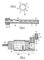
- connection coupling 31 Details of the connection coupling 31 are, however, explained in more detail below with reference to FIGS. 4 and 5. It should only be mentioned here that there is a cylindrical cavity 34 in the plug body 33, the axis of which coincides with the common axis AA of the entire system. In the cavity 34 there is a collet chuck 35 in which a collet 36 is rotatably mounted.
- Collet in the warehouse is made by circlips, not specified.
- an annular groove 37 is inserted into which a screw 38 engages radially, which has its counter thread in the plug body 33.
- the collet bearing 35 and thus the collet 36 is reliably fixed in the plug body 33.
- the collet 36 is coaxially aligned with the common axis A-A of the system. While details of the collet are explained in more detail with reference to FIGS. 2 and 3, FIG. 1 shows the relative position of the collet with respect to the rotary coupling 26.
- the rotary clutch 26 If, in the arrangement shown in FIG. 1, the rotary clutch 26 is actuated in the sense described above, the clutch jaws 25 first come into contact with the collet and take it along - initially by grinding - in the circumferential direction. The collet begins to rotate in the collet bearing 35. The part of the cleaning spiral 29 located within the collet has been omitted for the sake of clarity. When the rotary coupling 26 is actuated further, the collet 36 is then also pressed radially and in this case lies against the cleaning spiral 29, causing it to rotate.
- an index pin 40 is also arranged on the plug body 33, which engages in a corresponding housing bore (FIGS. 4 and 5). While the plug body 33 can be secured against rotation, in particular by the means according to FIG. 5, it is conceivable to provide the plug body according to FIG. 1 with a hollow cylindrical extension which is only shown in broken lines and engages in a corresponding cavity in the housing 1.
- the collet 36 is formed from a tube (seamlessly drawn precision steel tube) whose end remote from the collet bearing 35 is slit in the axial direction over a considerable length, namely three slots 41 distributed equidistantly on the circumference arranged.
- three fingers 42 are formed which can be moved radially inward under the action of the rotary clutch 26.
- the deformation that occurs here is only elastic because of the sufficient spring properties of the material.
- the end 43 of the slots 41 lies according to FIG. 1 at a location which is noticeably outside the clutch shoes 25, so that the rotary clutch cannot be blocked.
- the width of the slots 41 is so ge chooses that a sufficiently large inward movement of the fingers 42 is possible, in particular to be able to drive cleaning spirals 29 with different nominal diameters.
- the plug-in body 33 consists of a closed part 33a and a longitudinally divided part 33b.
- the longitudinally divided part 33b forms a type of clamp for clamping the guide tube 32.
- the index pin 40 is mounted in the axial extension 44a, specifically in a housing 45, which also encloses a compression spring (not designated in any more detail).
- the index pin 40 can be lifted upwards by a knurled disk 46. After lifting the index pin 40, it is possible to connect the plug body 33 to the housing 1 or to separate it again.
- a housing recess 47 is arranged which corresponds to the dimensions and position of the axial extension 44a.
- a bore 48 is made, which serves to engage the index pin 40.
- two rounded pins 49 are arranged, which serve to guide and hold the plug body 33.
Landscapes
- Engineering & Computer Science (AREA)
- Mechanical Engineering (AREA)
- Health & Medical Sciences (AREA)
- Life Sciences & Earth Sciences (AREA)
- Hydrology & Water Resources (AREA)
- Public Health (AREA)
- Water Supply & Treatment (AREA)
- Cleaning In General (AREA)
Applications Claiming Priority (2)
| Application Number | Priority Date | Filing Date | Title |
|---|---|---|---|
| DE19813109876 DE3109876A1 (de) | 1981-03-14 | 1981-03-14 | Rohrreinigungsmaschine mit einem behaelter fuer die aufnahme von reinigungsspiralen unterschiedlicher durchmesser |
| DE3109876 | 1981-03-14 |
Publications (2)
| Publication Number | Publication Date |
|---|---|
| EP0061003A1 true EP0061003A1 (fr) | 1982-09-29 |
| EP0061003B1 EP0061003B1 (fr) | 1984-12-27 |
Family
ID=6127266
Family Applications (1)
| Application Number | Title | Priority Date | Filing Date |
|---|---|---|---|
| EP82101331A Expired EP0061003B1 (fr) | 1981-03-14 | 1982-02-22 | Dispositif de nettoyage de tuyaux ayant un magasin pour spirales de dimensions différentes |
Country Status (4)
| Country | Link |
|---|---|
| US (1) | US4447926A (fr) |
| EP (1) | EP0061003B1 (fr) |
| AT (1) | ATE10911T1 (fr) |
| DE (2) | DE3109876A1 (fr) |
Cited By (3)
| Publication number | Priority date | Publication date | Assignee | Title |
|---|---|---|---|---|
| DE9400556U1 (de) * | 1994-01-14 | 1995-05-18 | Rothenberger Werkzeuge Masch | Rotationskupplung für den Antrieb von Reinigungsspiralen |
| DE4341075A1 (de) * | 1993-01-19 | 1995-06-08 | Rothenberger Werkzeuge Masch | Rohrreinigungsmaschine für den Antrieb eines flexiblen Reinigungselements |
| EP2704860A1 (fr) * | 2011-05-04 | 2014-03-12 | PCT Systems AB | Procédé pour devenir sûrement un conducteur habile dans l'utilisation d'un équipement de nettoyage de tuyaux interactif comprenant une machine qui possède un arbre flexible tournant dans une gaine fixe et machine pour la mise en uvre du procédé |
Families Citing this family (13)
| Publication number | Priority date | Publication date | Assignee | Title |
|---|---|---|---|---|
| DE3821667A1 (de) * | 1988-06-28 | 1990-01-18 | Rowo Rohr Und Kanal Reinigungs | Vorrichtung zum fuehren von rohrreinigungs-spiralen |
| US4914775A (en) * | 1988-12-19 | 1990-04-10 | Emerson Electric Co. | Retainer mechanism for drain cleaner drum |
| US5173984A (en) * | 1991-08-09 | 1992-12-29 | Lewisan Products, Inc. | Self-drying powered drain auger |
| DE19503276C1 (de) * | 1995-02-02 | 1996-04-25 | Rothenberger Werkzeuge Masch | Antriebsvorrichtung für die Federwelle einer Rohrreinigungsmaschine |
| US5657505A (en) * | 1996-01-29 | 1997-08-19 | Emerson Electric Company | Drain cleaning apparatus |
| US6009588A (en) | 1998-07-16 | 2000-01-04 | Emerson Electric Co. | Drain cleaning apparatus |
| DE19841813C2 (de) * | 1998-09-12 | 2001-03-22 | Rothenberger Werkzeuge Ag | Rohrreinigungsmaschine |
| US6076219A (en) * | 1999-01-15 | 2000-06-20 | Irwin; Lawrence F. | Waste line clean out apparatus |
| US6546582B2 (en) * | 2001-06-18 | 2003-04-15 | Lee H. Silverman | Drain cleaning machine and adjustable collet chuck mechanism therefor |
| DE10227204B4 (de) * | 2002-06-18 | 2005-01-05 | Rothenberger Ag | Verfahren zum Reinigen von Rohrleitungen und Rohrreinigungsmaschine hierfür |
| US11499593B2 (en) * | 2017-12-14 | 2022-11-15 | Ridge Tool Company | Tool-less clutch adjustment and removal for drain cleaner |
| CN114423533B (zh) | 2019-09-30 | 2024-01-23 | 米沃奇电动工具公司 | 排水管清洁机器的电机控制 |
| DE102020134885A1 (de) * | 2020-12-23 | 2022-06-23 | Antje Krausser | Vorrichtung und Verfahren zum Reinigen von Rohren |
Citations (1)
| Publication number | Priority date | Publication date | Assignee | Title |
|---|---|---|---|---|
| US2940099A (en) * | 1956-01-26 | 1960-06-14 | Karl J Kollmann | Sewer cleaner |
Family Cites Families (2)
| Publication number | Priority date | Publication date | Assignee | Title |
|---|---|---|---|---|
| US3213473A (en) * | 1963-09-03 | 1965-10-26 | Singer Louis | Pipe cleaning device |
| US4291429A (en) * | 1979-10-03 | 1981-09-29 | Robert Servadio | Drill attachment |
-
1981
- 1981-03-14 DE DE19813109876 patent/DE3109876A1/de not_active Withdrawn
-
1982
- 1982-02-22 AT AT82101331T patent/ATE10911T1/de not_active IP Right Cessation
- 1982-02-22 EP EP82101331A patent/EP0061003B1/fr not_active Expired
- 1982-02-22 DE DE8282101331T patent/DE3261658D1/de not_active Expired
- 1982-03-11 US US06/356,985 patent/US4447926A/en not_active Expired - Fee Related
Patent Citations (1)
| Publication number | Priority date | Publication date | Assignee | Title |
|---|---|---|---|---|
| US2940099A (en) * | 1956-01-26 | 1960-06-14 | Karl J Kollmann | Sewer cleaner |
Cited By (4)
| Publication number | Priority date | Publication date | Assignee | Title |
|---|---|---|---|---|
| DE4341075A1 (de) * | 1993-01-19 | 1995-06-08 | Rothenberger Werkzeuge Masch | Rohrreinigungsmaschine für den Antrieb eines flexiblen Reinigungselements |
| DE9400556U1 (de) * | 1994-01-14 | 1995-05-18 | Rothenberger Werkzeuge Masch | Rotationskupplung für den Antrieb von Reinigungsspiralen |
| EP2704860A1 (fr) * | 2011-05-04 | 2014-03-12 | PCT Systems AB | Procédé pour devenir sûrement un conducteur habile dans l'utilisation d'un équipement de nettoyage de tuyaux interactif comprenant une machine qui possède un arbre flexible tournant dans une gaine fixe et machine pour la mise en uvre du procédé |
| EP2704860A4 (fr) * | 2011-05-04 | 2015-04-22 | Pct Systems Ab | Procédé pour devenir sûrement un conducteur habile dans l'utilisation d'un équipement de nettoyage de tuyaux interactif comprenant une machine qui possède un arbre flexible tournant dans une gaine fixe et machine pour la mise en uvre du procédé |
Also Published As
| Publication number | Publication date |
|---|---|
| US4447926A (en) | 1984-05-15 |
| DE3109876A1 (de) | 1982-09-30 |
| ATE10911T1 (de) | 1985-01-15 |
| EP0061003B1 (fr) | 1984-12-27 |
| DE3261658D1 (en) | 1985-02-07 |
Similar Documents
| Publication | Publication Date | Title |
|---|---|---|
| EP0061003B1 (fr) | Dispositif de nettoyage de tuyaux ayant un magasin pour spirales de dimensions différentes | |
| DE7411789U (de) | Rohrreinigungsgeraet | |
| EP0588196B1 (fr) | Dispositif de travail destiné à être introduit dans une canalisation | |
| DE3714562A1 (de) | Werkzeugspindelanordnung mit einem elektrischen antriebsmotor | |
| EP2277634B1 (fr) | Appareil de nettoyage pour le nettoyage de conduits | |
| DE102008015532B4 (de) | Reinigungsgerät für die Reinigung von Rohrleitungen | |
| DE2617610A1 (de) | Kraftbetaetigtes drehmoment-werkzeug | |
| EP0029863B1 (fr) | Instrument à main dentaire | |
| DE10227204B4 (de) | Verfahren zum Reinigen von Rohrleitungen und Rohrreinigungsmaschine hierfür | |
| DE2714124C3 (de) | Vorrichtung zum losbaren Klemmen der Federwelle eines Rohrreinigungsgerates | |
| EP0724916B1 (fr) | Machine de nettoyage de tuyaux pour l'entraínement de spirales de nettoyage | |
| EP3181275B1 (fr) | Dispositif de changement rapide pour un outil | |
| DE202008018563U1 (de) | Reinigungsgerät für die Reinigung von Rohrleitungen | |
| CH621697A5 (fr) | ||
| DE1602825B2 (de) | Vorrichtung zur loesbaren befestigung eines spannfutters | |
| DE1652990B1 (de) | Einrichtung zum kontinuierlichen Wellen duennwandiger,insbesondere laengsnahtgeschweisster Glattrohre | |
| DE3545705A1 (de) | Handstueck fuer drehantreibbare werkzeuge | |
| DE2633223B2 (de) | Zahnärztliches Handstück | |
| DE3616731C2 (fr) | ||
| DE1817229B2 (de) | Gewindehämmereinrichtung | |
| DE19739359A1 (de) | Tragbare Rohrreinigungsmaschine | |
| DE19957990A1 (de) | Auszieheinrichtung für in Rollenwickelmaschinen eingesetzte Wickelrohre | |
| EP4257272A1 (fr) | Dispositif de guidage et de déviation d'une fraise-mère pour la production d'un trou de forage en contre-dépouille | |
| DE830346C (de) | Selbsttaetige Farbbandumkehrvorrichtung | |
| DE102022108066A1 (de) | Vorrichtung zur Führung und Auslenkung eines Bohrfräsers zur Herstellung eines hinterschnittenen Bohrlochs |
Legal Events
| Date | Code | Title | Description |
|---|---|---|---|
| PUAI | Public reference made under article 153(3) epc to a published international application that has entered the european phase |
Free format text: ORIGINAL CODE: 0009012 |
|
| AK | Designated contracting states |
Designated state(s): AT BE CH DE FR GB IT LU NL SE |
|
| 17P | Request for examination filed |
Effective date: 19830310 |
|
| ITF | It: translation for a ep patent filed |
Owner name: BARZANO' E ZANARDO MILANO S.P.A. |
|
| GRAA | (expected) grant |
Free format text: ORIGINAL CODE: 0009210 |
|
| AK | Designated contracting states |
Designated state(s): AT BE CH DE FR GB IT LI LU NL SE |
|
| REF | Corresponds to: |
Ref document number: 10911 Country of ref document: AT Date of ref document: 19850115 Kind code of ref document: T |
|
| REF | Corresponds to: |
Ref document number: 3261658 Country of ref document: DE Date of ref document: 19850207 |
|
| ET | Fr: translation filed | ||
| PG25 | Lapsed in a contracting state [announced via postgrant information from national office to epo] |
Ref country code: LU Free format text: LAPSE BECAUSE OF NON-PAYMENT OF DUE FEES Effective date: 19850228 |
|
| PLBE | No opposition filed within time limit |
Free format text: ORIGINAL CODE: 0009261 |
|
| STAA | Information on the status of an ep patent application or granted ep patent |
Free format text: STATUS: NO OPPOSITION FILED WITHIN TIME LIMIT |
|
| 26N | No opposition filed | ||
| PGFP | Annual fee paid to national office [announced via postgrant information from national office to epo] |
Ref country code: CH Payment date: 19910211 Year of fee payment: 10 Ref country code: AT Payment date: 19910211 Year of fee payment: 10 |
|
| PGFP | Annual fee paid to national office [announced via postgrant information from national office to epo] |
Ref country code: SE Payment date: 19910226 Year of fee payment: 10 |
|
| ITTA | It: last paid annual fee | ||
| PGFP | Annual fee paid to national office [announced via postgrant information from national office to epo] |
Ref country code: NL Payment date: 19910228 Year of fee payment: 10 |
|
| PG25 | Lapsed in a contracting state [announced via postgrant information from national office to epo] |
Ref country code: AT Effective date: 19920222 |
|
| PG25 | Lapsed in a contracting state [announced via postgrant information from national office to epo] |
Ref country code: SE Effective date: 19920223 |
|
| PG25 | Lapsed in a contracting state [announced via postgrant information from national office to epo] |
Ref country code: LI Effective date: 19920229 Ref country code: CH Effective date: 19920229 |
|
| PG25 | Lapsed in a contracting state [announced via postgrant information from national office to epo] |
Ref country code: NL Effective date: 19920901 |
|
| NLV4 | Nl: lapsed or anulled due to non-payment of the annual fee | ||
| REG | Reference to a national code |
Ref country code: CH Ref legal event code: PL |
|
| EUG | Se: european patent has lapsed |
Ref document number: 82101331.5 Effective date: 19920904 |
|
| PGFP | Annual fee paid to national office [announced via postgrant information from national office to epo] |
Ref country code: GB Payment date: 19970213 Year of fee payment: 16 |
|
| PGFP | Annual fee paid to national office [announced via postgrant information from national office to epo] |
Ref country code: FR Payment date: 19970214 Year of fee payment: 16 |
|
| PGFP | Annual fee paid to national office [announced via postgrant information from national office to epo] |
Ref country code: BE Payment date: 19970219 Year of fee payment: 16 |
|
| PGFP | Annual fee paid to national office [announced via postgrant information from national office to epo] |
Ref country code: DE Payment date: 19970226 Year of fee payment: 16 |
|
| PG25 | Lapsed in a contracting state [announced via postgrant information from national office to epo] |
Ref country code: GB Free format text: LAPSE BECAUSE OF NON-PAYMENT OF DUE FEES Effective date: 19980222 |
|
| PG25 | Lapsed in a contracting state [announced via postgrant information from national office to epo] |
Ref country code: FR Free format text: THE PATENT HAS BEEN ANNULLED BY A DECISION OF A NATIONAL AUTHORITY Effective date: 19980228 Ref country code: BE Free format text: LAPSE BECAUSE OF NON-PAYMENT OF DUE FEES Effective date: 19980228 |
|
| BERE | Be: lapsed |
Owner name: ROTHENBERGER G.M.B.H. & CO. WERKZEUGE-MASCHINEN K Effective date: 19980228 |
|
| GBPC | Gb: european patent ceased through non-payment of renewal fee |
Effective date: 19980222 |
|
| PG25 | Lapsed in a contracting state [announced via postgrant information from national office to epo] |
Ref country code: DE Free format text: LAPSE BECAUSE OF NON-PAYMENT OF DUE FEES Effective date: 19981103 |
|
| REG | Reference to a national code |
Ref country code: FR Ref legal event code: ST |