EP0061003A1 - Pipe-cleaning device with a container for cleaning "snakes" of different sizes - Google Patents
Pipe-cleaning device with a container for cleaning "snakes" of different sizes Download PDFInfo
- Publication number
- EP0061003A1 EP0061003A1 EP82101331A EP82101331A EP0061003A1 EP 0061003 A1 EP0061003 A1 EP 0061003A1 EP 82101331 A EP82101331 A EP 82101331A EP 82101331 A EP82101331 A EP 82101331A EP 0061003 A1 EP0061003 A1 EP 0061003A1
- Authority
- EP
- European Patent Office
- Prior art keywords
- cleaning
- coupling
- collet
- spiral
- spirals
- Prior art date
- Legal status (The legal status is an assumption and is not a legal conclusion. Google has not performed a legal analysis and makes no representation as to the accuracy of the status listed.)
- Granted
Links
Images

Classifications
-
- E—FIXED CONSTRUCTIONS
- E03—WATER SUPPLY; SEWERAGE
- E03F—SEWERS; CESSPOOLS
- E03F9/00—Arrangements or fixed installations methods or devices for cleaning or clearing sewer pipes, e.g. by flushing
- E03F9/002—Cleaning sewer pipes by mechanical means
- E03F9/005—Apparatus for simultaneously pushing and rotating a cleaning device carried by the leading end of a cable or an assembly of rods
-
- B—PERFORMING OPERATIONS; TRANSPORTING
- B08—CLEANING
- B08B—CLEANING IN GENERAL; PREVENTION OF FOULING IN GENERAL
- B08B9/00—Cleaning hollow articles by methods or apparatus specially adapted thereto
- B08B9/02—Cleaning pipes or tubes or systems of pipes or tubes
- B08B9/027—Cleaning the internal surfaces; Removal of blockages
- B08B9/04—Cleaning the internal surfaces; Removal of blockages using cleaning devices introduced into and moved along the pipes
- B08B9/043—Cleaning the internal surfaces; Removal of blockages using cleaning devices introduced into and moved along the pipes moved by externally powered mechanical linkage, e.g. pushed or drawn through the pipes
- B08B9/045—Cleaning the internal surfaces; Removal of blockages using cleaning devices introduced into and moved along the pipes moved by externally powered mechanical linkage, e.g. pushed or drawn through the pipes the cleaning devices being rotated while moved, e.g. flexible rotating shaft or "snake"
Definitions
- the invention relates to a pipe cleaning machine for driving cleaning spirals of different diameters, with a housing, a motor-driven hollow shaft with an inner diameter for the passage of the cleaning spiral, with a rotary clutch for taking the cleaning spiral, consisting of a set of clutch shoes that can be driven by the hollow shaft and can be moved into the projection of the inside diameter against the cleaning spiral, with a container for receiving the end of the cleaning spiral that is not in use, which can be aligned with the housing via a connecting coupling with the rotating coupling, and with one into the rotating coupling from the outside insertable, bridging differences in diameter rotatable collet.
- Such pipe cleaning machines are used to clean all possible sewage pipes and channels, which are often of considerable length and are provided with a large number of elbows, elbows, etc. It happens that the place of access to the pipeline is a considerable distance from the blockage point.
- the cleaning spirals which are not "real" spirals in the mathematical sense, but in principle coil springs, are therefore manufactured in finite partial lengths and can be extended using special couplings.
- the pipe cleaning machines for driving these cleaning spirals are usually designed in the form of suitcases or small trolleys, from which the end of the cleaning spiral which is not in use emerges at the rear. In the past, this end was rotated freely on the floor, often moving in a circle and starting to hit.
- adapter magazines are designed as rotatable drums and are aligned with the machine housing with the rotary coupling.
- the cleaning spiral is in operation pushed into (or pulled out) into the drum and winds up, helically in the drum, with the appropriate length even in several layers.
- This winding process does not always run smoothly even if the cleaning spiral has its original geometrically exact shape.
- there are larger or smaller loops or crooked turns in the drum so that a considerable unbalance is the result. Since the drum necessarily rotates at the spiral speed, the entire device begins to shake.
- the most common nominal diameters of the cleaning spirals today are 8, 10, 16 and 22 mm. Such different spiral diameters are required in order to meet the various cleaning requirements, the main ones are specified by the dimensioning and the course of the pipeline. Because of the large volume of cleaning spirals of large diameter wound in drums, for practical reasons it is not possible, for example, to provide a single drum for all four nominal diameters, the volume of which would then of course have to correspond to the cleaning spiral with the greatest length and the largest diameter. The procedure is therefore usually that drums of different diameters are used.
- the decisive value of a pipe cleaning machine is the inner diameter of the hollow shaft, which must be slightly larger than the outer diameter (nominal diameter) of the largest cleaning spiral used.
- the collets are triple-slotted tubes that are fixed to the drum and its brake cone are connected.
- the outer diameter corresponds to the 16 mm spiral
- the inner diameter corresponds on the one hand to the 8 mm spiral and on the other hand to the 10 mm spiral.
- two collets and two drums are required, which also have the above-mentioned shortcomings.
- a so-called guide hose is added to the known machine. This solution requires a wide range of accessories, which must be kept with the machine.
- the invention is therefore based on the object of specifying a pipe cleaning machine of the type described at the outset which manages with a minimum of accessories with regard to the containers for accommodating the cleaning spirals and with regard to the means for adapting to different spiral diameters.
- the object is achieved in that that the container for the cleaning spiral is designed in a manner known per se as a guide hose, that the inner diameter of the guide hose and the connecting coupling are equal to or larger than the inner diameter of the hollow shaft and that the collet for adapting the rotary coupling and the guide hose with connecting coupling to different spiral diameters is detachably mounted in the connection coupling.
- releasable is to be understood to mean any type of mounting or fastening which prevents unintentional displacement of the collet within the hollow shaft or the rotary coupling, but which allows the collet to be replaced without special tools or even exclusively by using force.
- This can happen, for example, in that the collet is held in the connection coupling in a form-fitting manner by means of a screw which can be tightened against the collet bearing.
- a screwdriver is sufficient to remove the collet with its bearing from the coupling.
- Such locking connections exist as so-called ball locks.
- a steel ball which can be displaced to a limited extent under the action of a spring, is pressed into a corresponding recess in the collet bearing. This effectively prevents undesired entrainment of the collet bearing; however, the collet can be removed together with the bearing by a tensile force from the coupling.
- the inner diameter of the hollow shaft is the decisive variable for the respective pipe cleaning machine.
- the measure of making both the inside diameter of the guide hose and that of the connecting coupling equal or larger than the inside diameter of the hollow shaft means that the guide hose can be used for all cleaning spirals for which the machine is designed (without the use of the collet) is. It is therefore sufficient to add a single guide hose for each machine type. Due to the easy detachability of the collet from the connection coupling, the guide hose can be used both with and without a collet.
- both the rotary coupling and the collet are designed to be compressible to at least two different nominal diameters of cleaning spirals due to the distances between the coupling jaws and the jaws in the unloaded state.
- a housing 1 which encloses all functional parts of the pipe cleaning machine and has the shape of a suitcase in outline.
- a carrying handle 2 is provided for transport purposes; two pairs of Rubber feet 3 and 4, of which the right pair 3 is fastened to a bracket 5 with elongated holes, not shown, in order, for example, to be able to compensate for the inclination of the machine on an inclined installation surface.
- Both hollow shafts consist of a hollow cylindrical part and a hollow cone 10 or 11, the hollow cones with their largest cross-sectional areas facing each other. Hollow shafts and hollow cones have identical axes of rotation.
- the hollow shaft 8 carries a toothed belt pulley 12 which is connected via a toothed belt 13 to a toothed belt pulley 14 which is seated on a drive shaft 15 of an electric motor 16 which can be switched with respect to its direction of rotation.
- the hollow cone 10 has an unspecified shoulder with which the hollow shaft 8 is supported on the bearing block 6 via a thrust bearing 17.
- the hollow shaft 9 is mounted only indirectly on the bearing block 7, specifically via a sliding sleeve 18 with a collar 19 which is guided in the bearing block 7 so as to be longitudinally displaceable but not rotatable.
- the longitudinal displacement takes place by means of an actuating lever 20 which is arranged on the side of the housing 1 and is fastened to a lever shaft 21.
- the lever shaft is connected to the collar 19 of the sliding sleeve 18 via two link plates 22 and 23 shown in dashed lines and corresponding link pins.
- the hollow cone 11 also has one Shoulder, not specified, with which the hollow shaft 9 is supported on the collar 19 via a thrust bearing 24.
- the coupling jaws 25 have conical surfaces at their two ends, which are essentially complementary to the conical surfaces of the hollow cones 10 and 11.
- the coupling jaws 25 were produced in such a way that an initially closed rotating body, which corresponds to the hatched representation, was divided into three sectors of equal size by axially parallel radial cuts. The cutting width was chosen so that the coupling jaws can later be moved radially inwards to such an extent that all cleaning spirals and collets for which the machine in question is designed can be detected.
- the coupling jaws 25 are held at a distance in the unloaded state by means of tangential compression springs 27 which are held in corresponding blind bores in the coupling jaws.
- the clutch shoes 25 are carried along by the driven hollow shaft 8 and in turn also drive the hollow shaft 9, so that slippage between the hollow cones and the clutch shoes does not occur.
- the lever 20 downward the hollow cone 11 is displaced to the right, as a result of which the clutch shoes 25 deflect radially inward due to the cone surfaces.
- these parts are taken along with a correspondingly increased pressure on the lever 20.
- the front end of the housing is designated 28.
- the part of a cleaning spiral 29 that is used for the cleaning process emerges from this end.
- the front end 28 faces the opening through which the cleaning spiral 29 is inserted into the pipeline to be cleaned.
- the housing has a connection coupling 31, parts of which belong to the housing 1, parts to a guide hose 32, which is a type of container for the end of the cleaning spiral 29 that is not in use.
- the part of the connecting coupling 31 belonging to the guide hose is referred to as the plug body 33, although it is understood that the connection can be made not only by a plug-in process, but also by a screwing process or a combined type of connection, such as a bayonet connection.
- connection coupling 31 Details of the connection coupling 31 are, however, explained in more detail below with reference to FIGS. 4 and 5. It should only be mentioned here that there is a cylindrical cavity 34 in the plug body 33, the axis of which coincides with the common axis AA of the entire system. In the cavity 34 there is a collet chuck 35 in which a collet 36 is rotatably mounted.
- Collet in the warehouse is made by circlips, not specified.
- an annular groove 37 is inserted into which a screw 38 engages radially, which has its counter thread in the plug body 33.
- the collet bearing 35 and thus the collet 36 is reliably fixed in the plug body 33.
- the collet 36 is coaxially aligned with the common axis A-A of the system. While details of the collet are explained in more detail with reference to FIGS. 2 and 3, FIG. 1 shows the relative position of the collet with respect to the rotary coupling 26.
- the rotary clutch 26 If, in the arrangement shown in FIG. 1, the rotary clutch 26 is actuated in the sense described above, the clutch jaws 25 first come into contact with the collet and take it along - initially by grinding - in the circumferential direction. The collet begins to rotate in the collet bearing 35. The part of the cleaning spiral 29 located within the collet has been omitted for the sake of clarity. When the rotary coupling 26 is actuated further, the collet 36 is then also pressed radially and in this case lies against the cleaning spiral 29, causing it to rotate.
- an index pin 40 is also arranged on the plug body 33, which engages in a corresponding housing bore (FIGS. 4 and 5). While the plug body 33 can be secured against rotation, in particular by the means according to FIG. 5, it is conceivable to provide the plug body according to FIG. 1 with a hollow cylindrical extension which is only shown in broken lines and engages in a corresponding cavity in the housing 1.
- the collet 36 is formed from a tube (seamlessly drawn precision steel tube) whose end remote from the collet bearing 35 is slit in the axial direction over a considerable length, namely three slots 41 distributed equidistantly on the circumference arranged.
- three fingers 42 are formed which can be moved radially inward under the action of the rotary clutch 26.
- the deformation that occurs here is only elastic because of the sufficient spring properties of the material.
- the end 43 of the slots 41 lies according to FIG. 1 at a location which is noticeably outside the clutch shoes 25, so that the rotary clutch cannot be blocked.
- the width of the slots 41 is so ge chooses that a sufficiently large inward movement of the fingers 42 is possible, in particular to be able to drive cleaning spirals 29 with different nominal diameters.
- the plug-in body 33 consists of a closed part 33a and a longitudinally divided part 33b.
- the longitudinally divided part 33b forms a type of clamp for clamping the guide tube 32.
- the index pin 40 is mounted in the axial extension 44a, specifically in a housing 45, which also encloses a compression spring (not designated in any more detail).
- the index pin 40 can be lifted upwards by a knurled disk 46. After lifting the index pin 40, it is possible to connect the plug body 33 to the housing 1 or to separate it again.
- a housing recess 47 is arranged which corresponds to the dimensions and position of the axial extension 44a.
- a bore 48 is made, which serves to engage the index pin 40.
- two rounded pins 49 are arranged, which serve to guide and hold the plug body 33.
Abstract
Description
Die Erfindung betrifft eine Rohrreinigungsmaschine für den Antrieb von Reinigungsspiralen unterschiedlicher Durchmesser, mit einem Gehäuse, einer motorisch angetriebenen Hohlwelle mit einem Innendurchmesser für die Hindurchführung der Reinigungsspirale, mit einer Rotationskupplung für die Mitnahme der Reinigungsspirale, bestehend aus einem Satz Kupplungsbacken, die von der Hohlwelle antreibbar und in die Projektion des Innendurchmessers gegen die Reinigungsspirale bewegbar sind, mit einem für die Aufnahme des nicht im Einsatz befindlichen Endes der Reinigungsspirale dienenden Behälter, der über eine Anschlußkupplung mit der Rotationskupplung fluchtend an das Gehäuse ansetzbar ist, sowie mit einer in die Rotationskupplung von außen einführbaren, Durchmesserunterschiede überbrückenden drehbaren Spannzange.The invention relates to a pipe cleaning machine for driving cleaning spirals of different diameters, with a housing, a motor-driven hollow shaft with an inner diameter for the passage of the cleaning spiral, with a rotary clutch for taking the cleaning spiral, consisting of a set of clutch shoes that can be driven by the hollow shaft and can be moved into the projection of the inside diameter against the cleaning spiral, with a container for receiving the end of the cleaning spiral that is not in use, which can be aligned with the housing via a connecting coupling with the rotating coupling, and with one into the rotating coupling from the outside insertable, bridging differences in diameter rotatable collet.
Derartige Rohrreinigungsmaschinen dienen zur Reinigung aller möglichen Abwasserrohre und -kanäle, die häufig eine beträchtliche Länge aufweisen und mit einer Vielzahl von Krümmern, Winkelstücken etc. versehen sind. Dabei kommt es vor, daß der Ort des Zugangs zur Rohrleitung eine beträchtliche Entfernung von der Verstopfungsstelle hat. Die Reinigungsspiralen, die keine "echten" Spiralen im mathematischen Sinne, sondern im Prinzip Schraubenfedern sind, werden daher in endlichen Teillängen gefertigt und sind durch spezielle Kupplungen verlängerbar. Die Rohrreinigungsmaschinen zum Antrieb dieser Reinigungsspiralen sind meist in Form von Koffern oder kleinen Wagen ausgebildet, aus denen das nicht im Einsatz befindliche Ende der Reinigungsspirale hinten heraustritt. Früher ließ man dieses Ende frei auf dem Boden rotieren, wobei es sich häufig in einem Kreis bewegte und zu schlagen begann. Hierbei ist zu berücksichtigen, daß die Drehzahlen bis zu 600 U/min betragen, um beispielsweise Kettenschleudern und Fräser zum Einsatz bringen zu können. Durch das Abwälzen und Schlagen des freien Endes der Reinigungsspirale haben sich Unfälle ereignet, so daß mittlerweile Sicherheitsvorschriften bestehen, die die Unterbringung der Reinigungsspirale in einem Behälter vorschreiben.Such pipe cleaning machines are used to clean all possible sewage pipes and channels, which are often of considerable length and are provided with a large number of elbows, elbows, etc. It happens that the place of access to the pipeline is a considerable distance from the blockage point. The cleaning spirals, which are not "real" spirals in the mathematical sense, but in principle coil springs, are therefore manufactured in finite partial lengths and can be extended using special couplings. The pipe cleaning machines for driving these cleaning spirals are usually designed in the form of suitcases or small trolleys, from which the end of the cleaning spiral which is not in use emerges at the rear. In the past, this end was rotated freely on the floor, often moving in a circle and starting to hit. It must be taken into account here that the speeds are up to 600 rpm, in order to be able to use chain spinners and milling cutters, for example. Accidents have occurred due to the rolling and beating of the free end of the cleaning spiral, so that safety regulations now exist which stipulate that the cleaning spiral be accommodated in a container.
Es ist beispielsweise bekannt, als Behälter sogenannte Adaptermagazine zu verwenden, die als drehbare Trommeln ausgefUhrt sind und mit der Rotationskupplung fluchtend an das Maschinengehäuse angesetzt werden. Die Reinigungsspirale wird beim Betrieb in die Trommel hineingeschoben (oder herausgezogen) und wickelt, sich in der Trommel schraubenlinienförmig auf, bei entsprechender Länge sogar in mehreren Lagen. Dieser Aufwickelvorgang verläuft selbst dann nicht immer einwandfrei, wenn die Reinigungsspirale ihre ursprüngliche geometrisch exakte Form besitzt. Es kommt gelegentlich zu größeren oder kleineren Schlingen oder schief stehenden Windungen in der Trommel, so daß eine erhebliche Unwucht die Folge ist. Da die Trommel notwendigerweise mit der Spiralendrehzahl rotiert, fängt die gesamte Vorrichtung an zu rütteln.For example, it is known to use so-called adapter magazines as containers, which are designed as rotatable drums and are aligned with the machine housing with the rotary coupling. The cleaning spiral is in operation pushed into (or pulled out) into the drum and winds up, helically in the drum, with the appropriate length even in several layers. This winding process does not always run smoothly even if the cleaning spiral has its original geometrically exact shape. Occasionally there are larger or smaller loops or crooked turns in the drum, so that a considerable unbalance is the result. Since the drum necessarily rotates at the spiral speed, the entire device begins to shake.
Hinzu kommt, daß bei einer ganz oder teilweise gefüllten Trommel ein erhebliches Trägheitsmoment gebildet wird, so daß die Trommel beim Ublichen absatzweisen Betrieb der Maschine abgebremst werden muß. Ansonsten würde nämlich die Spirale auch nach dem Auskuppeln zunächst mit der Trommeldrehzahl weiter rotieren, bis die Energie der rotierenden Masse aufgebraucht ist. Dies kann bei einer hartnäckigen Verstopfung zu einer Zerstörung der Spirale oder des auf die Spirale aufgesetzten Reinigungswerkzeugs fUhren. In der Regel sind daher die bekannten Trommeln mit einer Bremse, meist einer Konusbremse, ausgestattet, deren Betätigung über einen im Maschinengehäuse vorhandenen Mechanismus, meist den in entgegengesetzter Richtung betätigten Kupplungshebel, erfolgt.In addition, a considerable moment of inertia is formed in a fully or partially filled drum, so that the drum must be braked during normal operation of the machine. Otherwise, even after disengagement, the spiral would initially continue to rotate at the drum speed until the energy of the rotating mass has been used up. If the blockage is persistent, this can destroy the spiral or the cleaning tool attached to the spiral. As a rule, the known drums are therefore equipped with a brake, usually a conical brake, which is actuated via a mechanism in the machine housing, usually the clutch lever actuated in the opposite direction.
Die heute gebräuchlichsten Nenndurchmesser der Reinigungsspiralen betragen 8, 10, 16 und 22 mm. Man benötigt derart unterschiedliche Spiralendurchmesser, um den verschiedenen Reinigungsanforderungen gerecht zu werden, die hauptsächlich durch die Dimensionierung und den Verlauf der Rohrleitung vorgegeben sind. Wegen des großen Volumens von in Trommeln aufgewickelten Reinigungsspiralen großen Durchmessers ist es aus praktischen GrUnden nicht möglich,beispielsweise fUr alle vier Nenndurchmesser eine einzige Trommel vorzusehen , deren Volumen dann natUrlich der Reinigungsspirale mit der größten Länge und dem größten Durchmesser entsprechen müßte. Man verfährt daher in der Regel so, daß man Trommeln unterschiedlichen Durchmessers verwendet.The most common nominal diameters of the cleaning spirals today are 8, 10, 16 and 22 mm. Such different spiral diameters are required in order to meet the various cleaning requirements, the main ones are specified by the dimensioning and the course of the pipeline. Because of the large volume of cleaning spirals of large diameter wound in drums, for practical reasons it is not possible, for example, to provide a single drum for all four nominal diameters, the volume of which would then of course have to correspond to the cleaning spiral with the greatest length and the largest diameter. The procedure is therefore usually that drums of different diameters are used.
Reinigungsspiralen mit den oben genannten, zwischen 8 und 22 mm liegenden Nenndurchmessern, können im allgemeinen ohne besondere Maßnahmen nicht durch die gleiche Rotationskupplung angetrieben werden, da die bekannte Geometrie der Kupplungsbacken ein derartiges Feld nicht überbrückt. Man kann aber ohne weiteres mit der gleichen Rotationskupplung 16-mm- und 22-mm-Spiralen antreiben. Desgleichen ist es wiederum möglich, mit einer anders dimensionierten Rotationskupplung 8-mm- und 10-mm-Spiralen anzutreiben.Cleaning spirals with the above-mentioned nominal diameters between 8 and 22 mm cannot generally be driven by the same rotary clutch without special measures, since the known geometry of the clutch shoes does not bridge such a field. But you can easily drive 16 mm and 22 mm spirals with the same rotary coupling. Likewise, it is again possible to drive 8 mm and 10 mm spirals with a differently dimensioned rotary coupling.
Der maßgebende Wert einer Rohrreinigungsmaschine ist der Innendurchmesser der Hohlwelle, der geringfügig größer sein muß als der Außendurchmesser (Nenndurchmesser) der größten zum Einsatz kommenden Reinigungsspirale. Um eine Maschine für 16-mm-Spiralen auch für 8-mm- und 10-mm-Spiralen verwenden zu können, ist es bekannt, einer solchen Maschine zwei Trommeln beizugeben, die mit sogenannten Spannzangen ausgestattet sind. Bei den Spannzangen handelt es sichum dreifach geschlitzte Rohre, die fest mit der Trommel und deren Bremskonus verbunden sind. Der Außendurchmesser entspricht dabei der 16-mm-Spirale, während der Innendurchmesser einerseits der 8-mm-Spirale und andererseits der 10-mm-Spirale entspricht. Es werden also in jedem Falle zwei Spannzangen und zwei Trommeln benötigt, die zudem noch mit den oben angegebenen Unzulänglichkeiten behaftet sind. Für die 16-mm-Spirale wird der bekannten Maschine ein sogenannter FUhrungsschlauch beigegeben. Diese Lösung bedingt ein umfangreiches Zubehör, welches laufend mit der Maschine mitgeführt werden muß.The decisive value of a pipe cleaning machine is the inner diameter of the hollow shaft, which must be slightly larger than the outer diameter (nominal diameter) of the largest cleaning spiral used. In order to be able to use a machine for 16 mm spirals for 8 mm and 10 mm spirals, it is known to add two drums to such a machine, which are equipped with so-called collets. The collets are triple-slotted tubes that are fixed to the drum and its brake cone are connected. The outer diameter corresponds to the 16 mm spiral, while the inner diameter corresponds on the one hand to the 8 mm spiral and on the other hand to the 10 mm spiral. In any case, two collets and two drums are required, which also have the above-mentioned shortcomings. For the 16 mm spiral, a so-called guide hose is added to the known machine. This solution requires a wide range of accessories, which must be kept with the machine.
Es ist weiterhin bekannt, eine Spannzange, die gleichzeitig für 8-mm- und 10-mm-Spiralen verwendbar ist, insoweit fest mit einem Führungsschlauch zu verbinden, daß die Spannzange gegenüber dem Führungsschlauch zwar drehbar, nicht aber ohne weiteres ausbaubar ist. Außerdem gestattet der Führungsschlauch nur die Aufnahme von Spiralen mit maximal 10 mm Nenndurchmesser, so daß für größere Spiralendurchmesser ein weiterer FUhrungsschlauch - ohne Spannzange - vorhanden sein muß. Die beiden Führungsschläuche haben zusammen einen Platzbedarf, der den der Maschine beträchtlich Ubersteigt.It is also known to connect a collet, which can be used simultaneously for 8 mm and 10 mm spirals, to the extent that the collet is rotatable relative to the guide hose, but cannot be removed easily. In addition, the guide hose only allows the inclusion of spirals with a maximum nominal diameter of 10 mm, so that for larger spiral diameters an additional guide hose - without a collet - must be available. The two guide hoses together have a space requirement that considerably exceeds that of the machine.
Der Erfindung liegt daher die Aufgabe zugrunde, eine Rohrreinigungsmaschine der eingangs beschriebenen Art anzugeben, die bezüglich der Behälter für die Aufnahme der Reinigungsspiralen und bezüglich der Mittel für die Anpassung an unterschiedliche Spiralendurchmesser mit einem Minimum an Zubehör auskommt.The invention is therefore based on the object of specifying a pipe cleaning machine of the type described at the outset which manages with a minimum of accessories with regard to the containers for accommodating the cleaning spirals and with regard to the means for adapting to different spiral diameters.
Die Lösung der gestellten Aufgabe erfolgt bei der eingangs beschriebenen Rohrreinigungsmaschine erfindungsgemäß dadurch, daß der Behälter für die Reinigungsspirale in an sich bekannter Weise als FUhrungsschlauch ausgebildet ist, daß die Innendurchmesser des FUhrungsschlauches und der Anschlußkupplung gleich oder größer sind als der Innendurchmesser der Hohlwelle und daß die Spannzange für die Anpassung der Rotationskupplung und des FUhrungsschlauchs mit Anschlußkupplung an unterschiedliche Spiralendurchmesser lösbar in der Anschlußkupplung gelagert ist.In the pipe cleaning machine described at the outset, the object is achieved in that that the container for the cleaning spiral is designed in a manner known per se as a guide hose, that the inner diameter of the guide hose and the connecting coupling are equal to or larger than the inner diameter of the hollow shaft and that the collet for adapting the rotary coupling and the guide hose with connecting coupling to different spiral diameters is detachably mounted in the connection coupling.
Unter lösbar soll im vorstehenden Zusammenhang jede Art der Lagerung bzw. Befestigung verstanden werden, die ein unbeabsichtigtes Verschieben der Spannzange innerhalb der Hohlwelle bzw. der Rotationskupplung verhindert, aber ohne Spezialwerkzeuge oder sogar ausschließlich durch Kraftanwendung ein Auswechseln der Spannzange erlaubt. Dies kann beispielsweise dadurch geschehen, daß die Spannzange formschlUssig mittels einer gegen das Spannzangenlager festziehbaren Schraube in der Anschlußkupplung gehalten ist. In diesem Falle genügt ein Schraubenzieher, um die Spannzange mit ihrem Lager aus der Anschlußkupplung entnehmen zu können. Es ist aber ohne weiteres auch möglich, das Spannzangenlager mittels einer Rastverbindung in die Anschlußkupplung einzusetzen. Derartige Rastverbindungen gibt es als sogenannte Kugelrastungen. Hierbei wird eine Stahlkugel, die unter der Wirkung einer Feder begrenzt verschiebbar ist, in eine entsprechende Ausnehmung im Spannzangenlager gedrückt. Eine unerwünschte Mitnahme des Spannzangenlagers wird dadurch wirksam verhindert; die Spannzange läßt sich jedoch zusammen mit dem Lager durch eine Zugkraft aus der Anschlußkupplung entnehmen.In the above context, releasable is to be understood to mean any type of mounting or fastening which prevents unintentional displacement of the collet within the hollow shaft or the rotary coupling, but which allows the collet to be replaced without special tools or even exclusively by using force. This can happen, for example, in that the collet is held in the connection coupling in a form-fitting manner by means of a screw which can be tightened against the collet bearing. In this case, a screwdriver is sufficient to remove the collet with its bearing from the coupling. However, it is also easily possible to insert the collet bearing into the connection coupling by means of a snap connection. Such locking connections exist as so-called ball locks. Here, a steel ball, which can be displaced to a limited extent under the action of a spring, is pressed into a corresponding recess in the collet bearing. This effectively prevents undesired entrainment of the collet bearing; however, the collet can be removed together with the bearing by a tensile force from the coupling.
Es wurde bereits weiter oben ausgeführt, daß der Innendurchmesser der Hohlwelle die maßgebende Größe für die jeweilige Rohrreinigungsmaschine ist. Durch die Maßnahme, sowohl den Innendurchmesser des Führungsschlauchs als auch den der Anschlußkupplung gleich oder größer zu machen als den Innendurchmesser der Hohlwelle wird somit erreicht, daß der FUhrungsschlauch für sämtliche Reinigungsspiralen verwendet werden kann, für die auch die Maschine (ohne Einsatz der Spannzange) ausgelegt ist. Es genügt infolgedessen für jede Maschinentype die Beigabe eines einzigen Führungsschlauchs. Durch die leichte Lösbarkeit der Spannzange aus der Anschlußkupplung läßt sich der FUhrungsschlauch sowohl mit als auch ohne Spannzange verwenden.It has already been stated above that the inner diameter of the hollow shaft is the decisive variable for the respective pipe cleaning machine. The measure of making both the inside diameter of the guide hose and that of the connecting coupling equal or larger than the inside diameter of the hollow shaft means that the guide hose can be used for all cleaning spirals for which the machine is designed (without the use of the collet) is. It is therefore sufficient to add a single guide hose for each machine type. Due to the easy detachability of the collet from the connection coupling, the guide hose can be used both with and without a collet.
Es ist dabei gemäß der weiteren Erfindung besonders vorteilhaft, wenn sowohl die Rotationskupplung als auch die Spannzange aufgrund der Abstände der Kupplungsbacken bzw. der Zangenbacken in entlastetem Zustand auf mindestens zwei unterschiedliche Nenndurchmesser von Reinigungsspiralen zusammendrUckbar ausgebildet sind.According to the further invention, it is particularly advantageous if both the rotary coupling and the collet are designed to be compressible to at least two different nominal diameters of cleaning spirals due to the distances between the coupling jaws and the jaws in the unloaded state.
Durch die Kombination dieser Maßnahmen wird beispielsweise erreicht, daß der gleiche FUhrungsschlauch - ohne Spannzange - sowohl für 22-mm- als auch für 16-mm-Spiralen verwendet werden kann, und daß wiederum der gleiche Führungsschlauch - mit Spannzange - sowohl für 10-mm- als auch für 8-mm-Spiralen verwendet werden kann. Eine einzige Rohrreinigungsmaschine in Verbindung mit einem einzigen Führungsschlauch kann infolgedessen bei entsprechender Dimensionierung der Hohlwelle für insgesamt vier verschiedene Spiralendurchmesser verwendet werden, ohne daß weiteres Zubehör benötigt wird.The combination of these measures ensures, for example, that the same guide hose - without collet - can be used for both 22 mm and 16 mm spirals, and that the same guide hose - with collet - can be used for both 10 mm - Can also be used for 8 mm spirals. A single pipe cleaning machine in connection with a single guide hose can consequently be used for a total of four different spiral diameters without dimensioning the hollow shaft accordingly that additional accessories are needed.
Ein AusfUhrungsbeispiel des Erfindungsgegenstandes wird nachfolgend anhand der Figuren 1 bis 5 näher erläutert.An exemplary embodiment of the subject matter of the invention is explained in more detail below with reference to FIGS. 1 to 5.
Es zeigen:
Figur 1 einen teilweisen Vertikalschnitt durch eine vollständige Rohrreinigungsmaschine,- Figur 2 einen Längsschnitt durch die Spannzange mit Spannzangenlager,
- Figur 3 eine Draufsicht auf die Stirnseite des geschlitzten Endes der Spannzange nach Figur 2,
Figur 4 teilweise im Schnitt, teilweise in der Seitenansicht das mit dem FUhrungsschlauch verbundene Teil der Anschlußkupplung undFigur 5 eine Draufsicht auf das hintere Ende der Maschine mit dem gehäuseseitigen Teil der Anschlußkupplung sowie - teilweise geschnitten - auf das mit dem FUhrungsschlauch verbundene Teil der Anschlußkupplung.
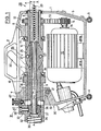
- FIG. 1 shows a partial vertical section through a complete pipe cleaning machine,
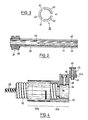
- FIG. 2 shows a longitudinal section through the collet with collet bearings,
- FIG. 3 shows a top view of the end face of the slotted end of the collet according to FIG. 2,
- Figure 4 partly in section, partly in side view, the part of the connecting coupling connected to the guide hose and
- Figure 5 is a plan view of the rear end of the machine with the housing-side part of the connection coupling and - partially cut - on the part of the connection coupling connected to the guide hose.
In Figur 1 ist ein Gehäuse 1 gezeigt, welches sämtliche Funktionsteile der Rohrreinigungsmaschine umschließt und im Umriß etwa die Form eines Koffers hat. Zu Transportzwecken ist ein Traggriff 2 vorgesehen; zum Abstellen dienen zwei Paare von Gummifüssen 3 und 4, von denen das rechte Paar 3 an einer Lasche 5 mit nicht gezeigten Langlöchern befestigt ist, um beispielsweise die Neigung der Maschine auf einer schiefen Aufstellfläche ausgleichen zu können.In Figure 1, a
Mit dem Gehäuse 1 aus einem Stück bestehen zwei Lagerböcke 6 und 7, in denen zwei Hohlwellen 8 und 9 gelagert sind. Beide Hohlwellen bestehen aus einem hohlzylindrischen Teil und je einem Hohlkegel 10 bzw. 11, wobei die Hohlkegel mit ihren größten Querschnittsflächen aufeinander zugerichtet sind. Hohlwellen und Hohlkegel haben identische Rotationsachsen. Die Hohlwelle 8 trägt eine Zahnriemenscheibe 12, die über einen Zahnriemen 13 mit einer Zahmriemenscheibe 14 verbunden ist, die auf einer Antriebswelle 15 eines Elektromotors 16 sitzt, der hinsichtlich seiner Drehrichtung umschaltbar ist. Der Hohlkegel 10 besitzt eine nicht näher bezeichnete Schulter, mit der sich die Hohlwelle 8 über ein Drucklager 17 am Lagerbock 6 abstützt.With the
Die Hohlwelle 9 ist nur mittelbar irm Lagerbock 7 gelagert, und zwar über eine Schiebehülse 18 mit einem Bund 19, die im Lagerbock 7 zwar längsverschiebbar, aber nicht verdrehbar geführt ist. Die Längsverschiebung erfolgt mittels eines Betätigungshebels 20, der seitlich vom Gehäuse 1 angeordnet und an einer Hebelwelle 21 befestigt ist. Die Hebelwelle ist über zwei gestrichelt dargestellte Gelenklaschen 22 und 23 und entsprechende Gelenkbolzen mit dem Bund 19 der Schiebehülse 18 verbunden. Durch einen Druck auf den Betätigungshebel 20 nach unten ist es auf diese Weise möglich, die Schiebehülse 18 nach rechts zu bewegen. Der Hohlkegel 11 besitzt gleichfalls eine nicht näher bezeichnete Schulter, mit der sich die Hohlwelle 9 Uber ein Drucklager 24 an dem Bund 19 abstützt. Obwohl mit Ausnahme der Drucklager 17 und 24 alle andern Lagerstellen als Gleitlager gezeichnet sind, versteht es sich, daß die betreffenden Lager als Wälzlager ausgeführt sein können und bevorzugt als Nadellager ausgeführt sind.The hollow shaft 9 is mounted only indirectly on the
Zwischen den Hohlkegeln 10 und 11 befinden sich, teilweise in diese hineinragend, drei auf den Umfang verteilte Kupplungsbacken 25, die zusammen mit den Hohl kegeln 10 und 11 eine Rotationskupplung 26 bilden. Die Kupplungsbacken 25 besitzen an ihren beiden Enden Kegelflächen, die zu den Kegelflächen der Hohlkegel 10 und 11 im wesentlichen komplementär sind. Die Kupplungsbacken 25 wurden in der Weise hergestellt, daß ein zunächst geschlossener Rotationskörper, welcher der schraffierten Darstellung entspricht, durch achsparallele Radialschnitte in drei gleich große Sektoren zerlegt wurde. Dabei wurde die Schnittbreite so gewählt, daß sich die Kupplungsbacken später um ein solches Maß radial einwärts bewegen lassen, daß sämtliche Reinigungsspiralen und Spannzangen erfaßt werden können, für die die betreffende Maschine ausgelegt ist. Die Kupplungsbacken 25 werden mittels tangentialer Druckfedern 27, die in entsprechenden Sackbohrungen in den Kupplungsbacken gehalten sind, in unbelastetem Zustand auf Distanz gehalten.Between the
Beim Betrieb der Maschine und zunächst nicht betätigtem Hebel 20 werden die Kupplungsbacken 25 von der angetriebenen Hohlwelle 8 mitgenommen und treiben ihrerseits auch die Hohlwelle 9 an, so daß ein Schlupf zwischen den Hohlkegeln und den Kupplungsbacken nicht auftritt. Durch eine Abwärtsbewegung des Hebels 20 wird der Hohlkegel 11 nach rechts verschoben, wodurch die Kupplungsbacken 25 aufgrund der Kegelflächen radial einwärts ausweichen. Sobald sie hierbei auf einen entsprechenden Rotationskörper, sei es eine Reinigungsspirale, sei es eine Spannzange, auftreffen, werden diese Teile bei entsprechend verstärktem Druck auf den Hebel 20 mitgenommen.When the machine is in operation and the
Das vordere Ende des Gehäuse ist mit 28 bezeichnet. Aus diesem Ende tritt derjenige Teil einer Reinigungsspirale 29 aus, der für den Reinigungsvorgang benutzt wird. Das vordere Ende 28 ist dabei der öffnung zugekehrt, durch die die Reinigungsspirale 29 in die zu reinigende Rohrleitung eingeführt wird. Am hinteren Ende 30 besitzt das Gehäuse eine Anschlußkupplung 31, von der Teile zum Gehäuse 1, Teile zu einem FUhrungsschlauch 32 gehören, der eine Art Behälter für das nicht im Einsatz befindliche Ende der Reinigungsspirale 29 darstellt. Der zum FUhrungsschlauch gehörende Teil der Anschlußkupplung 31 wird als Steckkörper 33 bezeichnet, obwohl es sich versteht, daß die Verbindung nicht nur durch einen Steckvorgang, sondern auch durch einen Schraubvorgang oder eine kombinierte Verbindungsart erfolgen kann wie beispielsweise durch eine Bajonettverbindung. Einzelheiten der Anschlußkupplung 31 werden jedoch weiter unten anhand der Figuren 4 und 5 näher erläutert. Hier sei nur so viel erwähnt, daß sich im Steckkörper 33 ein zylindrischer Hohlraum 34 befindet, dessen Achse mit der gemeinsamen Achse A-A des gesamten Systems zusammenfällt. Im Hohlraum 34 befindet sich ein Spannzangenlager 35, in dem drehbar eine Spannzange 36 gelagert ist. Die axiale Festlegung derThe front end of the housing is designated 28. The part of a
Spannzange im Lager erfolgt durch nicht näher bezeichnete Sicherungsringe. Im Spannzangenlager 35 ist eine Ringnut 37 eingestochen, in die radial eine Schraube 38 eingreift, die ihr Gegengewinde im Steckkörper 33 hat. Auf diese Weise ist das Spannzangenlager 35 und damit die Spannzange 36 zuverlässig im Steckkörper 33 festgelegt. Insbesondere ist die Spannzange 36 mit Bezug auf die gemeinsame Achse A-A des Systems koaxial ausgerichet. Während Einzelheiten der Spannzange anhand der Figuren 2 und 3 näher erläutert werden, zeigt Figur 1 die relative Lage der Spannzange zur Rotationskupplung 26.Collet in the warehouse is made by circlips, not specified. In the
Wird bei der in Figur 1 dargestellten Anordnung die Rotationskupplung 26 in dem weiter oben beschriebenen Sinne betätigt, so kommen die Kupplungsbacken 25 zunächst mit der Spannzange in BerUhrung und nehmen diese - zunächst schleifend - in Umfangsrichtung mit. Dabei beginnt sich die Spannzange im Spannzangenlager 35 zu drehen. Der innerhalb der Spannzange liegende Teil der Reinigungsspirale 29 wurde der übersichtlichkeit halber fortgelassen. Bei weiterer Betätigung der Rotationskupplung 26 wird als-dann auch die Spannzange 36 radial zusammengedrUckt und legt sich hierbei an die Reinigungsspirale 29 an, diese in Rotation versetzend. Es ist erkennbar, daß nach dem Ausbau der Spannzange durch einfaches Lösen der Schraube 38 anstelle der gezeigten kleinen Reinigungsspirale 29 auch eine solche Spirale in das System eingeführt werden kann, die bis an die Zylinderflächen der Hohlwellen heranreicht. Es wurde bereits weiter oben ausgeführt, daß das bestimmende Merkmal der Innendurchmesser der Hohlwelle bzw. der Hohlwellen 8 und 9 ist, der in Figur 1 mit "D" angegeben ist. Nach dem Ausbau der Spannzange 36 kann jede Reinigungsspirale in das System eingesetzt werden, deren Außendurchmesser das Maß "D" ausreichend unterschreitet. Es versteht sich, daß der Innendurchmesser des Führungsschlauchs 32 den erfindungsgemäßen Bedingungen entspricht, und daß auch eine Bohrung 39 im Steckkörper 33, die eine Schulter für den Anschlag des Führungsschlauches 32 begrenzt, den erfindungsgemäßen Bedingungen genügt.If, in the arrangement shown in FIG. 1, the rotary clutch 26 is actuated in the sense described above, the
Zur Festlegung des Steckkörpers 33 gegenüber dem Gehäuse 1 ist am Steckkörper 33 noch ein Indexstift 40 angeordnet, der in eine entsprechende Gehäusebohrung eingreift (Figuren 4 und 5). Während eine verdrehsichere Befestigung des Steckkörpers 33 insbesondere durch die Mittel gemäß Figur 5 herbeigeführt werden kann, ist es denkbar, den Steckkörper gemäß Figur 1 mit einem hohlzylindrischen Fortsatz zu versehen, der nur gestrichelt dargestellt ist und in einen entsprechenden Hohlraum im Gehäuse 1 eingreift.To fix the
Aus den Figuren 2 und 3 ist ersichtlich, daß die Spannzange 36 aus einem Rohr (nahtlos gezogenes Präzisionsstahlrohr) gebildet ist, deren vom Spannzangenlager 35 abgekehrtes Ende auf einer beträchtlichen Länge in Achsrichtung geschlitzt ist, und zwar sind auf dem Umfang äquidistant verteilt drei Schlitze 41 angeordnet. Hierdurch werden drei Finger 42 gebildet, die unter der Wirkung der Rotationskupplung 26 radial einwärts bewegt werden können. Die hierbei erfolgende Verformung ist lediglich elastisch aufgrund ausreichender Federeigenschaften des Werkstoffs. Das Ende 43 der Schlitze 41 liegt dabei gemäß Figur 1 an einer Stelle, die merklich außerhalb der Kupplungsbacken 25 liegt, so daß keine Blockierung der Rotationskupplung eintreten kann. Die Breite der Schlitze 41 ist dabei so gewählt, daß eine genügend große Einwärtsbewegung der Finger 42 möglich ist, um insbesondere auch Reinigungsspiralen 29 mit unterschiedlichen Nenndurchmessern antreiben zu können.It can be seen from FIGS. 2 and 3 that the
Den Figuren 4 und 5 ist noch zu entnehmen, daß der Steckkörper 33 aus einem geschlossenen Teil 33a und einem längsgeteilten Teil 33b besteht. Der längsgeteilte Teil 33b bildet eine Art Schelle für die Klemmung des Führungsschlauches 32. An dem geschlossenen Teil 33a befindet sich in Richtung auf das Gehäuse 1 (Figur 1) ein Ausleger 44, der radial und axial gegenüber dem Steckkörper vorspringt. In dem axialen Fortsatz 44a ist der Indexstift 40 gelagert, und zwar in einem Gehäuse 45, welches auch eine nicht näher bezeichnete Druckfeder umschließt. Der Indexstift 40 kann nach oben durch eine Rändelscheibe 46 angehoben werden. Nach Anheben des Indexstiftes 40 ist es möglich, den Steckkörper 33 mit dem Gehäuse 1 zu verbinden oder wieder von diesem zu trennen.It can also be seen from FIGS. 4 and 5 that the plug-in
Aus Figur 5 ist noch zu entnehmen, daß am hinteren Ende des Gehäuses 1, und zwar genau oberhalb der Achse A-A eine Gehäuseausnehmung 47 angeordnet ist, die den Abmessungen und der Lage des axialen Fortsatzes 44a entspricht. In der Mitte der Ausnehmung 47 ist eine Bohrung 48 angebracht, die zum Eingriff des Indexstiftes 40 dient. An diametral gegenüberliegenden Stellen der hinteren öffnung des Gehäuses 1, durch welche die Reinigungsspiralen und/oder die Spannzangen eingeführt werden, sind zwei abgerundete Stifte 49 angeordnet, die zur Führung und Halterung des Steckkörpers 33 dienen. Zu diesem Zweck befinden sich im Steckkörper 33 zwei im wesentlichen komplementäre Bohrungen 50, mit denen der Steckkörper 33 auf die Stifte 49 aufschiebbar ist.From Figure 5 it can also be seen that at the rear end of the
Claims (4)
Applications Claiming Priority (2)
| Application Number | Priority Date | Filing Date | Title |
|---|---|---|---|
| DE3109876 | 1981-03-14 | ||
| DE19813109876 DE3109876A1 (en) | 1981-03-14 | 1981-03-14 | PIPE CLEANING MACHINE WITH A CONTAINER FOR RECEIVING CLEANING SPIRALS OF DIFFERENT DIAMETERS |
Publications (2)
| Publication Number | Publication Date |
|---|---|
| EP0061003A1 true EP0061003A1 (en) | 1982-09-29 |
| EP0061003B1 EP0061003B1 (en) | 1984-12-27 |
Family
ID=6127266
Family Applications (1)
| Application Number | Title | Priority Date | Filing Date |
|---|---|---|---|
| EP82101331A Expired EP0061003B1 (en) | 1981-03-14 | 1982-02-22 | Pipe-cleaning device with a container for cleaning "snakes" of different sizes |
Country Status (4)
| Country | Link |
|---|---|
| US (1) | US4447926A (en) |
| EP (1) | EP0061003B1 (en) |
| AT (1) | ATE10911T1 (en) |
| DE (2) | DE3109876A1 (en) |
Cited By (3)
| Publication number | Priority date | Publication date | Assignee | Title |
|---|---|---|---|---|
| DE9400556U1 (en) * | 1994-01-14 | 1995-05-18 | Rothenberger Werkzeuge Masch | Rotary coupling for driving cleaning spirals |
| DE4341075A1 (en) * | 1993-01-19 | 1995-06-08 | Rothenberger Werkzeuge Masch | Pipe cleaning machine for driving a flexible cleaning element |
| EP2704860A1 (en) * | 2011-05-04 | 2014-03-12 | PCT Systems AB | Method to safely become a skillful user during use of an interactive pipe cleaning equipment comprising a machine having one in a fixed cover rotating flexible shaft and a machine to perform said method |
Families Citing this family (13)
| Publication number | Priority date | Publication date | Assignee | Title |
|---|---|---|---|---|
| DE3821667A1 (en) * | 1988-06-28 | 1990-01-18 | Rowo Rohr Und Kanal Reinigungs | DEVICE FOR GUIDING PIPE CLEANING SPIRALS |
| US4914775A (en) * | 1988-12-19 | 1990-04-10 | Emerson Electric Co. | Retainer mechanism for drain cleaner drum |
| US5173984A (en) * | 1991-08-09 | 1992-12-29 | Lewisan Products, Inc. | Self-drying powered drain auger |
| DE19503276C1 (en) * | 1995-02-02 | 1996-04-25 | Rothenberger Werkzeuge Masch | Drive device for spring shaft of pipe cleaning machine |
| US5657505A (en) | 1996-01-29 | 1997-08-19 | Emerson Electric Company | Drain cleaning apparatus |
| US6009588A (en) | 1998-07-16 | 2000-01-04 | Emerson Electric Co. | Drain cleaning apparatus |
| DE19841813C2 (en) * | 1998-09-12 | 2001-03-22 | Rothenberger Werkzeuge Ag | Pipe cleaning machine |
| US6076219A (en) * | 1999-01-15 | 2000-06-20 | Irwin; Lawrence F. | Waste line clean out apparatus |
| US6546582B2 (en) * | 2001-06-18 | 2003-04-15 | Lee H. Silverman | Drain cleaning machine and adjustable collet chuck mechanism therefor |
| DE10227204B4 (en) * | 2002-06-18 | 2005-01-05 | Rothenberger Ag | Method for cleaning pipelines and pipe cleaning machine therefor |
| US11499593B2 (en) * | 2017-12-14 | 2022-11-15 | Ridge Tool Company | Tool-less clutch adjustment and removal for drain cleaner |
| WO2021067059A1 (en) | 2019-09-30 | 2021-04-08 | Milwaukee Electric Tool Corporation | Motor control of a drain cleaning machine |
| DE102020134885A1 (en) * | 2020-12-23 | 2022-06-23 | Antje Krausser | Apparatus and method for cleaning pipes |
Citations (1)
| Publication number | Priority date | Publication date | Assignee | Title |
|---|---|---|---|---|
| US2940099A (en) * | 1956-01-26 | 1960-06-14 | Karl J Kollmann | Sewer cleaner |
Family Cites Families (2)
| Publication number | Priority date | Publication date | Assignee | Title |
|---|---|---|---|---|
| US3213473A (en) * | 1963-09-03 | 1965-10-26 | Singer Louis | Pipe cleaning device |
| US4291429A (en) * | 1979-10-03 | 1981-09-29 | Robert Servadio | Drill attachment |
-
1981
- 1981-03-14 DE DE19813109876 patent/DE3109876A1/en not_active Withdrawn
-
1982
- 1982-02-22 EP EP82101331A patent/EP0061003B1/en not_active Expired
- 1982-02-22 DE DE8282101331T patent/DE3261658D1/en not_active Expired
- 1982-02-22 AT AT82101331T patent/ATE10911T1/en not_active IP Right Cessation
- 1982-03-11 US US06/356,985 patent/US4447926A/en not_active Expired - Fee Related
Patent Citations (1)
| Publication number | Priority date | Publication date | Assignee | Title |
|---|---|---|---|---|
| US2940099A (en) * | 1956-01-26 | 1960-06-14 | Karl J Kollmann | Sewer cleaner |
Cited By (4)
| Publication number | Priority date | Publication date | Assignee | Title |
|---|---|---|---|---|
| DE4341075A1 (en) * | 1993-01-19 | 1995-06-08 | Rothenberger Werkzeuge Masch | Pipe cleaning machine for driving a flexible cleaning element |
| DE9400556U1 (en) * | 1994-01-14 | 1995-05-18 | Rothenberger Werkzeuge Masch | Rotary coupling for driving cleaning spirals |
| EP2704860A1 (en) * | 2011-05-04 | 2014-03-12 | PCT Systems AB | Method to safely become a skillful user during use of an interactive pipe cleaning equipment comprising a machine having one in a fixed cover rotating flexible shaft and a machine to perform said method |
| EP2704860A4 (en) * | 2011-05-04 | 2015-04-22 | Pct Systems Ab | Method to safely become a skillful user during use of an interactive pipe cleaning equipment comprising a machine having one in a fixed cover rotating flexible shaft and a machine to perform said method |
Also Published As
| Publication number | Publication date |
|---|---|
| DE3261658D1 (en) | 1985-02-07 |
| EP0061003B1 (en) | 1984-12-27 |
| US4447926A (en) | 1984-05-15 |
| ATE10911T1 (en) | 1985-01-15 |
| DE3109876A1 (en) | 1982-09-30 |
Similar Documents
| Publication | Publication Date | Title |
|---|---|---|
| EP0061003B1 (en) | Pipe-cleaning device with a container for cleaning "snakes" of different sizes | |
| DE7411789U (en) | PIPE CLEANER | |
| EP0588196B1 (en) | Working device feedable into a pipeline | |
| DE3714562A1 (en) | TOOL SPINDLE ARRANGEMENT WITH AN ELECTRIC DRIVE MOTOR | |
| EP2277634B1 (en) | Cleaning device for cleaning conduits | |
| DE102008015532B4 (en) | Cleaning device for cleaning pipelines | |
| DE2617610A1 (en) | FORCE-OPERATED TORQUE TOOL | |
| EP0029863B1 (en) | Dental handpiece assembly | |
| DE2714124C3 (en) | Device for releasable clamping of the spring shaft of a pipe cleaning device | |
| DE10227204B4 (en) | Method for cleaning pipelines and pipe cleaning machine therefor | |
| EP0724916B1 (en) | Pipe cleaning machine for driving cleaning snakes | |
| EP3181275B1 (en) | Quick change device for a tool | |
| DE202008018563U1 (en) | Cleaning device for cleaning pipelines | |
| CH621697A5 (en) | ||
| DE1652990B1 (en) | Device for continuous waves of thin-walled, in particular longitudinally welded, smooth tubes | |
| DE3545705A1 (en) | Handpiece for rotatable tools | |
| DE2633223B2 (en) | Dental handpiece | |
| DE3616731C2 (en) | ||
| DE1817229B2 (en) | Thread hammering device | |
| DE19739359A1 (en) | Portable pipe cleaning machine | |
| DE19957990A1 (en) | Winding core withdrawing device for textile winding machine has mandrel consisting of outer sleeve and inner shaft which has plate which locks against end of core and spring on sleeve which holds plate down while shaft is passing through | |
| EP4257272A1 (en) | Device for guiding and deflecting a drill cutter for producing an undercut borehole | |
| DE830346C (en) | Automatic ribbon reversal device | |
| DE102022108066A1 (en) | Device for guiding and deflecting a drill cutter for producing an undercut drill hole | |
| DE69933438T2 (en) | Screwed pipe connection with flexible drive means for screwing and unscrewing |
Legal Events
| Date | Code | Title | Description |
|---|---|---|---|
| PUAI | Public reference made under article 153(3) epc to a published international application that has entered the european phase |
Free format text: ORIGINAL CODE: 0009012 |
|
| AK | Designated contracting states |
Designated state(s): AT BE CH DE FR GB IT LU NL SE |
|
| 17P | Request for examination filed |
Effective date: 19830310 |
|
| ITF | It: translation for a ep patent filed |
Owner name: BARZANO' E ZANARDO MILANO S.P.A. |
|
| GRAA | (expected) grant |
Free format text: ORIGINAL CODE: 0009210 |
|
| AK | Designated contracting states |
Designated state(s): AT BE CH DE FR GB IT LI LU NL SE |
|
| REF | Corresponds to: |
Ref document number: 10911 Country of ref document: AT Date of ref document: 19850115 Kind code of ref document: T |
|
| REF | Corresponds to: |
Ref document number: 3261658 Country of ref document: DE Date of ref document: 19850207 |
|
| ET | Fr: translation filed | ||
| PG25 | Lapsed in a contracting state [announced via postgrant information from national office to epo] |
Ref country code: LU Free format text: LAPSE BECAUSE OF NON-PAYMENT OF DUE FEES Effective date: 19850228 |
|
| PLBE | No opposition filed within time limit |
Free format text: ORIGINAL CODE: 0009261 |
|
| STAA | Information on the status of an ep patent application or granted ep patent |
Free format text: STATUS: NO OPPOSITION FILED WITHIN TIME LIMIT |
|
| 26N | No opposition filed | ||
| PGFP | Annual fee paid to national office [announced via postgrant information from national office to epo] |
Ref country code: CH Payment date: 19910211 Year of fee payment: 10 Ref country code: AT Payment date: 19910211 Year of fee payment: 10 |
|
| PGFP | Annual fee paid to national office [announced via postgrant information from national office to epo] |
Ref country code: SE Payment date: 19910226 Year of fee payment: 10 |
|
| ITTA | It: last paid annual fee | ||
| PGFP | Annual fee paid to national office [announced via postgrant information from national office to epo] |
Ref country code: NL Payment date: 19910228 Year of fee payment: 10 |
|
| PG25 | Lapsed in a contracting state [announced via postgrant information from national office to epo] |
Ref country code: AT Effective date: 19920222 |
|
| PG25 | Lapsed in a contracting state [announced via postgrant information from national office to epo] |
Ref country code: SE Effective date: 19920223 |
|
| PG25 | Lapsed in a contracting state [announced via postgrant information from national office to epo] |
Ref country code: LI Effective date: 19920229 Ref country code: CH Effective date: 19920229 |
|
| PG25 | Lapsed in a contracting state [announced via postgrant information from national office to epo] |
Ref country code: NL Effective date: 19920901 |
|
| NLV4 | Nl: lapsed or anulled due to non-payment of the annual fee | ||
| REG | Reference to a national code |
Ref country code: CH Ref legal event code: PL |
|
| EUG | Se: european patent has lapsed |
Ref document number: 82101331.5 Effective date: 19920904 |
|
| PGFP | Annual fee paid to national office [announced via postgrant information from national office to epo] |
Ref country code: GB Payment date: 19970213 Year of fee payment: 16 |
|
| PGFP | Annual fee paid to national office [announced via postgrant information from national office to epo] |
Ref country code: FR Payment date: 19970214 Year of fee payment: 16 |
|
| PGFP | Annual fee paid to national office [announced via postgrant information from national office to epo] |
Ref country code: BE Payment date: 19970219 Year of fee payment: 16 |
|
| PGFP | Annual fee paid to national office [announced via postgrant information from national office to epo] |
Ref country code: DE Payment date: 19970226 Year of fee payment: 16 |
|
| PG25 | Lapsed in a contracting state [announced via postgrant information from national office to epo] |
Ref country code: GB Free format text: LAPSE BECAUSE OF NON-PAYMENT OF DUE FEES Effective date: 19980222 |
|
| PG25 | Lapsed in a contracting state [announced via postgrant information from national office to epo] |
Ref country code: FR Free format text: THE PATENT HAS BEEN ANNULLED BY A DECISION OF A NATIONAL AUTHORITY Effective date: 19980228 Ref country code: BE Free format text: LAPSE BECAUSE OF NON-PAYMENT OF DUE FEES Effective date: 19980228 |
|
| BERE | Be: lapsed |
Owner name: ROTHENBERGER G.M.B.H. & CO. WERKZEUGE-MASCHINEN K Effective date: 19980228 |
|
| GBPC | Gb: european patent ceased through non-payment of renewal fee |
Effective date: 19980222 |
|
| PG25 | Lapsed in a contracting state [announced via postgrant information from national office to epo] |
Ref country code: DE Free format text: LAPSE BECAUSE OF NON-PAYMENT OF DUE FEES Effective date: 19981103 |
|
| REG | Reference to a national code |
Ref country code: FR Ref legal event code: ST |