EP0056231A1 - Méthode et arrangement pour le transport de gaz liquéfié - Google Patents
Méthode et arrangement pour le transport de gaz liquéfié Download PDFInfo
- Publication number
- EP0056231A1 EP0056231A1 EP82100016A EP82100016A EP0056231A1 EP 0056231 A1 EP0056231 A1 EP 0056231A1 EP 82100016 A EP82100016 A EP 82100016A EP 82100016 A EP82100016 A EP 82100016A EP 0056231 A1 EP0056231 A1 EP 0056231A1
- Authority
- EP
- European Patent Office
- Prior art keywords
- containers
- floating
- port
- gas
- container
- Prior art date
- Legal status (The legal status is an assumption and is not a legal conclusion. Google has not performed a legal analysis and makes no representation as to the accuracy of the status listed.)
- Granted
Links
Images


Classifications
-
- B—PERFORMING OPERATIONS; TRANSPORTING
- B63—SHIPS OR OTHER WATERBORNE VESSELS; RELATED EQUIPMENT
- B63B—SHIPS OR OTHER WATERBORNE VESSELS; EQUIPMENT FOR SHIPPING
- B63B25/00—Load-accommodating arrangements, e.g. stowing, trimming; Vessels characterised thereby
- B63B25/002—Load-accommodating arrangements, e.g. stowing, trimming; Vessels characterised thereby for goods other than bulk goods
- B63B25/006—Load-accommodating arrangements, e.g. stowing, trimming; Vessels characterised thereby for goods other than bulk goods for floating containers, barges or other floating cargo
-
- B—PERFORMING OPERATIONS; TRANSPORTING
- B63—SHIPS OR OTHER WATERBORNE VESSELS; RELATED EQUIPMENT
- B63B—SHIPS OR OTHER WATERBORNE VESSELS; EQUIPMENT FOR SHIPPING
- B63B25/00—Load-accommodating arrangements, e.g. stowing, trimming; Vessels characterised thereby
- B63B25/02—Load-accommodating arrangements, e.g. stowing, trimming; Vessels characterised thereby for bulk goods
- B63B25/08—Load-accommodating arrangements, e.g. stowing, trimming; Vessels characterised thereby for bulk goods fluid
- B63B25/12—Load-accommodating arrangements, e.g. stowing, trimming; Vessels characterised thereby for bulk goods fluid closed
-
- B—PERFORMING OPERATIONS; TRANSPORTING
- B63—SHIPS OR OTHER WATERBORNE VESSELS; RELATED EQUIPMENT
- B63B—SHIPS OR OTHER WATERBORNE VESSELS; EQUIPMENT FOR SHIPPING
- B63B35/00—Vessels or similar floating structures specially adapted for specific purposes and not otherwise provided for
- B63B35/66—Tugs
- B63B35/70—Tugs for pushing
Definitions
- the invention relates to a method for the transport of liquefied gas by means of insulated liquefied gas containers arranged in ships to maintain the low temperatures required for liquefied gas transport, into which the liquefied petroleum gas is filled in at the port of departure and from which the gas is released in the port of destination.
- the invention is therefore based on the object of making available a method for transporting liquefied petroleum gas and corresponding facilities for carrying it out, in which the cost-effectiveness of transporting liquefied petroleum gas is substantially increased while reducing the risk potential.
- the invention is that the gas in the exit port of the liquefaction plant is introduced directly into the ships in the form of floating containers, that the floating containers are moved together in groups to the destination port and that the liquefied gas is evaporated directly from the swimming containers in the destination port.
- the invention proposes that the swimming containers at the destination port be loaded with drinking or industrial water at the destination port, if necessary after flushing with ozone-containing air, and that this is transported on the return trip to the starting port. In this way, the economy of transport is further increased, and drinking and / or industrial water is transported to the area of the departure port, where there is often a great shortage of fresh water, without significant additional costs.
- the measures according to the invention ensure that the specific investments for the provision and the reception capacity in the departure or destination port and for the transport units themselves are significantly reduced.
- Transport energy consumption itself is significantly reduced by combining the floating, container into thrust or pulling units and by designing the hull to be optimal in terms of flow.
- a further increase in profitability is brought about by the lower personnel requirements on land and on board as well as shorter stays in the departure and destination ports.
- the significantly lower retention and takeover capacities lead to a decrease in the hazard potential, and the design of the floating container leads to shorter construction times and to a reduced environmental hazard in the event of accidents.
- the economy of the system is significantly increased by using the ballast trip to transport drinking water.
- Fig. 1 shows a departure port 1 and a destination port 2 is shown schematically.
- a train container unit 3 moves from the starting port 1 to the destination port 2, but can also be designed as a push container unit 4, which moves back from the destination port 2 to the starting port 1 in the drawing.
- a gas liquefaction plant 5 is provided, into which natural gas is supplied through a gas line 6, which is liquefied in the gas liquefaction plant 5 and is introduced into floating containers 8.1, 8.2 and 8.3 via a liquid gas line 7.
- An additional liquefied petroleum gas line 9 leads to two liquefied petroleum gas containers 10, which have only a relatively small storage capacity and only serve to buffer smaller excess amounts.
- the destination port 2 is provided with an evaporation device 11, from which the gas is supplied directly via a gas delivery line 12 can be led to the consumer.
- Containers 13 are also provided for buffering, which can be used as gas storage containers, which can be charged with gas via a gas evaporation system 14, or the liquid gas is fed directly via line 15 into the containers 13, so that these then serve as liquid gas storage containers .
- the capacity of the container 13 is also comparatively low and only serves to buffer gas capacities which can also be supplied to the consumer via the line 16.
- a first floating container group 8.1 to 8.3 can be filled with liquid gas. Such a group is then combined to form a transport unit and moved to the destination port 2.
- a train transport unit is shown, which consists of the floating container group 17.1 to 17.3 and the towing ship 18.
- a floating container group 19.1 to 19.3 shown in the destination port 2 emits a liquefied gas which reaches the gas transport line 12 via each gas evaporation device 11 until the floating containers 19.1 to 19.3 are emptied.
- a drinking water line 20 can be used to fill the emptied swimming containers 19.1 to 19.3 drinking water for transport to the port of departure 1.
- a push container unit 4 is shown, which consists of the floating containers 20.1 to 20.3 and a push ship 21. When the swimming containers loaded with drinking water have arrived at exit 1, the floating containers are emptied via the drinking water line 22.
- Fig. " 1 four groups of swimming containers are shown; preferably, a number of swimming containers divisible by 3 should be provided, so that a swimming container group is loaded at the departure port, a swimming container group is moved to the destination port, while in the meantime a swimming container group is unloaded at the destination port however, four swimming container groups can also be provided according to the time available In each case, a number of anchorages 23 must be provided at departure port 1 and a number of anchorages 24 at destination port 2, which is twice the number of those belonging to a group Floating container.
- a device (not shown) can also be provided, which enables flushing with ozone-containing air before the filling of drinking water via the line 20 into the swimming containers 19.1 to 19.3.
- Ozone is also added to the drinking water to be filled in to the extent that there is still ozone depletion, so that odorless, tasteless and bacteriologically perfect drinking water can be transported according to the WHO standards and delivered to the port of departure.
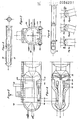
- FIG. 2 shows a floating container 25 which has a cylindrical ship jacket 26, as shown in FIG. 4.
- the floating container 25 is ver with a hemispherical bow 27 see and has a concave, also hemispherical rear 28.
- the cargo tank 30 is concentrically without a rigid connection, as shown in FIGS. 3 and 4.
- the cargo tank is made of aluminum, and the empty spaces 31 between the ship's jacket 26 and cargo tank 30 are foamed with polyurethane for cold insulation.
- the bow hemisphere 27 with the deeper insulating layer 32 assumes the function of a crumple zone in the event of a collision.
- each floating container is provided with a dome structure 33 for liquid breathing. There are also facilities for direct evaporation as well as for charging and extinguishing. Each swimming container is accessible on a longitudinal sun protection sign 34.
- the loading and unloading devices provided on the swimming containers depend on the equipment of the departure or destination port. It is thus possible to provide loading or unloading devices which can be moved to the individual floating container groups at the destination port with a large number of anchorages.
- the swimming containers in addition to central water treatment devices at the destination and departure port, can also be provided with small water treatment systems in order to keep the water in the desired state during transport.
- Floating containers are shown, which are connected to a push unit.
- bolts 35 are provided which engage in corresponding recesses 36 at the rear of a floating container, as can be seen in particular from FIG. These bolts can snap into place automatically when the couplings are retracted and can be triggered by remote control from the push boat. In the event of a collision, the coupling of the affected part of the floating container unit is released automatically.
- the Schu b ship 18 also has a hemispherical bow and corresponding coupling elements.
- FIG. 5 shows a push container unit which has horizontally extending stiffeners 37, into which the bolts 35 engage when coupling. It depends in detail on structural conditions whether the bolts 35 are provided on the bow 32 of the container or on the longitudinal stiffeners 37 in order to then be moved into corresponding recesses.
- FIGS. 6a to 6c show a train container unit in which the towing ship and the individual floating containers are connected by pulling elements 38.
- the individual floating containers have not shown control rudders, which can preferably be operated from the towing ship.
- the tension elements 38 can lengthen and shorten.
- the control movement according to FIG. 6b shortens the pulling element 38a and the pulling element 38b are lengthened, during the control movement according to FIG. 6c the pulling element 38a is lengthened, while the pulling element 38b is shortened. In this way, a lateral control movement as well as a vertical movement of the swimming container by waves are possible to each other.
- the tension elements are thereby under a bias, for example, by spring motors, so that the Schw imm: container are largely held in a supported by the bearing rollers 39 contact. It is also possible to assign the drives (not shown) with slip clutches to pull in or shorten the pulling elements 38.
- FIG. 8 shows a coupling in the form of a ball capsule 55.
- the ball 55 engages in two articulated ball shells which are pulled apart by hydraulic cylinders 56 for uncoupling, so that the ball 55 can be released. In this way, relative movements between the towing vessel 18 and the floating container, as they result from the operation, are made possible.
- a towing ship 18 is shown, as is already shown schematically in FIGS. 1 and 6.
- the towing vessel 18 has drive channels 40, in which drive screws 41 sit, which are connected via shafts 42 to a gear 43 and a gas engine 44.
- the rear outlet openings 45 of the drive channels 40 lie outside the projection of the cylinders
- the floating container 25 can be controlled by differently driving the screws 41, but also additionally by the control flaps 46 which are attached to the outlet openings 45 of the drive channels 40.
- ballast space 48 is provided, which is filled so that the drive ship 18 of the immersion depth 49 of the floating container during liquid gas transport or the immersion depth 50 of the floating container during water transport on the return trip from the destination port 2 adapted to the port of departure 1.
- the floating container is provided with a cylindrical double jacket 26, 57 made of steel, the annular space of which is provided with metal ballast 59 in the lower region.
- This metal ballast can consist of cast iron, lead or another particularly heavy substance.
- the inner jacket 57 carries on the underside a leak pan 64 made of material that is resistant to low temperatures, for example aluminum or lead. This trough is designed to collect any liquid gas escaping from the cargo tank 30.
- the cargo tank is arranged concentrically to the double jacket 26, 57 without a rigid connection, the space between the double jacket 26, 57 and the cargo tank 30 being filled or foamed with an insulating material 31, as already described.
- the cavity located above the metal ballast 59 in the double jacket 26, 57 is not filled during a loading trip in the upper water course. However, if an underwater trip is intended, then part of the cavity above the metal ballast 59 is filled with control ballast water 58d to regulate the water depth, as is shown in the left half in FIG. 10.
- ballast water depending on the desired immersion depth.
- FIG. 11 A further embodiment of a floating container is shown in FIG. 11. This consists of a cylindrical outer jacket 26, which receives metal ballast in the lower region, the space between the outer jacket 26 and the cargo tank 30 being filled with insulating material 31 in the usual way.
- a leak pan 64 made of low-temperature resistant material is provided in the lower part on the inside of the outer jacket 26.
- ballast longitudinal ballast tanks 60 For ballast handling, there are two longitudinal ballast tanks 60 arranged on the left and right in the horizontal plane provided, which preferably have a semicircular cross section.
- the ballast longitudinal tank 60 is not used during the upper water travel during the loading trip shown on the left side of FIG. 11 and is otherwise filled with ballast water 61b in accordance with the desired thawing depth.
- the ballast water 61a is again filled into the longitudinal ballast tank 60 depending on the desired immersion depth.
- the partial longitudinal section shown in FIG. 12 shows the cargo tank 30 which, when using low temperatures, has a shrinkage area 63 which is filled by the elastic insulating material.
- a heating coil 62 is arranged on the dome structure 33 to evaporate the liquid gas.
Priority Applications (1)
| Application Number | Priority Date | Filing Date | Title |
|---|---|---|---|
| AT82100016T ATE14702T1 (de) | 1981-01-10 | 1982-01-05 | Verfahren und einrichtung zum transport von fluessiggas. |
Applications Claiming Priority (2)
| Application Number | Priority Date | Filing Date | Title |
|---|---|---|---|
| DE3100596 | 1981-01-10 | ||
| DE19813100596 DE3100596A1 (de) | 1981-01-10 | 1981-01-10 | Verfahren und einrichtung zum transport von fluessiggas |
Publications (2)
| Publication Number | Publication Date |
|---|---|
| EP0056231A1 true EP0056231A1 (fr) | 1982-07-21 |
| EP0056231B1 EP0056231B1 (fr) | 1985-08-07 |
Family
ID=6122432
Family Applications (1)
| Application Number | Title | Priority Date | Filing Date |
|---|---|---|---|
| EP82100016A Expired EP0056231B1 (fr) | 1981-01-10 | 1982-01-05 | Méthode et arrangement pour le transport de gaz liquéfié |
Country Status (3)
| Country | Link |
|---|---|
| EP (1) | EP0056231B1 (fr) |
| AT (1) | ATE14702T1 (fr) |
| DE (2) | DE3100596A1 (fr) |
Cited By (2)
| Publication number | Priority date | Publication date | Assignee | Title |
|---|---|---|---|---|
| DE3300894A1 (de) * | 1983-01-13 | 1984-07-19 | Ruhrgas LNG Flüssigerdgas Service GmbH, 4300 Essen | Verfahren zum gueter-schiffstransport von einem arktischen hafen zu einem eisfreien hafen sowie transportschiff zum durchfuehren dieses verfahrens |
| EP0119384A1 (fr) * | 1983-01-13 | 1984-09-26 | Ruhrgas LNG Flüssigerdgas Service GmbH | Méthode pour le transport des marchandises avec un navire d'un port arctique à un port sans glace aussi bien qu'un bâtiment de transport |
Citations (10)
| Publication number | Priority date | Publication date | Assignee | Title |
|---|---|---|---|---|
| LU40537A1 (fr) * | 1960-08-31 | 1961-10-23 | ||
| US3016866A (en) * | 1960-09-12 | 1962-01-16 | Harry H Walker | Buoyant pressure vessels for gases |
| DE1182980B (de) * | 1961-02-17 | 1964-12-03 | Weserwerft Schiffs Und Maschb | Lenkschubzug aus zwei oder mehr schwimmenden Fahrzeugen |
| US3280779A (en) * | 1964-09-14 | 1966-10-25 | Breit Eng Inc | Waterborne freight-carrying vehicles |
| DE1244604B (de) * | 1959-12-08 | 1967-07-13 | Chantiers Navals Franco Belges | Kupplung fuer Gelenkzuege aus Fahrzeugen zur selbsttaetigen Wiederausrichtung derselben |
| US3461829A (en) * | 1967-06-09 | 1969-08-19 | Ocean Research & Mfg Co Inc | System and apparatus for connecting and steering pushed vessels |
| DE2248381A1 (de) * | 1971-10-07 | 1973-04-12 | John Joseph Bylo | See-transportsystem |
| DE2234292A1 (de) * | 1972-07-12 | 1974-01-31 | Robert Dail Moss | Seegehender leichter |
| US3910219A (en) * | 1973-10-05 | 1975-10-07 | Aoki Construction | Connecting structure for ocean-going push-barge |
| FR2377931A1 (fr) * | 1977-01-19 | 1978-08-18 | Ledun Bernard | Conteneurs pour hydrocarbures |
-
1981
- 1981-01-10 DE DE19813100596 patent/DE3100596A1/de not_active Withdrawn
-
1982
- 1982-01-05 EP EP82100016A patent/EP0056231B1/fr not_active Expired
- 1982-01-05 AT AT82100016T patent/ATE14702T1/de active
- 1982-01-05 DE DE8282100016T patent/DE3265114D1/de not_active Expired
Patent Citations (12)
| Publication number | Priority date | Publication date | Assignee | Title |
|---|---|---|---|---|
| DE1244604B (de) * | 1959-12-08 | 1967-07-13 | Chantiers Navals Franco Belges | Kupplung fuer Gelenkzuege aus Fahrzeugen zur selbsttaetigen Wiederausrichtung derselben |
| LU40537A1 (fr) * | 1960-08-31 | 1961-10-23 | ||
| US3016866A (en) * | 1960-09-12 | 1962-01-16 | Harry H Walker | Buoyant pressure vessels for gases |
| DE1182980B (de) * | 1961-02-17 | 1964-12-03 | Weserwerft Schiffs Und Maschb | Lenkschubzug aus zwei oder mehr schwimmenden Fahrzeugen |
| US3280779A (en) * | 1964-09-14 | 1966-10-25 | Breit Eng Inc | Waterborne freight-carrying vehicles |
| US3461829A (en) * | 1967-06-09 | 1969-08-19 | Ocean Research & Mfg Co Inc | System and apparatus for connecting and steering pushed vessels |
| DE2248381A1 (de) * | 1971-10-07 | 1973-04-12 | John Joseph Bylo | See-transportsystem |
| DE2234292A1 (de) * | 1972-07-12 | 1974-01-31 | Robert Dail Moss | Seegehender leichter |
| US3910219A (en) * | 1973-10-05 | 1975-10-07 | Aoki Construction | Connecting structure for ocean-going push-barge |
| GB1437744A (fr) * | 1973-10-05 | 1976-06-03 | ||
| CA1018015A (fr) * | 1973-10-05 | 1977-09-27 | Yoshikiyo Kanefusa | Structure de jonction pour pousse-barges de haute mer |
| FR2377931A1 (fr) * | 1977-01-19 | 1978-08-18 | Ledun Bernard | Conteneurs pour hydrocarbures |
Cited By (2)
| Publication number | Priority date | Publication date | Assignee | Title |
|---|---|---|---|---|
| DE3300894A1 (de) * | 1983-01-13 | 1984-07-19 | Ruhrgas LNG Flüssigerdgas Service GmbH, 4300 Essen | Verfahren zum gueter-schiffstransport von einem arktischen hafen zu einem eisfreien hafen sowie transportschiff zum durchfuehren dieses verfahrens |
| EP0119384A1 (fr) * | 1983-01-13 | 1984-09-26 | Ruhrgas LNG Flüssigerdgas Service GmbH | Méthode pour le transport des marchandises avec un navire d'un port arctique à un port sans glace aussi bien qu'un bâtiment de transport |
Also Published As
| Publication number | Publication date |
|---|---|
| ATE14702T1 (de) | 1985-08-15 |
| DE3265114D1 (en) | 1985-09-12 |
| DE3100596A1 (de) | 1982-08-26 |
| EP0056231B1 (fr) | 1985-08-07 |
Similar Documents
| Publication | Publication Date | Title |
|---|---|---|
| DE2233847A1 (de) | Transportanordnung mit einer mehrzahl masseinheitlicher bzw. modulcontainer und verfahren zum behandeln von seeketten mit masseinheitlichen containern | |
| DE2253116A1 (de) | Vorrichtung zum trennen von rohprodukten, die aus produktionssonden fliessen, am boden eines erdoelfeldes im meer | |
| DE2451406B2 (de) | Transportschiff für Schwimmbehalter | |
| DE2309386A1 (de) | Fahrzeug zur befoerderung von lasten ueber eis | |
| DE2133356A1 (de) | Schiffsanlegeplatz in Form einer stabilen Schwimmplattform | |
| DE1866612U (de) | Boot fuer tiefseetauchungen. | |
| DE1506247C3 (de) | Verfahren zum Beladen und Entladen eines Ladungstanks in einem Öltanker | |
| DE3117939A1 (de) | Schiff zur aufnahme von schleppkaehnen | |
| EP0056231B1 (fr) | Méthode et arrangement pour le transport de gaz liquéfié | |
| DE2303381C2 (de) | Schiff | |
| DE2312014C3 (de) | Verfahren zum Ausgleichen des auf einen absenkbaren Lagerbehälter wirkenden Wasserdrucks, sowie absenkbarer Lagerbehälter | |
| DE3143457A1 (de) | Transportsystem fuer den kombinierten inland/ueberseeverkehr | |
| DE4030018C2 (fr) | ||
| WO2011063962A2 (fr) | Transport de gaz cryogène | |
| DE2505721A1 (de) | Verfahren zum speichern von oel aus untersee-bohrungen und zum ueberfuehren von diesem zu und aus tankern und eine hierbei verwendete oelspeicher- und -auslieferungseinrichtung | |
| DE1937425C3 (de) | Tankschiff | |
| DE2420026C2 (de) | Förderschiff für den Meeresbergbau | |
| EP1314640B1 (fr) | Elément flotteur | |
| DE2133674A1 (de) | Frachtschiff | |
| DE4039904C2 (fr) | ||
| WO2008151712A1 (fr) | Bateau de transport de barges | |
| DE2057816A1 (de) | Vorrichtung zur Steuerung der Neigung und Hoehe eines Pontons | |
| DE19820895A1 (de) | Wasserfahrzeug mit Unsinkbarkeitssicherung | |
| DE3506123A1 (de) | Unterwasserstation mit gelenkturm fuer erdoel-, erdgasproduktion, meeresbergbau o.dgl. | |
| DE102019205129A1 (de) | Transport von Fluiden mittels multifunktionalem Transportbehälter |
Legal Events
| Date | Code | Title | Description |
|---|---|---|---|
| PUAI | Public reference made under article 153(3) epc to a published international application that has entered the european phase |
Free format text: ORIGINAL CODE: 0009012 |
|
| AK | Designated contracting states |
Designated state(s): AT BE DE FR GB IT NL |
|
| 17P | Request for examination filed |
Effective date: 19830115 |
|
| ITF | It: translation for a ep patent filed |
Owner name: DE DOMINICIS & MAYER S.R.L. |
|
| GRAA | (expected) grant |
Free format text: ORIGINAL CODE: 0009210 |
|
| AK | Designated contracting states |
Designated state(s): AT BE DE FR GB IT NL |
|
| REF | Corresponds to: |
Ref document number: 14702 Country of ref document: AT Date of ref document: 19850815 Kind code of ref document: T |
|
| REF | Corresponds to: |
Ref document number: 3265114 Country of ref document: DE Date of ref document: 19850912 |
|
| ET | Fr: translation filed | ||
| PG25 | Lapsed in a contracting state [announced via postgrant information from national office to epo] |
Ref country code: AT Effective date: 19860105 |
|
| PG25 | Lapsed in a contracting state [announced via postgrant information from national office to epo] |
Ref country code: BE Effective date: 19860131 |
|
| PLBE | No opposition filed within time limit |
Free format text: ORIGINAL CODE: 0009261 |
|
| STAA | Information on the status of an ep patent application or granted ep patent |
Free format text: STATUS: NO OPPOSITION FILED WITHIN TIME LIMIT |
|
| 26N | No opposition filed | ||
| BERE | Be: lapsed |
Owner name: IWTS CONSULTING ENGINEERS G.M.B.H. Effective date: 19860131 |
|
| PG25 | Lapsed in a contracting state [announced via postgrant information from national office to epo] |
Ref country code: NL Effective date: 19860801 |
|
| NLV4 | Nl: lapsed or anulled due to non-payment of the annual fee | ||
| GBPC | Gb: european patent ceased through non-payment of renewal fee | ||
| PG25 | Lapsed in a contracting state [announced via postgrant information from national office to epo] |
Ref country code: FR Free format text: LAPSE BECAUSE OF NON-PAYMENT OF DUE FEES Effective date: 19880930 |
|
| PG25 | Lapsed in a contracting state [announced via postgrant information from national office to epo] |
Ref country code: GB Free format text: LAPSE BECAUSE OF NON-PAYMENT OF DUE FEES Effective date: 19881121 |
|
| REG | Reference to a national code |
Ref country code: FR Ref legal event code: ST |
|
| PG25 | Lapsed in a contracting state [announced via postgrant information from national office to epo] |
Ref country code: DE Effective date: 19891003 |