EP0056231A1 - Method and arrangement for transporting liquefied gas - Google Patents
Method and arrangement for transporting liquefied gas Download PDFInfo
- Publication number
- EP0056231A1 EP0056231A1 EP82100016A EP82100016A EP0056231A1 EP 0056231 A1 EP0056231 A1 EP 0056231A1 EP 82100016 A EP82100016 A EP 82100016A EP 82100016 A EP82100016 A EP 82100016A EP 0056231 A1 EP0056231 A1 EP 0056231A1
- Authority
- EP
- European Patent Office
- Prior art keywords
- containers
- floating
- port
- gas
- container
- Prior art date
- Legal status (The legal status is an assumption and is not a legal conclusion. Google has not performed a legal analysis and makes no representation as to the accuracy of the status listed.)
- Granted
Links
Images


Classifications
-
- B—PERFORMING OPERATIONS; TRANSPORTING
- B63—SHIPS OR OTHER WATERBORNE VESSELS; RELATED EQUIPMENT
- B63B—SHIPS OR OTHER WATERBORNE VESSELS; EQUIPMENT FOR SHIPPING
- B63B25/00—Load-accommodating arrangements, e.g. stowing, trimming; Vessels characterised thereby
- B63B25/002—Load-accommodating arrangements, e.g. stowing, trimming; Vessels characterised thereby for goods other than bulk goods
- B63B25/006—Load-accommodating arrangements, e.g. stowing, trimming; Vessels characterised thereby for goods other than bulk goods for floating containers, barges or other floating cargo
-
- B—PERFORMING OPERATIONS; TRANSPORTING
- B63—SHIPS OR OTHER WATERBORNE VESSELS; RELATED EQUIPMENT
- B63B—SHIPS OR OTHER WATERBORNE VESSELS; EQUIPMENT FOR SHIPPING
- B63B25/00—Load-accommodating arrangements, e.g. stowing, trimming; Vessels characterised thereby
- B63B25/02—Load-accommodating arrangements, e.g. stowing, trimming; Vessels characterised thereby for bulk goods
- B63B25/08—Load-accommodating arrangements, e.g. stowing, trimming; Vessels characterised thereby for bulk goods fluid
- B63B25/12—Load-accommodating arrangements, e.g. stowing, trimming; Vessels characterised thereby for bulk goods fluid closed
-
- B—PERFORMING OPERATIONS; TRANSPORTING
- B63—SHIPS OR OTHER WATERBORNE VESSELS; RELATED EQUIPMENT
- B63B—SHIPS OR OTHER WATERBORNE VESSELS; EQUIPMENT FOR SHIPPING
- B63B35/00—Vessels or similar floating structures specially adapted for specific purposes and not otherwise provided for
- B63B35/66—Tugs
- B63B35/70—Tugs for pushing
Definitions
- the invention relates to a method for the transport of liquefied gas by means of insulated liquefied gas containers arranged in ships to maintain the low temperatures required for liquefied gas transport, into which the liquefied petroleum gas is filled in at the port of departure and from which the gas is released in the port of destination.
- the invention is therefore based on the object of making available a method for transporting liquefied petroleum gas and corresponding facilities for carrying it out, in which the cost-effectiveness of transporting liquefied petroleum gas is substantially increased while reducing the risk potential.
- the invention is that the gas in the exit port of the liquefaction plant is introduced directly into the ships in the form of floating containers, that the floating containers are moved together in groups to the destination port and that the liquefied gas is evaporated directly from the swimming containers in the destination port.
- the invention proposes that the swimming containers at the destination port be loaded with drinking or industrial water at the destination port, if necessary after flushing with ozone-containing air, and that this is transported on the return trip to the starting port. In this way, the economy of transport is further increased, and drinking and / or industrial water is transported to the area of the departure port, where there is often a great shortage of fresh water, without significant additional costs.
- the measures according to the invention ensure that the specific investments for the provision and the reception capacity in the departure or destination port and for the transport units themselves are significantly reduced.
- Transport energy consumption itself is significantly reduced by combining the floating, container into thrust or pulling units and by designing the hull to be optimal in terms of flow.
- a further increase in profitability is brought about by the lower personnel requirements on land and on board as well as shorter stays in the departure and destination ports.
- the significantly lower retention and takeover capacities lead to a decrease in the hazard potential, and the design of the floating container leads to shorter construction times and to a reduced environmental hazard in the event of accidents.
- the economy of the system is significantly increased by using the ballast trip to transport drinking water.
- Fig. 1 shows a departure port 1 and a destination port 2 is shown schematically.
- a train container unit 3 moves from the starting port 1 to the destination port 2, but can also be designed as a push container unit 4, which moves back from the destination port 2 to the starting port 1 in the drawing.
- a gas liquefaction plant 5 is provided, into which natural gas is supplied through a gas line 6, which is liquefied in the gas liquefaction plant 5 and is introduced into floating containers 8.1, 8.2 and 8.3 via a liquid gas line 7.
- An additional liquefied petroleum gas line 9 leads to two liquefied petroleum gas containers 10, which have only a relatively small storage capacity and only serve to buffer smaller excess amounts.
- the destination port 2 is provided with an evaporation device 11, from which the gas is supplied directly via a gas delivery line 12 can be led to the consumer.
- Containers 13 are also provided for buffering, which can be used as gas storage containers, which can be charged with gas via a gas evaporation system 14, or the liquid gas is fed directly via line 15 into the containers 13, so that these then serve as liquid gas storage containers .
- the capacity of the container 13 is also comparatively low and only serves to buffer gas capacities which can also be supplied to the consumer via the line 16.
- a first floating container group 8.1 to 8.3 can be filled with liquid gas. Such a group is then combined to form a transport unit and moved to the destination port 2.
- a train transport unit is shown, which consists of the floating container group 17.1 to 17.3 and the towing ship 18.
- a floating container group 19.1 to 19.3 shown in the destination port 2 emits a liquefied gas which reaches the gas transport line 12 via each gas evaporation device 11 until the floating containers 19.1 to 19.3 are emptied.
- a drinking water line 20 can be used to fill the emptied swimming containers 19.1 to 19.3 drinking water for transport to the port of departure 1.
- a push container unit 4 is shown, which consists of the floating containers 20.1 to 20.3 and a push ship 21. When the swimming containers loaded with drinking water have arrived at exit 1, the floating containers are emptied via the drinking water line 22.
- Fig. " 1 four groups of swimming containers are shown; preferably, a number of swimming containers divisible by 3 should be provided, so that a swimming container group is loaded at the departure port, a swimming container group is moved to the destination port, while in the meantime a swimming container group is unloaded at the destination port however, four swimming container groups can also be provided according to the time available In each case, a number of anchorages 23 must be provided at departure port 1 and a number of anchorages 24 at destination port 2, which is twice the number of those belonging to a group Floating container.
- a device (not shown) can also be provided, which enables flushing with ozone-containing air before the filling of drinking water via the line 20 into the swimming containers 19.1 to 19.3.
- Ozone is also added to the drinking water to be filled in to the extent that there is still ozone depletion, so that odorless, tasteless and bacteriologically perfect drinking water can be transported according to the WHO standards and delivered to the port of departure.
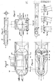
- FIG. 2 shows a floating container 25 which has a cylindrical ship jacket 26, as shown in FIG. 4.
- the floating container 25 is ver with a hemispherical bow 27 see and has a concave, also hemispherical rear 28.
- the cargo tank 30 is concentrically without a rigid connection, as shown in FIGS. 3 and 4.
- the cargo tank is made of aluminum, and the empty spaces 31 between the ship's jacket 26 and cargo tank 30 are foamed with polyurethane for cold insulation.
- the bow hemisphere 27 with the deeper insulating layer 32 assumes the function of a crumple zone in the event of a collision.
- each floating container is provided with a dome structure 33 for liquid breathing. There are also facilities for direct evaporation as well as for charging and extinguishing. Each swimming container is accessible on a longitudinal sun protection sign 34.
- the loading and unloading devices provided on the swimming containers depend on the equipment of the departure or destination port. It is thus possible to provide loading or unloading devices which can be moved to the individual floating container groups at the destination port with a large number of anchorages.
- the swimming containers in addition to central water treatment devices at the destination and departure port, can also be provided with small water treatment systems in order to keep the water in the desired state during transport.
- Floating containers are shown, which are connected to a push unit.
- bolts 35 are provided which engage in corresponding recesses 36 at the rear of a floating container, as can be seen in particular from FIG. These bolts can snap into place automatically when the couplings are retracted and can be triggered by remote control from the push boat. In the event of a collision, the coupling of the affected part of the floating container unit is released automatically.
- the Schu b ship 18 also has a hemispherical bow and corresponding coupling elements.
- FIG. 5 shows a push container unit which has horizontally extending stiffeners 37, into which the bolts 35 engage when coupling. It depends in detail on structural conditions whether the bolts 35 are provided on the bow 32 of the container or on the longitudinal stiffeners 37 in order to then be moved into corresponding recesses.
- FIGS. 6a to 6c show a train container unit in which the towing ship and the individual floating containers are connected by pulling elements 38.
- the individual floating containers have not shown control rudders, which can preferably be operated from the towing ship.
- the tension elements 38 can lengthen and shorten.
- the control movement according to FIG. 6b shortens the pulling element 38a and the pulling element 38b are lengthened, during the control movement according to FIG. 6c the pulling element 38a is lengthened, while the pulling element 38b is shortened. In this way, a lateral control movement as well as a vertical movement of the swimming container by waves are possible to each other.
- the tension elements are thereby under a bias, for example, by spring motors, so that the Schw imm: container are largely held in a supported by the bearing rollers 39 contact. It is also possible to assign the drives (not shown) with slip clutches to pull in or shorten the pulling elements 38.
- FIG. 8 shows a coupling in the form of a ball capsule 55.
- the ball 55 engages in two articulated ball shells which are pulled apart by hydraulic cylinders 56 for uncoupling, so that the ball 55 can be released. In this way, relative movements between the towing vessel 18 and the floating container, as they result from the operation, are made possible.
- a towing ship 18 is shown, as is already shown schematically in FIGS. 1 and 6.
- the towing vessel 18 has drive channels 40, in which drive screws 41 sit, which are connected via shafts 42 to a gear 43 and a gas engine 44.
- the rear outlet openings 45 of the drive channels 40 lie outside the projection of the cylinders
- the floating container 25 can be controlled by differently driving the screws 41, but also additionally by the control flaps 46 which are attached to the outlet openings 45 of the drive channels 40.
- ballast space 48 is provided, which is filled so that the drive ship 18 of the immersion depth 49 of the floating container during liquid gas transport or the immersion depth 50 of the floating container during water transport on the return trip from the destination port 2 adapted to the port of departure 1.
- the floating container is provided with a cylindrical double jacket 26, 57 made of steel, the annular space of which is provided with metal ballast 59 in the lower region.
- This metal ballast can consist of cast iron, lead or another particularly heavy substance.
- the inner jacket 57 carries on the underside a leak pan 64 made of material that is resistant to low temperatures, for example aluminum or lead. This trough is designed to collect any liquid gas escaping from the cargo tank 30.
- the cargo tank is arranged concentrically to the double jacket 26, 57 without a rigid connection, the space between the double jacket 26, 57 and the cargo tank 30 being filled or foamed with an insulating material 31, as already described.
- the cavity located above the metal ballast 59 in the double jacket 26, 57 is not filled during a loading trip in the upper water course. However, if an underwater trip is intended, then part of the cavity above the metal ballast 59 is filled with control ballast water 58d to regulate the water depth, as is shown in the left half in FIG. 10.
- ballast water depending on the desired immersion depth.
- FIG. 11 A further embodiment of a floating container is shown in FIG. 11. This consists of a cylindrical outer jacket 26, which receives metal ballast in the lower region, the space between the outer jacket 26 and the cargo tank 30 being filled with insulating material 31 in the usual way.
- a leak pan 64 made of low-temperature resistant material is provided in the lower part on the inside of the outer jacket 26.
- ballast longitudinal ballast tanks 60 For ballast handling, there are two longitudinal ballast tanks 60 arranged on the left and right in the horizontal plane provided, which preferably have a semicircular cross section.
- the ballast longitudinal tank 60 is not used during the upper water travel during the loading trip shown on the left side of FIG. 11 and is otherwise filled with ballast water 61b in accordance with the desired thawing depth.
- the ballast water 61a is again filled into the longitudinal ballast tank 60 depending on the desired immersion depth.
- the partial longitudinal section shown in FIG. 12 shows the cargo tank 30 which, when using low temperatures, has a shrinkage area 63 which is filled by the elastic insulating material.
- a heating coil 62 is arranged on the dome structure 33 to evaporate the liquid gas.
Abstract
Description
Die Erfindung betrifft ein Verfahren zum Transport von Flüssiggas mittels in Schiffen angeordneter, zur Aufrechterhaltung von zum Flüssiggastransport erforderlichen tiefen Temperaturen isolierter Flüssiggasbehälter, in die das Flüssiggas im Ausgangshafen eingefüllt wird und aus denen im Zielhafen das Gas abgegeben wird.The invention relates to a method for the transport of liquefied gas by means of insulated liquefied gas containers arranged in ships to maintain the low temperatures required for liquefied gas transport, into which the liquefied petroleum gas is filled in at the port of departure and from which the gas is released in the port of destination.
Zu diesem Zweck werden bisher Flüssiggastanker mit einem verhältnismäßig großen Bruttotransportvolumen eingesetzt. Um die Liegezeit im Ausgangshafen sowie im Zielhafen zu begrenzen, ist die Vorhaltung einer sehr großen Menge bereits verflüssigten Gases im Ausgangshafen einerseits und eine entsprechend große Ubernahmekapazität im Zielhafen andererseits notwendig. Neben den dadurch erforderlichen großen Investitionen ist mit den dadurch vorhandenen großen Flüssiggasmengen ein enormes Gefahrenpotential verbunden.So far, liquid gas tankers with a relatively large gross transport volume have been used for this purpose. In order to limit the length of time in the port of departure and in the port of destination, a very large amount of already liquefied gas must be kept in the port of departure on the one hand and a correspondingly large takeover capacity in the destination port on the other. In addition to the large investments required as a result, the large quantities of liquefied gas that are present as a result are associated with an enormous risk potential.
Der Erfindung liegt daher die Aufgabe zugrunde, ein Verfahren zum Transport von Flüssiggas sowie entsprechende Einrichtungen zur Durchführung verfügbar zu machen, bei denen unter Verringerung des Gefahrenpotentials die Wirtschaftlichkeit des Transports von Flüssiggas wesentlich erhöht ist.The invention is therefore based on the object of making available a method for transporting liquefied petroleum gas and corresponding facilities for carrying it out, in which the cost-effectiveness of transporting liquefied petroleum gas is substantially increased while reducing the risk potential.
Die Erfindung besteht darin, daß das Gas im Ausgangshafen von.der Verflüssigungsanlage direkt in die Schiffe in Form von Schwimmcontainern eingeführt wird, daß die Schwimmcontainer in Gruppen zusammengefaßt zum Zielhafen bewegt werden und daß im Zielhafen das Flüssiggas direkt aus den Schwimmcontainern verdampft wird.The invention is that the gas in the exit port of the liquefaction plant is introduced directly into the ships in the form of floating containers, that the floating containers are moved together in groups to the destination port and that the liquefied gas is evaporated directly from the swimming containers in the destination port.
Durch eine entsprechende Anzahl von Schwimmcontainern. werden große Investitionen für Vorratshaltungs- und Aufnahmekapazitäten am Ausgangs- bzw. Zielhafen vermieden, und das Gefahrenpotential - verursacht durch große Flüssiggasvolumen - wird verringert.By an appropriate number of swimming containers. Large investments in storage and reception capacities at the departure or destination port are avoided, and the hazard potential - caused by large volumes of liquid gas - is reduced.
In ihrer weiteren Ausbildung schlägt die Erfindung vor, daß die Schwimmcontainer am Zielhafen, gegebenenfalls nach einer Spülung mit ozonhaltiger Luft, mit Trink- oder Brauchwasser beladen werden und dieses auf der Rückfahrt zum Ausgangshafen transportiert wird. Auf diese Weise wird die Wirtschaftlichkeit des Transports weiter erhöht, und ohne wesentliche Mehrkosten wird Trink- und/oder Brauchwasser in das Gebiet des Ausgangshafens befördert, in dem oft ein großer Mangel an Süßwasser herrscht.In its further development, the invention proposes that the swimming containers at the destination port be loaded with drinking or industrial water at the destination port, if necessary after flushing with ozone-containing air, and that this is transported on the return trip to the starting port. In this way, the economy of transport is further increased, and drinking and / or industrial water is transported to the area of the departure port, where there is often a great shortage of fresh water, without significant additional costs.
Weitere Besonderheiten sowie Einrichtungen zur Durchführung des Verfahrens sind in den Unteransprüchen beansprucht.Further special features as well as facilities for carrying out the method are claimed in the subclaims.
Durch die erfindungsgemäßen Maßnahmen wird erreicht, daß die spezifischen Investitionen für die Vorhaltung und die Aufnahmekapazität im Ausgangs- bzw. Zielhafen sowie für die Transporteinheiten selbst wesentlich verringert sind. Der Transportenergieverbrauch selbst wird durch die Zusammenfassung der .Schwimm-,container zu Schub- oder Zugeinheiten sowie durch eine strömungstechnisch optimale Schiffskörpergestaltung wesentlich verringert . Eine weitere Erhöhung der Wirtschaftlichkeit wird durch den geringeren Personalbedarf an Land und an Bord sowie durch kürzere Aufenthaltszeiten im-Ausgangs- und im Zielhafen bewirkt. Die wesentlich geringeren Vorhalte- und Übernahmekapazitäten führen zu einer Abnahme des Gefahrenpotentials, und die Bauweise der Schwimmcon- tainer führt zu kürzeren Bauzeiten und zu einer eingeschränkten Umweltgefährdung bei Unfällen. Schließlich wird das System durch die Nutzung der Ballastreise zum Transport von Trinkwasser in seiner Wirtschaftlichkeit wesentlich erhöht.The measures according to the invention ensure that the specific investments for the provision and the reception capacity in the departure or destination port and for the transport units themselves are significantly reduced. Transport energy consumption itself is significantly reduced by combining the floating, container into thrust or pulling units and by designing the hull to be optimal in terms of flow. A further increase in profitability is brought about by the lower personnel requirements on land and on board as well as shorter stays in the departure and destination ports. The significantly lower retention and takeover capacities lead to a decrease in the hazard potential, and the design of the floating container leads to shorter construction times and to a reduced environmental hazard in the event of accidents. Finally, the economy of the system is significantly increased by using the ballast trip to transport drinking water.
Die Erfindung soll nachstehend anhand von Ausführungsbeispielen unter Bezugnahme auf die beigefügten Zeichnungen näher erläutert werden.The invention will be explained in more detail below using exemplary embodiments with reference to the accompanying drawings.
In den Zeichnungen zeigen:
- Fig. 1 eine Übersicht in schematischer Darstellung,
- Fig. 2 die Seitenansicht miteinander verbundener Schubcontainer,
- Fig. 3 einen Längsschnit durch die Schwimmcontainer nach Fig. 2,
- Fig. 4 einen Querschnitt durch einen Schwimmcontainer nach Fig. 2,
- Fig. 5 eine Draufsicht auf zwei miteinander verbundene Schubcontainer,
- Fig. 6 in schematischer Darstellung zu einer Zugeinheit verbundene Zugcontainer mit Zugschiff,
- Fig. 7 ein Zugschiff im Längsschnitt,
- Fig. 8 das Antriebssystem eines Zugschiffs nach Fig. 7 im Längsschnitt,
- Fig. 9 einen Querschnitt durch ein Zugschiff nach Fig.8,
- Fig. 10 einen Querschnitt des Schwimmcontainers mit Doppelmantel,
- Fig. 11 einen Querschnitt des Schwimmcontainers mit Ballastlängstanks und
- Fig. 12 einen Längsschnitt des Schwimmcontainers nach Fig. 11.
- 1 is an overview in a schematic representation,
- 2 the side view of interconnected push containers,
- 3 shows a longitudinal section through the floating container according to FIG. 2,
- 4 shows a cross section through a floating container according to FIG. 2,
- 5 is a plan view of two interconnected push containers,
- 6 shows a schematic representation of a train container with a towing ship connected to a train unit,
- 7 is a towing ship in longitudinal section,
- 8 shows the drive system of a towing ship according to FIG. 7 in longitudinal section,
- 9 shows a cross section through a towing vessel according to FIG. 8,
- 10 shows a cross section of the floating container with a double jacket,
- 11 shows a cross section of the floating container with longitudinal ballast tanks and
- 12 shows a longitudinal section of the floating container according to FIG. 11.
19 Fig. 1 ist ein Ausgangshafen 1 und ein Zielhafen 2 schematisch dargestellt. Vom Ausgangshafen 1 zum Zielhafen 2 bewegt sich eine Zugcontainereinheit 3, die aber auch als Schubcontainereinheit 4 ausgebildet sein kann, die sich in der Zeichnung vom Zielhafen 2 zum Ausgangshafen 1 zurückbewegt. Im Ausgangshafen 2 ist eine Gasverflüssigungsanlage 5 vorgesehen, in die durch eine Gasleitung 6 Naturgas zugeführt wird, das in der Gasverflüssigungsanlage 5 verflüssigt wird und über eine Flüssiggasleitung 7 in Schwimmcontainer 8.1, 8.2 und 8.3 eingeführt wird. Eine zusätzliche Flüssiggasleitung 9 führt zu zwei Flüssiggasbehältern 10, die nur eine verhältnismäßig geringe Speicherkapazität aufweisen und lediglich zur Abpufferung geringerer Überschußmengen dienen.1 9 Fig. 1 shows a
Der Zielhafen 2 ist mit je einer Verdampfungsvorrichtung 11 versehen, von der über eine Gasförderleitung 12 das Gas direkt zum Verbraucher geführt werden kann. Ebenfalls zur Abpufferung sind Beh-älter 13 vorgesehen, die als Gasspeicherbehälter benutzt werden können, die über eine Gasverdampfungsanlage 14 mit Gas beschickt werden können, oder das Flüssiggas wird direkt über die Leitung 15 in die Behälter 13 geleitet,so daß diese dann als Flüssiggasspeicherbehälter dienen. Die Kapazität der Behälter 13 ist ebenfalls vergleichsweise gering und dient nur zur Abpufferung von Gaskapazitäten, die über die Leitung 16 ebenfalls dem Verbraucher zugeführt werden können.The
Auf diese Weise kann entsprechend der Kapazität der Gasverflüssigkungsanlage 5 eine ersteSchwimm containergruppe 8.1 bis 8.3 mit Flüssiggas vollgefüllt werden. Eine derartige Gruppe wird dann zu einer Transporteinheit zusammengefaßt und zum Zielhafen 2 bewegt. In der Zeichnung ist eine Zugtransporteinheit dargestellt, die aus der Schwimm.containergruppe 17.1 bis 17.3 und dem Zugschiff 18 besteht. Eine im Zielhafen 2 dargestellte Schwimm.containergruppe 19.1 bis 19.3 gibt das eine Flüssiggas ab,das über je Gasverdampfungsvorrichtung 11 in die Gastransportleitung 12 gelangt, bis die Schwimm.container 19.1 bis 19.3 entleert sind. Über eine Trinkwasserleitung 20 kann in die entleerten Schwimm container 19.1 bis 19.3 Trinkwasser für den Transport in den Ausgangshafen 1 eingefüllt werden. In der Zeichnung ist eine Schubcontainereinheit 4 dargestellt, die aus den Schwimmcontainern 20.1 bis 20.3 und einem Schubschiff 21 besteht. Sind die mit Trinkwasser beladenen Schwimm container am Ausgangshafen 1 angekommen, werden die Schwimmcontainer über die Trinkwasserleitung 22 entleert.In this way, according to the capacity of the
In Fig."1 sind vier Gruppen von Schwimmcontainern dargestellt; vorzugsweise sollte eine durch 3 teilbare Anzahl von Schwimmcontainern vorgesehen werden, so daß eine Schwimmcontainergruppe am Ausgangshafen beladen wird, eine Schwimmcontainergruppe zum Zielhafen bewegt wird, während zwischenzeitlich am Zielhafen eine Schwimmcontainergruppe entladen wird. Je nach der zur Verfügung stehenden Zeit können jedoch auch vier Schwimmcontainergruppen vorgesehen werden. In jedem Fall ist am Ausgangshafen 1 eine Anzahl von Ankerplätzen 23 und am Zielhafen 2 eine Anzahl von Ankerplätzen 24 vorzusehen, die doppelt so groß ist wie die Anzahl der zu einer Gruppe gehörigen Schwimmcontainer.In Fig. " 1 four groups of swimming containers are shown; preferably, a number of swimming containers divisible by 3 should be provided, so that a swimming container group is loaded at the departure port, a swimming container group is moved to the destination port, while in the meantime a swimming container group is unloaded at the destination port however, four swimming container groups can also be provided according to the time available In each case, a number of
Im Zielhafen 2 kann auch eine nicht dargestellte Vorrichtung vorgesehen sein, die vor dem Einfüllen von Trinkwasser über die Leitung 20 in die Schwimmcontainer 19.1 bis 19.3 eine Spülung mit ozonhaltiger Luft ermöglicht. Auf diese Weise werden die Gasreste an den Tankinnenwänden oxydiert. Dem einzufüllenden Trinkwasser wird ebenfalls Ozon in dem Maße zugesetzt, wie noch eine Ozonzehrung besteht, damit ein geruchs-und geschmacksfreies sowie bakteriologisch einwandfreies Trinkwasser nach den Standards der WHO transportiert und am Ausgangshafen angeliefert werden kann.In the
Fig. 2 zeigt einen Schwimmcontainer 25, der einen zylindrischen Schiffsmantel 26 aufweist, wie Fig. 4 zeigt. Der Schwimmcontainer 25 ist mit einem halbkugelförmigen Bug 27 versehen und besitzt ein konkav, ebenfalls halbkugelförmig ausgebildetes Heck 28. Innerhalb der Längs- und Querspanten 29 liegt ohne starre Verbindung konzentrisch der Ladetank 30, wie die Fig. 3 und 4 zeigen. Der Ladetank besteht aus Aluminium,und die Leerräume 31 zwischen Schiffsmantel 26 und Ladetank 30 werden zur Kälteisolierung mit Polyurethan ausgeschäumt. Die Bughalbkugel 27 mit der tieferen Isolierschicht 32 übernimmt im Falle einer Kollision die Funktion einer Knautschzone.FIG. 2 shows a
Wie die Fig. 2 und 4 zeigen, ist jeder Schwimmcontainer mit einem Domaufbau 33 zur Flüssigkeitsatmung versehen. Dort sind auch Einrichtungen zur direkten Verdampfung sowie zur Ladung und Löschung vorgesehen. Auf einem Sonnenschutzlängsschild 34 ist jeder Schwimmcontainer begehbar.As shown in FIGS. 2 and 4, each floating container is provided with a
Die an den Schwimmcontainern vorgesehenen Be- und Entladevorrichtungen hängen von der Ausstattung des Ausgangs- bzw. Zielhafens ab. So ist es möglich, am Zielhafen bei einer großen Anzahl von Ankerplätzen zu den einzelnen Schwimmcontainergruppen bewegbare Verlade- bzw. Entladevorrichtungen vorzusehen. Insbesondere können neben zentralen Wasseraufbereitungsvorrichtungen am Ziel- und Ausgangshafen auch die Schwimmcontainer mit kleinen Wasseraufbereitungsanlagen versehen sein, um das Wasser während des Transports im gewünschten Zustand zu halten.The loading and unloading devices provided on the swimming containers depend on the equipment of the departure or destination port. It is thus possible to provide loading or unloading devices which can be moved to the individual floating container groups at the destination port with a large number of anchorages. In particular, in addition to central water treatment devices at the destination and departure port, the swimming containers can also be provided with small water treatment systems in order to keep the water in the desired state during transport.
In den Fig. 2 und 3 sind .Schwimmcontainer dargestellt,die zu einer Schubeinheit verbunden sind. Zu diesem Zweck sind im Bug 32 eines Schwimmcontainers Bolzen 35 vorgesehen,die in entsprechende Ausnehmungen 36 am Heck eines Schwimmcontainers eingreifen, wie insbesondere aus Fig.3 zu entnehmen ist. Diese Bolzen können automatisch beim Einfahren der Kupplungen einrasten und mittels Fernbedienung vom Schubschiff ausgelöst werden. Im Kollisionsfall löst sich die Kupplung des betroffenen Teils der Schwimm.containereinheit automatisch.2 and 3. Floating containers are shown, which are connected to a push unit. For this purpose In the
Wie aus Fig. 1 zu ersehen ist, besitzt das Schu b schiff 18 ebenfalls einen halbkugelförmigen Bug und entsprechende Kupplungselemente.As can be seen from Fig. 1, the
In Fig. 5 ist eine Schubcontainereinheit dargestellt, die außen horizontal verlaufende Versteifungen 37 aufweist, in die die Bolzen 35 beim Verkuppeln eingreifen. Dabei hängt es im einzelnen von baulichen Gegebenheiten ab, ob die Bolzen 35 am Bug 32 der Container oder an den Längsversteifungen 37 vorgesehen sind, um dann in entsprechende Ausnehmungen bewegt zu werden.5 shows a push container unit which has horizontally extending
In Fig. 6 ist eine Zugcontainereinheit dargestellt, bei der das Zugschiff und die einzelnen Schwimm.container durch Zugelemente 38 verbunden sind. Die einzelnen Schwimm;container weisen nicht dargestellte, vorzugsweise vom Zugschiff aus betätigbare Steuerruder auf. Wie in den Fig. 6a bis 6c dargestellt ist, können sich die Zugelemente 38 verlängern und verkürzen. Bei der Steuerbewegung nach Fig. 6b verkürzt sich das Zugelement 38a,und das Zugelement 38b verlängert sich, während beider Steuerbewegung nach Fig. 6c sich das Zugelement 38a verlängert, während sich das Zugelement 38b verkürzt. Auf diese Art und Weise ist eine seitliche Steuerbewegung wie auch eine durch Wellengang vertikale Bewegung der Schwimm container zueinander möglich. Die Zugelemente stehen dabei unter einer Vorspannung, beispielsweise durch Federmotore, so daß die Schwimm:container weitgehend in einen durch Lagerrollen 39 abgestützten Kontakt gehalten werden. Es ist auch möglich, zum Einziehen bzw. Verkürzen der Zugelemente 38 diesennicht dargestellte Antriebe mit Rutschkupplungen zuzuordnen.6 shows a train container unit in which the towing ship and the individual floating containers are connected by pulling
In Fig. 8 ist eine Kupplung in Form einer Kugelkapsel 55 dargestellt. Die Kugel 55 rastet in zwei gelenkig gelagerten Kugelschalen ein, die durch Hydraulikzylinder 56 zum Entkuppeln auseinandergezogen werden, so daß die Kugel 55 freikommen kann. Auf diese Art und Weise werden Relativbewegungen zwischen Zugschiff 18 und Schwimmcontainer, wie sie der Betrieb mit sich bringt, ermöglicht.8 shows a coupling in the form of a
In den Fig. 7 und 8 ist ein Zugschiff 18 gezeigt, wie es bereits in den Fig. 1 und 6 schematisch dargestellt ist. Das Zugschiff 18 weist Antriebskanäle 40 auf, in denen Antriebsschrauben 41 sitzen, die über Wellen 42 mit einem Getriebe 43 und einem Gasmotor 44 verbunden sind. Wie insbesondere Fig. 9 zeigt, liegen die rückseitigen Austrittsöffnungen 45 der Antriebskanäle 40 außerhalb der Projektion der zylindrischen Schwimmcontainer 25. Eine Steuerung des Antriebs- bzw. Zugschiffs 18 kann durch unterschiedlichen Antrieb der Schrauben 41 erfolgen, aber auch zusätzlich durch die Steuerklappen 46, die an den Ausgangsöffnungen 45 der Antriebskanäle 40 angebracht sind.7 and 8, a towing
Wie im einzelnen Fig. 7 zeigt, sind im Antriebsschiff 18 die Unterkünfte für das gesamte zum Betrieb der Transporteinheit erforderliche Personal vorgesehen. Neben einem Speicherraum 47 für das zum Betrieb der Antriebsmotore 44 erforderliche Flüssiggas ist ein weiterer Ballastraum 48 vorgesehen, der so gefüllt wird, daß das Antriebsschiff 18 der Eintauchtiefe 49 der Schwimmcontainer bei Flüssiggastransport oder der Eintauchtiefe 50 der Schwimmcontainer beim Wassertransport auf der Rückreise vom Zielhafen 2 zum Ausgangshafen 1 angepaßt ist.As shown in detail in FIG. 7, the accommodations for the entire staff required to operate the transport unit are provided in the
In Fig. 10 ist eine weitere Ausführungsform eines Schwimmcontainers dargestellt, der auch für Unterwasserfahrt geeignet ist. Zu diesem Zweck ist der Schwimmcontainer mit einem zylindrischen Doppelmantel 26, 57 aus Stahl versehen, dessen Ringraum im unteren Bereich mit Metallballast 59 versehen ist. Dieser Metallballast kann aus Gußeisen, Blei oder einer anderen besonders schweren Substanz bestehen. Der innere Mantel 57 trägt auf der Unterseite eine Leckwanne 64 aus gegenüber tiefen Temperaturen beständigem Material, z.B. Aluminium oder Blei. Diese Wanne ist dazu bestimmt, eventuell aus dem Ladetank 30 austretendes Flüssiggas aufzufangen. Der Ladetank ist ohne starre Verbindung konzentrisch zu dem Doppelmantel 26, 57 angeordnet, wobei der Raum zwischen Doppelmantel 26, 57 und dem Ladetank 30, wie schon beschrieben mit einem Isoliermaterial 31 ausgefüllt bzw. ausgeschäumt ist.10 shows a further embodiment of a swimming container, which is also suitable for underwater travel. For this purpose, the floating container is provided with a cylindrical
Beim Betrieb wird bei einer Ladereise in Oberwasserfahrt der über dem Metallballast 59 im Doppelmantel 26, 57 befindliche Hohlraum nicht ausgefüllt. Ist jedoch eine Unterwasserfahrt beabsichtigt, dann wird ein Teil des Hohlraumes über dem Metallballast 59 zur Regelung der Wassertiefe mit Regelballastwasser 58d ausgefüllt, wie es in Fig. 10 in der linken Hälfte dargestellt ist.During operation, the cavity located above the
Bei einer Ballastreise, die in Fig. 6 auf der rechten Seite dargestellt ist, wird der über dem Metallballast 59 befindliche Hohlraum je nach der gewünschten Eintauchtiefe mit Ballastwasser gefüllt.During a ballast trip, which is shown on the right in FIG. 6, the cavity located above the
Eine weitere Ausführungsform eines Schwimmcontainers zeigt Fig. 11. Dieser besteht aus einem zylindrischen Außenmantel 26, der im unteren Bereich Metallballast aufnimmt, wobei der Zwischenraum zwischen dem Außenmantel 26 und dem Ladetank 30 in üblicher Weise mit Isoliermaterial 31 ausgefüllt ist. Auch hier ist im unteren Teil auf der Innenseite des Außenmantels 26 eine Leckwanne 64 aus tieftemperaturbeständigem Material vorgesehen.A further embodiment of a floating container is shown in FIG. 11. This consists of a cylindrical
Für die Ballasthandhabung.sind zwei in horizontaler Ebene links und rechts außen angeordnete Ballastlängstanks 60 vorgesehen, die vorzugsweise einen Halbkreisquerschnitt aufweisen. Entsprechend der nach Fig. 10 beschriebenen Funktionsweise wird bei der auf der linken Seite von Fig. 11 dargestellten Ladereise der Ballastlängstank 60 bei Oberwasserfahrt nicht in Anspruch genommen und sonst entsprechend der gewünschten Eintautiefe mit Ballastwasser 61b gefüllt. Bei der auf der rechten Seite in Fig. 11 dargestellten Ballastreise wird das Ballastwasser 61a in den Ballastlängstank 60 wieder je nach gewünschter Eintauchtiefe eingefüllt.For ballast handling, there are two
Der in Fig. 12 dargestellte Teillängsschnitt zeigt den Ladetank 30, der bei Anwendung tiefer Temperaturen einen Schrumpfungsbereich 63 aufweist, der von dem elastischen Isoliermaterial ausgefüllt wird. Zur Verdampfung des Flüssiggases ist an dem Domaufbau 33 eine Heizspirale 62 angeordnet.The partial longitudinal section shown in FIG. 12 shows the
Claims (22)
dadurch gekennzeichnet,
daß das Gas im Ausgangshafen von der Verflüssigungsanlage direkt in Schiffe in Form von Schwimmcontainern eingeführt wird,
daß die Schwimmcontainer in Transportgruppen zusammengefaßt zum Zielhafen bewegt werden und
daß im Zielhafen das Flüssiggas direkt aus den Schwimmcontainern verdampft wird.1. Process for the transport of liquefied petroleum gas by means of liquefied gas containers arranged in ships, insulated to maintain the low temperatures required for liquefied petroleum gas transport, into which the liquefied petroleum gas is filled at the port of departure and from which the gas is released at the port of destination,
characterized,
that the gas in the port of exit from the liquefaction plant is introduced directly into ships in the form of floating containers,
that the floating containers are grouped together in transport groups and moved to the destination port
that the liquefied gas is evaporated directly from the floating containers in the destination port.
dadurch gekennzeichnet, daß eine durch drei teilbare Anzahl von Schwimmcontainern vorgesehen wird,
daß eine erste Gruppe von Schwimmcontainern im Ausgangshafen mit Flüssiggas beladen wird, während eine zweite Gruppe von Schwimmcontainern vom Ausgangshafen zum Zielhafen bewegt wird und eine dritte Gruppe im Zielhafen entladen wird.2. The method according to claim 1,
characterized in that a number of swimming containers divisible by three is provided,
that a first group of swimming containers in the port of departure is loaded with liquefied petroleum gas, while a second group of floating containers is moved from the departure port to the destination port and a third group is unloaded at the destination port.
dadurch gekennzeichnet, daß die Schwimmcontainer beim Bewegen vom Ausgangshafen zum Zielhafen zu einer Schubeinheit zusammengefaßt werden und als Einheit durch ein Schubschiff bewegt werden.• The method according to claim 1 or 2,
characterized in that the floating containers are combined into a push unit when moving from the departure port to the destination port and are moved as a unit by a push ship.
dadurch gekennzeichnet,
daß die Schiffe als zu Einheiten zusammenfaßbare Schwimmcontainer ausgebildet sind, daß die Verladestation mit einer Gasverflüssigkungsanlage versehen ist, die das Flüssiggas direkt in die Schwimmcontainer-abgibt, und daß die Entladestation mit einer Gasverdampfungsanlage versehen ist, die das Flüssiggas direkt aus den Schwimmcontainern zur Verdampfung entnimmt.6. Device for performing the method according to one of claims 1 to 5 with ships in which insulated liquid gas containers are arranged to maintain low temperatures required for the liquid gas, with a loading station for the liquid gas in the port of departure and with an unloading station for the liquid gas in the port of destination,
characterized,
that the ships as floating pools are formed container, that the loading station is provided with a Gasverflüssigkungsanlage that the liquid gas directly into the floating containers - outputs, and in that the unloading station is provided with a gas evaporation plant, which removes the liquid directly from the floating containers for evaporation.
Priority Applications (1)
| Application Number | Priority Date | Filing Date | Title |
|---|---|---|---|
| AT82100016T ATE14702T1 (en) | 1981-01-10 | 1982-01-05 | METHOD AND EQUIPMENT FOR TRANSPORTATION OF LIQUID GAS. |
Applications Claiming Priority (2)
| Application Number | Priority Date | Filing Date | Title |
|---|---|---|---|
| DE19813100596 DE3100596A1 (en) | 1981-01-10 | 1981-01-10 | METHOD AND DEVICE FOR TRANSPORTING LIQUID GAS |
| DE3100596 | 1981-01-10 |
Publications (2)
| Publication Number | Publication Date |
|---|---|
| EP0056231A1 true EP0056231A1 (en) | 1982-07-21 |
| EP0056231B1 EP0056231B1 (en) | 1985-08-07 |
Family
ID=6122432
Family Applications (1)
| Application Number | Title | Priority Date | Filing Date |
|---|---|---|---|
| EP82100016A Expired EP0056231B1 (en) | 1981-01-10 | 1982-01-05 | Method and arrangement for transporting liquefied gas |
Country Status (3)
| Country | Link |
|---|---|
| EP (1) | EP0056231B1 (en) |
| AT (1) | ATE14702T1 (en) |
| DE (2) | DE3100596A1 (en) |
Cited By (2)
| Publication number | Priority date | Publication date | Assignee | Title |
|---|---|---|---|---|
| DE3300894A1 (en) * | 1983-01-13 | 1984-07-19 | Ruhrgas LNG Flüssigerdgas Service GmbH, 4300 Essen | Method of transporting cargo by ship from an arctic harbour to an ice-free harbour as well as a transport ship for carrying out this method |
| EP0119384A1 (en) * | 1983-01-13 | 1984-09-26 | Ruhrgas LNG Flüssigerdgas Service GmbH | Method for the transport of goods with a ship from an arctic harbour to an icefree harbour as well as a transportship |
Citations (10)
| Publication number | Priority date | Publication date | Assignee | Title |
|---|---|---|---|---|
| LU40537A1 (en) * | 1960-08-31 | 1961-10-23 | ||
| US3016866A (en) * | 1960-09-12 | 1962-01-16 | Harry H Walker | Buoyant pressure vessels for gases |
| DE1182980B (en) * | 1961-02-17 | 1964-12-03 | Weserwerft Schiffs Und Maschb | Steering thrust from two or more floating vehicles |
| US3280779A (en) * | 1964-09-14 | 1966-10-25 | Breit Eng Inc | Waterborne freight-carrying vehicles |
| DE1244604B (en) * | 1959-12-08 | 1967-07-13 | Chantiers Navals Franco Belges | Coupling for articulated trains from vehicles for automatic realignment |
| US3461829A (en) * | 1967-06-09 | 1969-08-19 | Ocean Research & Mfg Co Inc | System and apparatus for connecting and steering pushed vessels |
| DE2248381A1 (en) * | 1971-10-07 | 1973-04-12 | John Joseph Bylo | SEA TRANSPORT SYSTEM |
| DE2234292A1 (en) * | 1972-07-12 | 1974-01-31 | Robert Dail Moss | SEAWAY LIGHTER |
| US3910219A (en) * | 1973-10-05 | 1975-10-07 | Aoki Construction | Connecting structure for ocean-going push-barge |
| FR2377931A1 (en) * | 1977-01-19 | 1978-08-18 | Ledun Bernard | Container for transporting hydrocarbon(s) by sea - comprising tank, protecting sleeve e.g. of polyethylene and outer envelope |
-
1981
- 1981-01-10 DE DE19813100596 patent/DE3100596A1/en not_active Withdrawn
-
1982
- 1982-01-05 AT AT82100016T patent/ATE14702T1/en active
- 1982-01-05 EP EP82100016A patent/EP0056231B1/en not_active Expired
- 1982-01-05 DE DE8282100016T patent/DE3265114D1/en not_active Expired
Patent Citations (12)
| Publication number | Priority date | Publication date | Assignee | Title |
|---|---|---|---|---|
| DE1244604B (en) * | 1959-12-08 | 1967-07-13 | Chantiers Navals Franco Belges | Coupling for articulated trains from vehicles for automatic realignment |
| LU40537A1 (en) * | 1960-08-31 | 1961-10-23 | ||
| US3016866A (en) * | 1960-09-12 | 1962-01-16 | Harry H Walker | Buoyant pressure vessels for gases |
| DE1182980B (en) * | 1961-02-17 | 1964-12-03 | Weserwerft Schiffs Und Maschb | Steering thrust from two or more floating vehicles |
| US3280779A (en) * | 1964-09-14 | 1966-10-25 | Breit Eng Inc | Waterborne freight-carrying vehicles |
| US3461829A (en) * | 1967-06-09 | 1969-08-19 | Ocean Research & Mfg Co Inc | System and apparatus for connecting and steering pushed vessels |
| DE2248381A1 (en) * | 1971-10-07 | 1973-04-12 | John Joseph Bylo | SEA TRANSPORT SYSTEM |
| DE2234292A1 (en) * | 1972-07-12 | 1974-01-31 | Robert Dail Moss | SEAWAY LIGHTER |
| US3910219A (en) * | 1973-10-05 | 1975-10-07 | Aoki Construction | Connecting structure for ocean-going push-barge |
| GB1437744A (en) * | 1973-10-05 | 1976-06-03 | ||
| CA1018015A (en) * | 1973-10-05 | 1977-09-27 | Yoshikiyo Kanefusa | Connecting structure for ocean-going push-barge |
| FR2377931A1 (en) * | 1977-01-19 | 1978-08-18 | Ledun Bernard | Container for transporting hydrocarbon(s) by sea - comprising tank, protecting sleeve e.g. of polyethylene and outer envelope |
Cited By (2)
| Publication number | Priority date | Publication date | Assignee | Title |
|---|---|---|---|---|
| DE3300894A1 (en) * | 1983-01-13 | 1984-07-19 | Ruhrgas LNG Flüssigerdgas Service GmbH, 4300 Essen | Method of transporting cargo by ship from an arctic harbour to an ice-free harbour as well as a transport ship for carrying out this method |
| EP0119384A1 (en) * | 1983-01-13 | 1984-09-26 | Ruhrgas LNG Flüssigerdgas Service GmbH | Method for the transport of goods with a ship from an arctic harbour to an icefree harbour as well as a transportship |
Also Published As
| Publication number | Publication date |
|---|---|
| EP0056231B1 (en) | 1985-08-07 |
| ATE14702T1 (en) | 1985-08-15 |
| DE3265114D1 (en) | 1985-09-12 |
| DE3100596A1 (en) | 1982-08-26 |
Similar Documents
| Publication | Publication Date | Title |
|---|---|---|
| DE2233847A1 (en) | TRANSPORT ARRANGEMENT WITH A MORE NUMBER OF UNIFORM OR MODULAR CONTAINER AND METHOD FOR TREATMENT OF SEA CHAINS WITH UNIFORM CONTAINERS | |
| DE2253116A1 (en) | DEVICE FOR SEPARATING RAW PRODUCTS FLOWING FROM PRODUCTION PROBES AT THE BOTTOM OF AN OIL FIELD IN THE SEA | |
| DE2451406B2 (en) | Transport ship for float tanks | |
| DE2309386A1 (en) | VEHICLE FOR TRANSPORTING LOADS OVER ICE | |
| DE2133356A1 (en) | Ship mooring in the form of a stable swimming platform | |
| DE1866612U (en) | BOAT FOR DEEP-SEA DIVING. | |
| DE1506247C3 (en) | Method for loading and unloading a cargo tank in an oil tanker | |
| DE3117939A1 (en) | SHIP TO RECEIVE TOWING | |
| EP0056231B1 (en) | Method and arrangement for transporting liquefied gas | |
| DE2303381C2 (en) | ship | |
| DE2312014C3 (en) | Method for equalizing the water pressure acting on a lowerable storage container, as well as lowerable storage container | |
| DE3143457A1 (en) | Transport system for combined inland/overseas traffic | |
| DE4030018C2 (en) | ||
| WO2011063962A2 (en) | Transport of cryogenic gas | |
| DE2505721A1 (en) | METHOD OF STORING OIL FROM SUBSEA BOREHOLES AND TRANSFERRING IT TO AND FROM TANKERS AND AN OIL STORAGE AND DELIVERY DEVICE USED THEREOF | |
| DE1937425C3 (en) | Tanker | |
| DE2420026C2 (en) | Support ship for marine mining | |
| EP1314640B1 (en) | Float element | |
| DE2133674A1 (en) | Oil transport vessel - for surface or underwater use | |
| DE4039904C2 (en) | ||
| WO2008151712A1 (en) | Barge transport vessel | |
| DE2057816A1 (en) | Device for controlling the inclination and height of a pontoon | |
| DE19820895A1 (en) | Ship, e.g. passenger ship, ferry, dangerous goods freight | |
| DE3506123A1 (en) | Underwater station with articulated tower for crude-oil and natural-gas production, offshore mining or the like | |
| AT81642B (en) | Cargo submarine. Cargo submarine. |
Legal Events
| Date | Code | Title | Description |
|---|---|---|---|
| PUAI | Public reference made under article 153(3) epc to a published international application that has entered the european phase |
Free format text: ORIGINAL CODE: 0009012 |
|
| AK | Designated contracting states |
Designated state(s): AT BE DE FR GB IT NL |
|
| 17P | Request for examination filed |
Effective date: 19830115 |
|
| ITF | It: translation for a ep patent filed |
Owner name: DE DOMINICIS & MAYER S.R.L. |
|
| GRAA | (expected) grant |
Free format text: ORIGINAL CODE: 0009210 |
|
| AK | Designated contracting states |
Designated state(s): AT BE DE FR GB IT NL |
|
| REF | Corresponds to: |
Ref document number: 14702 Country of ref document: AT Date of ref document: 19850815 Kind code of ref document: T |
|
| REF | Corresponds to: |
Ref document number: 3265114 Country of ref document: DE Date of ref document: 19850912 |
|
| ET | Fr: translation filed | ||
| PG25 | Lapsed in a contracting state [announced via postgrant information from national office to epo] |
Ref country code: AT Effective date: 19860105 |
|
| PG25 | Lapsed in a contracting state [announced via postgrant information from national office to epo] |
Ref country code: BE Effective date: 19860131 |
|
| PLBE | No opposition filed within time limit |
Free format text: ORIGINAL CODE: 0009261 |
|
| STAA | Information on the status of an ep patent application or granted ep patent |
Free format text: STATUS: NO OPPOSITION FILED WITHIN TIME LIMIT |
|
| 26N | No opposition filed | ||
| BERE | Be: lapsed |
Owner name: IWTS CONSULTING ENGINEERS G.M.B.H. Effective date: 19860131 |
|
| PG25 | Lapsed in a contracting state [announced via postgrant information from national office to epo] |
Ref country code: NL Effective date: 19860801 |
|
| NLV4 | Nl: lapsed or anulled due to non-payment of the annual fee | ||
| GBPC | Gb: european patent ceased through non-payment of renewal fee | ||
| PG25 | Lapsed in a contracting state [announced via postgrant information from national office to epo] |
Ref country code: FR Free format text: LAPSE BECAUSE OF NON-PAYMENT OF DUE FEES Effective date: 19880930 |
|
| PG25 | Lapsed in a contracting state [announced via postgrant information from national office to epo] |
Ref country code: GB Free format text: LAPSE BECAUSE OF NON-PAYMENT OF DUE FEES Effective date: 19881121 |
|
| REG | Reference to a national code |
Ref country code: FR Ref legal event code: ST |
|
| PG25 | Lapsed in a contracting state [announced via postgrant information from national office to epo] |
Ref country code: DE Effective date: 19891003 |