EP0050764B1 - Druckfluidverteilvorrichtung zur Kühlung eines Formwerkzeugs zur Verarbeitung thermoplastischer Stoffe - Google Patents
Druckfluidverteilvorrichtung zur Kühlung eines Formwerkzeugs zur Verarbeitung thermoplastischer Stoffe Download PDFInfo
- Publication number
- EP0050764B1 EP0050764B1 EP81108060A EP81108060A EP0050764B1 EP 0050764 B1 EP0050764 B1 EP 0050764B1 EP 81108060 A EP81108060 A EP 81108060A EP 81108060 A EP81108060 A EP 81108060A EP 0050764 B1 EP0050764 B1 EP 0050764B1
- Authority
- EP
- European Patent Office
- Prior art keywords
- fluid
- channels
- mould
- channel
- mold
- Prior art date
- Legal status (The legal status is an assumption and is not a legal conclusion. Google has not performed a legal analysis and makes no representation as to the accuracy of the status listed.)
- Expired
Links
Images
Classifications
-
- C—CHEMISTRY; METALLURGY
- C03—GLASS; MINERAL OR SLAG WOOL
- C03B—MANUFACTURE, SHAPING, OR SUPPLEMENTARY PROCESSES
- C03B9/00—Blowing glass; Production of hollow glass articles
- C03B9/30—Details of blowing glass; Use of materials for the moulds
- C03B9/38—Means for cooling, heating, or insulating glass-blowing machines or for cooling the glass moulded by the machine
- C03B9/3875—Details thereof relating to the side-wall, body or main part of the moulds
-
- C—CHEMISTRY; METALLURGY
- C03—GLASS; MINERAL OR SLAG WOOL
- C03B—MANUFACTURE, SHAPING, OR SUPPLEMENTARY PROCESSES
- C03B9/00—Blowing glass; Production of hollow glass articles
- C03B9/30—Details of blowing glass; Use of materials for the moulds
- C03B9/38—Means for cooling, heating, or insulating glass-blowing machines or for cooling the glass moulded by the machine
- C03B9/3816—Means for general supply, distribution or control of the medium to the mould, e.g. sensors, circuits, distribution networks
Definitions
- the invention relates to a distribution device for a pressurized fluid, in particular air, for cooling a mold of a machine for processing thermoplastic materials, in particular molten glass, the mold having at least one divided mold, the mold segments of which are each carried by a mold segment holder and are movable relative to one another, whereby furthermore, fluid distribution means connected to a fluid source are provided with each mold segment holder, and outlet openings of the fluid distribution means can be connected screw-free through an interface for a detachable, screw-free connection defining connection means with inlet openings of fluid channels provided in a wall of the mold.
- the fluid distribution means designed as a distribution tube are each fastened to the mold segment holder designed as a pivotable pliers half.
- Each distributor pipe has only one outlet opening for each shaped segment, in which the connecting means designed as a socket are prestressed by a compression spring and are axially displaceable by the associated shaped segment.
- the socket is located in an inlet opening common to all fluid channels of the mold segment, approximately in the longitudinal center of the mold segment. Cooling air is supplied to the manifold through a supply line attached to the pliers half.
- This known arrangement requires a lot of lateral space and is limited to the supply of the cooling air at only one inlet opening in the longitudinal center of the mold segment. This precludes a differentiated application of pressure fluid to the fluid channels of a mold segment.
- the invention has for its object to ensure a differentiated loading of the fluid channels of each mold segment with cooling fluid with simple, only taking up little space and easy and quick to use means.
- each branch duct supplies only a part of the fluid ducts of the associated molding segment with pressurized fluid, it can be laid inexpensively with the best possible use of the space available on the machine.
- the cross-sectional design of the branch channels can be optimized in order to achieve desired flow conditions of the pressure fluid in the fluid channels.
- the mass of the mold segments can be kept to a minimum. Very short mold change times are achieved. When the mold segments are changed, the fluid distribution box remains on the mold segment holder and the setting of throttle valves which may be provided upstream of the interface can be maintained when the previous mold segment is replaced by a new type of the same type.
- the subchannels according to claim 2 are advantageous in the case of special spatial conditions within the machine and can also make a contribution to achieving special flow conditions in the fluid channels and to simplifying the differentiated loading of the fluid channels.
- the pressure of the pressure fluid can be changed in any case between 0 and 100%.
- the throttle valves can be controlled manually or by motor and in the latter case controlled or regulated.
- the special embodiment according to claim 4 has the advantage that the rocker or a rocker pin forming the pivot bearing of the rocker is relieved of additional construction elements.
- the features of claim 5 offer a particularly simple and direct connection of the fluid distribution box with the inlet openings of the fluid channels.
- a special sealing pressure in the interface is unnecessary, since on the one hand usually a pressure fluid, for. B. cooling air, only a small blower pressure in the order of 50x10 2 Pascal is used in the hollow glass production, and since on the other hand, the mold segment creates an adequate seal at the interface due to its own weight.
- the change of the shape segments is particularly easy with this construction.
- relative movements in the transverse direction between the mold segment and the mold segment holder can be compensated for at the interface. Such transverse movements occur during operation due to the suspension of the mold segments on the mold segment holders, which is usually provided with play in the transverse direction.
- the measures of claim 6 serve a space-saving overall arrangement and the controlled application of pressure fluid to the fluid channels.
- the sub-channels designed as chambers result in a calming of the flow, so that the dynamic portion of the pressure fluid which is detrimental to a uniform application of the fluid channels is rendered ineffective.
- the design according to claim 7 has proven to be very advantageous, in particular in the case of fluid channels according to the aforementioned DE-PS 2 537 037.
- the temperature profile on the surface of the molding segment which comes into contact with the thermoplastic material can be set and maintained in this way with the desired accuracy.
- the features of claim 8 allow easy supply of the fluid channels even when a direct connection of the fluid channels to the outlet openings of the branch channels is not possible for design reasons. Any throttle valves are expediently provided upstream of the interface so that the optimal setting of the throttle valves once found can be maintained when the mold is changed.
- connecting bodies according to claim 9 represent a functionally reliable and maintenance-free connecting element.
- these connecting bodies can also be provided on the fluid distribution box and, with their free edge, each rest on a complementary mating surface of the connecting box surrounding the inlet opening of the associated connecting channel.
- a sufficient sealing pressure can be guaranteed in any case by the measures of claim 10.
- a compression spring can also be provided between the connection body and the connection box or fluid distribution box carrying it.
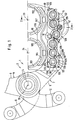
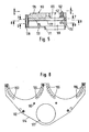
- a vertically standing hinge column 4 is fixedly connected, on which pliers-like holder arms 5 and 6 of mold segment holders 7 and 8 are pivotably mounted.
- the mold segment holder 7 is drawn in its closed position and part of the mold segment holder 8 in its most open position.
- a rear arm 9 is fastened to the holder arm 5 and is articulated in a manner known per se, not shown, via a bolt on a tab.
- a rear arm 12 extends from the holder arm 6 and is coupled to a tab via a bolt. The tabs are each articulated on a crank pin of a crank attached to a drive shaft and can thereby be driven.
- a rocker 19 is pivotably mounted on a rocker pin 18 in a lateral recess 17 (FIG. 2) of the holder arm 5.
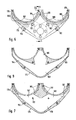
- mold segments 21 In the rocker 19 in each case in a manner known per se, two identical mold segments 21 (FIG. 2) designed as preform halves can be suspended.
- the mold segments 21 are components of a mold 22 designed in this case as a double mold.
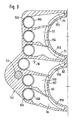
- Each mold segment 21 is provided with three groups of fluid channels 28 to 30 (FIG. 2A) arranged in succession on a circular arc about a longitudinal axis 23 and 24 of the mold segments 21 a wall 31 (FIG. 2) of the shaped segments 21 each lie completely in a plane running through the longitudinal axis 23, 24.
- each mold segment 21 is assigned a split mouth tool 32, the segments of which are mounted on the station 2 in a manner known per se, independently of the mold segment holders 7, 8.
- lower regions of the mold segments 21 overlap upper regions of the closed mouth tools 32.
- blown air is provided as cooling fluid in a manner known per se.
- This pressure fluid flows in the direction of an arrow 33 (FIG. 4) through a feed channel 34 of the machine frame 3.
- a throttle valve 35 can be arranged in a manner known per se, which can be controlled between a fully open and fully closed end position of the feed channel 34 or can be adjusted.
- the pressurized fluid enters a first articulated channel part 36 from the supply channel 34, flows through a second articulated channel part 37 and from there reaches fluid distribution means 38, which will be described in detail later.
- the hinge column 4 forms a first pivot axis 39, to which a second pivot axis 40 runs parallel, about which the first articulated channel part 36 can be pivoted relative to the machine frame 3 while the pressure fluid transfer from the supply channel 34 is always uninterrupted.
- the second joint channel part 37 can be pivoted relative to the first joint channel part 36 about a third pivot axis 41 and relative to the fluid distribution means 38 about a fourth pivot axis 42, which is also shown in FIG. All four pivot axes 39 to 42 run parallel to one another and at a distance from one another.
- the articulated channel parts 36, 37 are pivotally carried by a drive bolt 43 (FIG. 2) which is fastened in the holder arm 5.
- the mold segment holder 8 is equipped with the fluid distribution means 38 corresponding fluid distribution means and with the articulated channel parts 36, 37 corresponding articulated channel parts so that each description of equipment is sufficient.
- the pressure fluid is fed in at the lower end of each mold segment 21.
- the location of the feed into the mold segment depends on the area of greatest heat accumulation in the wall 31 of the mold segment. You will always try to introduce the cooling fluid where the greatest heat is in the wall 31.
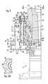
- an elongated mounting plate 123 is screwed to an upper side of the holder arm 5 by means of screws 122, the upper side of which is screwed to locking parts 125 of six locking elements 126 by means of screws 124.
- each locking part 125 has an external toothing 128 on an upwardly extending bushing 127.
- An adjusting bushing 129 is rotatably mounted in the bushing 127, which is provided on the inside with a continuous hub groove 130 and on the top with a collar 132 carrying an external toothing 131 .
- the external toothings 128, 131 have the same pitch and partial circles that are aligned with one another.
- the collar 132 lies on top of the socket 127.
- the adjustment bushing 129 is fixed in the axial direction by a locking ring 132 'which is supported on a shoulder of the locking part 125.
- An adjusting sleeve 133 is rotatably mounted on the outside of the bushing 127 and, with an internal toothing 134 of the same pitch as the external toothing 128, 131, is constantly in engagement with the external toothing 131 and can optionally be brought into engagement with the external toothing 128.
- the adjusting sleeve 133 can be pulled upwards relative to the adjusting bush, where a locking ring 135 as a stop for the internal toothing 134 limits the path. In this raised position of the adjusting sleeve 133, this can be rotated together with the adjusting sleeve 129 because of the continued engagement of the toothings 134, 131.
- a shaft 136 is rotatably carried along by a spring 137.
- the adjusting sleeve 133 with its internal toothing 134 is pushed downward into renewed engagement with the external toothing 128, as can be seen in detail in FIG. 2.
- the rotational movement of the shaft 136 is in any case limited by two stop pins 138 and 139 which extend upward from the locking part 125 and a limiting pin 140 of the adjusting sleeve 133 which cooperates therewith.
- Each shaft 136 is passed through a bore 141 of the holder arm 5 and a bore 142 coaxial therewith in a top wall 143 of a fluid distribution box 144 of the fluid distribution means 38 and carries a pot-shaped throttle valve 145 with a lateral outlet opening 146 at its lower end.
- the throttle valve 145 is in a Fluidver intake opening divider box 144 fitted and is in constant communication with an inlet opening 147 with the interior of a header box 148, the pressure fluid in the direction of arrows 149 through the second joint channel part 37 shown only in Fig. 4 is supplied.
- the outlet tools 32 are blown freely from the collecting box 148 by means of a nozzle device 46 in the direction of an arrow 47 with the pressure fluid.
- a metallic sealing plate 150 is arranged between the collecting box 148 and the fluid distribution box 144.
- the collecting box 148, the sealing plate 150 and the fluid distribution box 144 are connected to one another by screws, not shown, to form a unit forming the fluid distribution means 38, which in turn is screwed to an underside of the holding arm 5 via intermediate pieces 151 (FIG. 7).
- the fluid distribution box 144 has branch channels 62 to 64 and 71 to 73 (FIG. 3). Each branch channel, e.g. B. 63, can be closed according to FIG. 2 by appropriate rotation of the throttle valve 145. Each branch channel, e.g. B. 63, has in the top wall 143 of the fluid distribution box 144 an arc slot outlet opening 153 to 158, which open into a complementary to a connecting surface 159 of the mold segment 21 counter surface 160 of the fluid distribution box 144.
- the connecting surface 159 contains inlet openings of the fluid channels 28 to 30 which are aligned with the outlet openings 153 to 158 (FIG. 2A) and is simply placed on the counter surface 160.
- FIG. 3 shows further details of the fluid distribution box 144 and in particular a cross section through the branch channels 62 to 64 and 71 to 73.
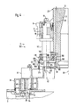
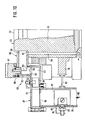
- FIG. 4 shows another embodiment of the distribution device for a finished mold side 197 of the station 2, in which the mold segments 21 are formed by finished mold halves.
- the same parts as in FIGS. 1 to 3 are provided with the same reference numerals below.
- the rocker pin 18 is extended downward by an extension piece 161, to which the drive pin 43 coaxially connects at the bottom for the pivoting movement of the articulated channel parts 36, 37.
- the rocker pin 18 and the drive pin 43 are thus formed in one piece.
- a fluid distribution box 163 is fastened with screws 162, in which branch channels 164 to 168 feeding partial channels 169 and 170 (FIGS. 7 and 9) are formed by separate chambers arranged in mutually parallel planes.
- the fluid distribution box 163 is provided in this order with a bottom wall 172 having an inlet opening 171 for the cooling fluid, a first housing 173 surrounding the sub-channel 169, a metallic sealing washer 174, a second housing 175 surrounding the sub-channel 170 and a top wall 176.
- There is an opening 177 in the sealing disk 174 which enables the pressure fluid to flow over from the sub-channel 169 into the sub-channel 170 to an extent determined by the free cross-sectional area of the opening 177.
- the individual parts of the fluid distribution box 163 are held together by screws 178.
- FIG. 4 shows, as an example, a hole in the hole group 188 in longitudinal section. All bore groups 183 to 186, 187, 188 open into a counter surface 189 of the top wall 176.
- the counter surface 189 is complementary to a lower connecting surface 190 of the mold segments 21, in which all inlet openings of the fluid channels 28 to 30 (see FIG. 2A) are located .
- a sufficient pressure fluid seal between the connecting surface 190 and the counter surface 189 is achieved solely by the weight of the mold segments 21 placed on the counter surface 189. There, in turn, an interface is formed for a detachable and screw-free connection of the mold segments 21 to the pressure fluid distribution device.
- a gap 191 ensures radial mobility between the mold segment 21 and the fluid distribution box 163 to the extent required by the playful suspension of the mold segments 21.
- a shaped segment 77 of a divided single preform is suspended in a shaped segment holder 78 and, together with the latter, can be pivoted about a hinge column, not shown, in accordance with FIG. 1.
- the shaped segment 77 is similar to the shaped segments 21 with groups of axially parallel fluid channels, for. B. 29 provided.
- a feed channel 79 of rectangular cross-sectional area receives pressurized fluid in the direction of an arrow 80, e.g. B. through a hose connected to a cooling air box of the machine frame.
- the feed channel 79 is fastened to the mold segment holder 78 by means of a holder 81 and can be moved together with the latter.
- a throttle valve 83 which is adjustable after loosening a nut 82, the respective throttle position of which can be read by means of a pointer 84 at marks 85 in an outer wall of the feed channel 79.
- the feed channel 79 opens into an inlet opening 86 of a fluid distribution box 87 of fluid distribution means 88.
- the fluid distribution box 87 has three branch channels, of which only the branch channels 63, 64 can be seen in FIG. 10.
- a connection box 89 is attached, which for each of the branch channels, for. B. 63, the fluid distribution box 87 a connecting channel 90 to inlet openings 91 of the fluid channels, for. B. 29 has.
- the fluid channels, e.g. B. 29, are flowed through from top to bottom by the pressure fluid.
- a pot-shaped connecting body 92 is movably inserted in the vertical direction and has a lateral outlet opening 93 in the connecting channel 90.
- the connecting body 92 lies with a free edge 94 on a complementary counter surface 96 of the fluid distribution box 87 surrounding an outlet opening 95 of the associated branch channel 63.
- Each connecting body 92 is also provided with a weight piece 97 which increases the sealing pressure between its free edge 94 and the counter surface 96 and is secured against relative to the connecting box 89 by a pin 98.
- a weight piece 97 which increases the sealing pressure between its free edge 94 and the counter surface 96 and is secured against relative to the connecting box 89 by a pin 98.
- an interface for the releasable, screw-free connection of the connection box 89 to the fluid distribution means 88 is created between the free edge 94 and the counter surface 96.
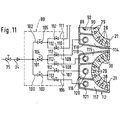
- fluid distribution means 99 are supplied with pressurized fluid through the feed channel 34, which splits into three subchannels 100, 101 and 102, into each of which a throttle valve 103, 104 and 105 is inserted.
- Each sub-channel 100 to 102 feeds two branch channels 106 to 111, which are also each provided with a throttle valve 112.
- a connection box 89 and 113 is fastened to each of the two mold segments 21 of the double mold provided here, the connection channels 90, 114 to 117 of which, each through a cup-shaped connection body 92, 118 to 121, at a screw-free interface with the branch channels 106 to 111, one not shown in detail Fluid distribution box are connected according to FIG. 10.
Landscapes
- Engineering & Computer Science (AREA)
- Chemical & Material Sciences (AREA)
- Manufacturing & Machinery (AREA)
- Materials Engineering (AREA)
- Organic Chemistry (AREA)
- Moulds For Moulding Plastics Or The Like (AREA)
- Blow-Moulding Or Thermoforming Of Plastics Or The Like (AREA)
- Processing And Handling Of Plastics And Other Materials For Molding In General (AREA)
- Saccharide Compounds (AREA)
- Crystals, And After-Treatments Of Crystals (AREA)
- Turning (AREA)
Priority Applications (1)
| Application Number | Priority Date | Filing Date | Title |
|---|---|---|---|
| AT81108060T ATE6354T1 (de) | 1980-10-25 | 1981-10-08 | Druckfluidverteilvorrichtung zur kuehlung eines formwerkzeugs zur verarbeitung thermoplastischer stoffe. |
Applications Claiming Priority (2)
| Application Number | Priority Date | Filing Date | Title |
|---|---|---|---|
| DE3040310A DE3040310C1 (de) | 1980-10-25 | 1980-10-25 | Druckfluidverteilvorrichtung fuer ein Formwerkzeug zur Verarbeitung von Glas und aehnlichen thermoplastischen Stoffen |
| DE3040310 | 1980-10-25 |
Publications (2)
| Publication Number | Publication Date |
|---|---|
| EP0050764A1 EP0050764A1 (de) | 1982-05-05 |
| EP0050764B1 true EP0050764B1 (de) | 1984-02-22 |
Family
ID=6115181
Family Applications (1)
| Application Number | Title | Priority Date | Filing Date |
|---|---|---|---|
| EP81108060A Expired EP0050764B1 (de) | 1980-10-25 | 1981-10-08 | Druckfluidverteilvorrichtung zur Kühlung eines Formwerkzeugs zur Verarbeitung thermoplastischer Stoffe |
Country Status (15)
| Country | Link |
|---|---|
| US (1) | US4388099A (cs) |
| EP (1) | EP0050764B1 (cs) |
| JP (1) | JPS6041009B2 (cs) |
| AT (1) | ATE6354T1 (cs) |
| AU (1) | AU540568B2 (cs) |
| BR (1) | BR8106918A (cs) |
| CA (1) | CA1168453A (cs) |
| CS (1) | CS234033B2 (cs) |
| DE (1) | DE3040310C1 (cs) |
| DK (1) | DK156559C (cs) |
| ES (1) | ES505693A0 (cs) |
| IE (1) | IE52484B1 (cs) |
| MX (1) | MX153569A (cs) |
| SU (1) | SU1131467A3 (cs) |
| ZA (1) | ZA817344B (cs) |
Families Citing this family (39)
| Publication number | Priority date | Publication date | Assignee | Title |
|---|---|---|---|---|
| AU547417B2 (en) * | 1981-02-27 | 1985-10-17 | Emhart Industries Inc. | Mould opening and closing mechanism |
| GB2123401A (en) * | 1982-07-09 | 1984-02-01 | Emhart | Method of cooling a mould |
| GB8307462D0 (en) * | 1983-03-17 | 1983-04-27 | Emhart Ind | Mould for glassware forming machine |
| ZA836051B (en) * | 1982-09-03 | 1985-02-27 | Emhart Ind | Mould arrangement for glassware forming machine |
| IN160666B (cs) * | 1982-09-03 | 1987-07-25 | Emhart Ind | |
| GB2131413B (en) * | 1982-11-30 | 1986-05-29 | Emhart Ind | Bottom plate mechanism for a mould of a glassware container manufacturing machine |
| GB2131415B (en) * | 1982-12-02 | 1986-05-29 | Emhart Ind | Mould arrangement for use in a glassware container manufacturing machine |
| DE3313934C1 (de) * | 1983-04-16 | 1984-04-19 | Heye Hermann Fa | Kuehlvorrichtung fuer ein Formwerkzeug zur Verarbeitung von Glas oder anderen thermoplastischen Stoffen |
| DE3336488A1 (de) * | 1983-10-07 | 1985-04-25 | Veba Glas Ag | Formwerkzeug fuer eine maschine zur verarbeitung schmelzfluessigen glases zu hohlglasartikeln |
| JPS6086040A (ja) * | 1983-10-18 | 1985-05-15 | Ishizuka Glass Ltd | 偏心した口部を有するガラス器の製造方法 |
| GB2151608B (en) * | 1983-12-20 | 1987-01-21 | Emhart Ind | Mould arrangement for a cyclicly operating glassware forming machine |
| GB2152493B (en) * | 1984-01-12 | 1987-02-04 | Emhart Ind | Mould arrangement for use in cyclicly operated glassware forming machine |
| GB2154229B (en) * | 1984-01-25 | 1987-05-07 | Emhart Ind | Cooling arrangement for a mould of a glassware forming machine of the individual section type |
| US4578104A (en) * | 1984-02-27 | 1986-03-25 | Emhart Industries, Inc. | Manufacture of moulded articles of glassware |
| GB2170796B (en) * | 1985-02-13 | 1988-03-16 | Emhart Ind | Mould arrangement for a glassware forming machine |
| GB2172591B (en) * | 1985-03-19 | 1988-07-13 | Emhart Ind | Mould opening and closing mechanism for a glassware forming machine |
| US4690703A (en) * | 1986-04-18 | 1987-09-01 | Emhart Industries, Inc. | Mold cooling arrangement for use in a glassware forming machine |
| USRE34048E (en) * | 1986-05-05 | 1992-09-01 | I.M.T.E.C. Enterprises, Inc. | Cooling system for a glassware forming machine |
| US4750929A (en) * | 1987-02-03 | 1988-06-14 | Liberty Glass Company | Cooling system for a glassware forming machine |
| US4842637A (en) * | 1987-06-26 | 1989-06-27 | Glass Technology Development Corp. | Glassware forming machine with cooling system |
| JPS6450402A (en) * | 1987-08-20 | 1989-02-27 | Murata Manufacturing Co | Variable resistor |
| JPH0217805U (cs) * | 1988-07-19 | 1990-02-06 | ||
| US4909823A (en) * | 1989-05-30 | 1990-03-20 | Liberty Glass Company | Glassware forming machine with cooling system |
| JPH03228833A (ja) * | 1989-10-27 | 1991-10-09 | Toyo Glass Co Ltd | ガラス容器成形機の粗型冷却装置 |
| FR2658500B1 (fr) | 1990-02-21 | 1993-05-14 | Saint Gobain Emballage | Refroidissement des ebaucheurs des machines de verre creux. |
| US5304229A (en) * | 1990-11-13 | 1994-04-19 | I.M.T.E.C. Enterprises, Inc. | Glassware forming machine with cooling system |
| DE4118682C1 (cs) * | 1991-06-07 | 1992-06-04 | Fa. Hermann Heye, 3063 Obernkirchen, De | |
| US5330551A (en) * | 1992-12-02 | 1994-07-19 | I.M.T.E.C. Enterprises, Inc. | Glassware forming machine with cooling system |
| US5656051A (en) * | 1993-06-14 | 1997-08-12 | Vidriera Monterrey, S.A. | Cooling method and mold arrangement for the manufacture of glass articles |
| US7698907B1 (en) * | 1996-07-15 | 2010-04-20 | Owens-Brockway Glass Container Inc. | Mold assembly for glass articles |
| US6109063A (en) * | 1999-03-02 | 2000-08-29 | Emhart Glass S.A. | I.S. machine |
| DE29916216U1 (de) * | 1999-09-15 | 2000-02-10 | Fa. Hermann Heye, 31683 Obernkirchen | Vorrichtung zum Antrieb zweier Formhälftenhalter einer Glasformmaschine |
| US6442976B1 (en) | 2000-02-24 | 2002-09-03 | Owens-Brockway Glass Container Inc. | Liquid cooling of glassware molds |
| US6668591B2 (en) * | 2001-07-17 | 2003-12-30 | Owens-Brockway Plastic Products Inc. | Liquid cooling of glassware molds |
| US6705122B2 (en) * | 2001-08-07 | 2004-03-16 | Owens-Brockway Glass Container Inc. | Method and apparatus for controlling temperature of cooling air for glass manufacturing machine |
| EP1491508B1 (en) * | 2003-06-04 | 2006-08-09 | BDF HOLDING S.p.A. | Machine for producing hollow glass with a system for conveying mould cooling air |
| US7134301B2 (en) * | 2003-04-28 | 2006-11-14 | Emhart Glass S.A. | Mold support mechanism for an I.S. machine |
| US8047022B2 (en) * | 2007-05-16 | 2011-11-01 | Owens-Brockway Glass Container Inc. | Apparatus for opening and closing molds in a glassware forming machine |
| US20250296865A1 (en) * | 2024-03-25 | 2025-09-25 | Owens-Brockway Glass Container Inc. | Cooling system for a glass forming machine |
Family Cites Families (11)
| Publication number | Priority date | Publication date | Assignee | Title |
|---|---|---|---|---|
| US2485836A (en) * | 1947-09-10 | 1949-10-25 | Hartford Empire Co | Glassware mold cooling means |
| US3586491A (en) * | 1969-04-23 | 1971-06-22 | Owens Illinois Inc | Mold cooling apparatus for glass forming machine |
| US3653870A (en) * | 1970-03-09 | 1972-04-04 | Emhart Corp | Holding and cooling device for glassware molds |
| US3666433A (en) * | 1970-07-08 | 1972-05-30 | Emhart Corp | Mold holder with thermostatically controlled mold |
| US3617232A (en) * | 1970-08-31 | 1971-11-02 | Anchor Hocking Corp | Self-acting connector for applying coolant air to glass molds |
| DE2114723C3 (de) * | 1971-03-26 | 1979-01-18 | Owens-Illinois, Inc., Toledo, Ohio (V.St.A.) | Vorrichtung zur Halterung und Kühlung mehrerer geteilter Glasformen |
| US3849101A (en) * | 1972-11-06 | 1974-11-19 | Emhart Corp | Cooling system for glass forming mold |
| US4009018A (en) * | 1975-07-07 | 1977-02-22 | Emhart Industries, Inc. | Glassware forming machine of the I. S. type with in-line mold motion |
| DE2537037C3 (de) * | 1975-08-20 | 1978-07-13 | Fa. Hermann Heye, 3063 Obernkirchen | Fluidgekühltes Formwerkzeug für schmelzflüssiges Glas |
| CA1076868A (en) * | 1975-09-26 | 1980-05-06 | Walter V. Marbach | Piercing blade temperature control |
| US4142884A (en) * | 1977-12-27 | 1979-03-06 | Owens-Illinois, Inc. | Fluid cooling of glass molds |
-
1980
- 1980-10-25 DE DE3040310A patent/DE3040310C1/de not_active Expired
-
1981
- 1981-09-22 ES ES505693A patent/ES505693A0/es active Granted
- 1981-09-28 DK DK429181A patent/DK156559C/da not_active IP Right Cessation
- 1981-09-29 AU AU75736/81A patent/AU540568B2/en not_active Ceased
- 1981-10-08 EP EP81108060A patent/EP0050764B1/de not_active Expired
- 1981-10-08 AT AT81108060T patent/ATE6354T1/de not_active IP Right Cessation
- 1981-10-16 CS CS817616A patent/CS234033B2/cs unknown
- 1981-10-19 US US06/312,851 patent/US4388099A/en not_active Expired - Lifetime
- 1981-10-21 CA CA000388419A patent/CA1168453A/en not_active Expired
- 1981-10-22 MX MX189769A patent/MX153569A/es unknown
- 1981-10-23 SU SU813345905A patent/SU1131467A3/ru active
- 1981-10-23 IE IE2490/81A patent/IE52484B1/en not_active IP Right Cessation
- 1981-10-23 JP JP56169959A patent/JPS6041009B2/ja not_active Expired
- 1981-10-23 ZA ZA817344A patent/ZA817344B/xx unknown
- 1981-10-23 BR BR8106918A patent/BR8106918A/pt not_active IP Right Cessation
Also Published As
| Publication number | Publication date |
|---|---|
| EP0050764A1 (de) | 1982-05-05 |
| ES8206398A1 (es) | 1982-08-16 |
| US4388099A (en) | 1983-06-14 |
| IE812490L (en) | 1982-04-25 |
| ATE6354T1 (de) | 1984-03-15 |
| ES505693A0 (es) | 1982-08-16 |
| JPS6041009B2 (ja) | 1985-09-13 |
| BR8106918A (pt) | 1982-07-13 |
| JPS57129829A (en) | 1982-08-12 |
| MX153569A (es) | 1986-11-21 |
| ZA817344B (en) | 1982-10-27 |
| IE52484B1 (en) | 1987-11-11 |
| DK429181A (da) | 1982-04-26 |
| AU7573681A (en) | 1982-05-06 |
| CS234033B2 (en) | 1985-03-14 |
| SU1131467A3 (ru) | 1984-12-23 |
| DE3040310C1 (de) | 1982-03-25 |
| DK156559B (da) | 1989-09-11 |
| DK156559C (da) | 1990-01-29 |
| CA1168453A (en) | 1984-06-05 |
| AU540568B2 (en) | 1984-11-22 |
Similar Documents
| Publication | Publication Date | Title |
|---|---|---|
| EP0050764B1 (de) | Druckfluidverteilvorrichtung zur Kühlung eines Formwerkzeugs zur Verarbeitung thermoplastischer Stoffe | |
| EP0052223B1 (de) | Kühlvorrichtung für ein Formwerkzeug | |
| DE2623106B2 (de) | LS. Glaswarenformmaschine mit geradliniger Bewegung der Formen | |
| DE2051396C3 (de) | Vorrichtung zum Kühlen von in einem Formhalter lösbar befestigten Külbelformen | |
| DE3883312T2 (de) | Maschine zum Herstellen von Glasgegenständen. | |
| DE69208082T2 (de) | Verfahren und Vorrichtung zum Kühlen einer Matrize | |
| DE3346466A1 (de) | Vorrichtung zum gleichzeitigen oeffnen und schliessen von mehreren parison-formen in einem begrenzten raum | |
| EP0125488A1 (de) | Kühlvorrichtung für ein Formwerkzeug zur Verarbeitung von Glas oder anderen thermoplastischen Stoffen | |
| AT398635B (de) | Vorrichtung zur portionierten abgabe von fliessfähigen massen | |
| EP0542935B1 (de) | Vorrichtung zum kühlen der mündungsformen einer glasformmaschine | |
| DE917357C (de) | Spritzapparat zum Spritzen von mehr oder weniger dickfluessigen Materialien | |
| DE1577880A1 (de) | Einrichtung zum UEberziehen von Gegenstaenden durch elektrostatische Zerstaeubung | |
| DE3039312C2 (cs) | ||
| DE3123488C1 (de) | Aufnahmevorrichtung für Formböden von Formwerkzeugen für thermoplastische Stoffe, insbesondere schmelzflüssiges Glas | |
| DE69104513T2 (de) | Kühlungen für Vorformen von Hohlglasmaschinen. | |
| DE60111435T2 (de) | Flüssigkeitskühlung von Glasformen | |
| DE69415451T2 (de) | Montagemittel für eine Vorformboden oder ähnliches in eine Maschine zum Herstellen von Glasgegenständen | |
| EP3510001A1 (de) | Form- und mündungskühlungsanordnung für eine glasformmaschine | |
| DE69623136T2 (de) | Formkühlvorrichtung für die glasindustrie und verfahren zum herstellen und anpassen dieser kühlvorrichtung an verschiedenen formen | |
| DE3040356C1 (de) | Vorrichtung zur Verteilung von Kuehlfluid ueber ein Formwerkzeug einer Maschine zur Verarbeitung von schmelzfluessigem Glas oder aehnlichen thermoplastischen Stoffen | |
| DE8028499U1 (de) | Druckfluidverteilvorrichtung für ein Formwerkzeug | |
| DE1292801B (de) | Vorrichtung zum Abgeben von geschmolzenem Glas | |
| DE3937538A1 (de) | Verfahren und maschine zur gleichzeitigen herstellung von zwei kontinuierlichen zigarettenstraengen | |
| DE2411316A1 (de) | Spruehvorrichtung | |
| DE3637552C1 (en) | Device for cooling a mouth mould (neck ring) of a glass-moulding machine |
Legal Events
| Date | Code | Title | Description |
|---|---|---|---|
| PUAI | Public reference made under article 153(3) epc to a published international application that has entered the european phase |
Free format text: ORIGINAL CODE: 0009012 |
|
| AK | Designated contracting states |
Designated state(s): AT BE CH FR GB IT LU NL SE |
|
| 17P | Request for examination filed |
Effective date: 19820402 |
|
| ITF | It: translation for a ep patent filed | ||
| GRAA | (expected) grant |
Free format text: ORIGINAL CODE: 0009210 |
|
| AK | Designated contracting states |
Designated state(s): AT BE CH FR GB IT LI LU NL SE |
|
| REF | Corresponds to: |
Ref document number: 6354 Country of ref document: AT Date of ref document: 19840315 Kind code of ref document: T |
|
| ET | Fr: translation filed | ||
| PLBE | No opposition filed within time limit |
Free format text: ORIGINAL CODE: 0009261 |
|
| STAA | Information on the status of an ep patent application or granted ep patent |
Free format text: STATUS: NO OPPOSITION FILED WITHIN TIME LIMIT |
|
| 26N | No opposition filed | ||
| PGFP | Annual fee paid to national office [announced via postgrant information from national office to epo] |
Ref country code: LU Payment date: 19920826 Year of fee payment: 12 |
|
| PGFP | Annual fee paid to national office [announced via postgrant information from national office to epo] |
Ref country code: AT Payment date: 19921030 Year of fee payment: 12 |
|
| ITTA | It: last paid annual fee | ||
| PGFP | Annual fee paid to national office [announced via postgrant information from national office to epo] |
Ref country code: NL Payment date: 19921031 Year of fee payment: 12 |
|
| EPTA | Lu: last paid annual fee | ||
| PGFP | Annual fee paid to national office [announced via postgrant information from national office to epo] |
Ref country code: BE Payment date: 19930812 Year of fee payment: 13 |
|
| PG25 | Lapsed in a contracting state [announced via postgrant information from national office to epo] |
Ref country code: LU Free format text: LAPSE BECAUSE OF NON-PAYMENT OF DUE FEES Effective date: 19931008 Ref country code: AT Effective date: 19931008 |
|
| PG25 | Lapsed in a contracting state [announced via postgrant information from national office to epo] |
Ref country code: NL Effective date: 19940501 |
|
| NLV4 | Nl: lapsed or anulled due to non-payment of the annual fee | ||
| PGFP | Annual fee paid to national office [announced via postgrant information from national office to epo] |
Ref country code: CH Payment date: 19941004 Year of fee payment: 14 |
|
| PG25 | Lapsed in a contracting state [announced via postgrant information from national office to epo] |
Ref country code: BE Effective date: 19941031 |
|
| EAL | Se: european patent in force in sweden |
Ref document number: 81108060.5 |
|
| BERE | Be: lapsed |
Owner name: HEYE HERMANN Effective date: 19941031 |
|
| PG25 | Lapsed in a contracting state [announced via postgrant information from national office to epo] |
Ref country code: LI Effective date: 19951031 Ref country code: CH Effective date: 19951031 |
|
| REG | Reference to a national code |
Ref country code: CH Ref legal event code: PL |
|
| PGFP | Annual fee paid to national office [announced via postgrant information from national office to epo] |
Ref country code: SE Payment date: 19970908 Year of fee payment: 17 |
|
| PGFP | Annual fee paid to national office [announced via postgrant information from national office to epo] |
Ref country code: GB Payment date: 19970929 Year of fee payment: 17 |
|
| PGFP | Annual fee paid to national office [announced via postgrant information from national office to epo] |
Ref country code: FR Payment date: 19970930 Year of fee payment: 17 |
|
| PG25 | Lapsed in a contracting state [announced via postgrant information from national office to epo] |
Ref country code: GB Free format text: LAPSE BECAUSE OF NON-PAYMENT OF DUE FEES Effective date: 19981008 |
|
| PG25 | Lapsed in a contracting state [announced via postgrant information from national office to epo] |
Ref country code: SE Free format text: LAPSE BECAUSE OF NON-PAYMENT OF DUE FEES Effective date: 19981009 |
|
| GBPC | Gb: european patent ceased through non-payment of renewal fee |
Effective date: 19981008 |
|
| EUG | Se: european patent has lapsed |
Ref document number: 81108060.5 |
|
| PG25 | Lapsed in a contracting state [announced via postgrant information from national office to epo] |
Ref country code: FR Free format text: LAPSE BECAUSE OF NON-PAYMENT OF DUE FEES Effective date: 19990630 |
|
| REG | Reference to a national code |
Ref country code: FR Ref legal event code: ST |