EP0050737A1 - Umlenkeinrichtung für einen bandförmigen Aufzeichnungsträger, insbesondere für ein Magnetband - Google Patents
Umlenkeinrichtung für einen bandförmigen Aufzeichnungsträger, insbesondere für ein Magnetband Download PDFInfo
- Publication number
- EP0050737A1 EP0050737A1 EP81107455A EP81107455A EP0050737A1 EP 0050737 A1 EP0050737 A1 EP 0050737A1 EP 81107455 A EP81107455 A EP 81107455A EP 81107455 A EP81107455 A EP 81107455A EP 0050737 A1 EP0050737 A1 EP 0050737A1
- Authority
- EP
- European Patent Office
- Prior art keywords
- roller
- tape
- deflection
- belt
- roll
- Prior art date
- Legal status (The legal status is an assumption and is not a legal conclusion. Google has not performed a legal analysis and makes no representation as to the accuracy of the status listed.)
- Granted
Links
- 230000002401 inhibitory effect Effects 0.000 claims description 7
- 230000001133 acceleration Effects 0.000 claims description 3
- 230000002093 peripheral effect Effects 0.000 abstract description 2
- 238000004804 winding Methods 0.000 description 5
- 238000005259 measurement Methods 0.000 description 4
- 238000010586 diagram Methods 0.000 description 3
- 230000000694 effects Effects 0.000 description 3
- 230000015572 biosynthetic process Effects 0.000 description 2
- 230000002349 favourable effect Effects 0.000 description 2
- 210000004209 hair Anatomy 0.000 description 2
- 238000004519 manufacturing process Methods 0.000 description 2
- 239000002184 metal Substances 0.000 description 2
- 238000000034 method Methods 0.000 description 2
- 230000003746 surface roughness Effects 0.000 description 2
- 238000012423 maintenance Methods 0.000 description 1
- 230000007257 malfunction Effects 0.000 description 1
- 238000011160 research Methods 0.000 description 1
- 230000007704 transition Effects 0.000 description 1
- 230000001960 triggered effect Effects 0.000 description 1
Images

Classifications
-
- G—PHYSICS
- G11—INFORMATION STORAGE
- G11B—INFORMATION STORAGE BASED ON RELATIVE MOVEMENT BETWEEN RECORD CARRIER AND TRANSDUCER
- G11B15/00—Driving, starting or stopping record carriers of filamentary or web form; Driving both such record carriers and heads; Guiding such record carriers or containers therefor; Control thereof; Control of operating function
- G11B15/18—Driving; Starting; Stopping; Arrangements for control or regulation thereof
- G11B15/22—Stopping means
-
- G—PHYSICS
- G11—INFORMATION STORAGE
- G11B—INFORMATION STORAGE BASED ON RELATIVE MOVEMENT BETWEEN RECORD CARRIER AND TRANSDUCER
- G11B15/00—Driving, starting or stopping record carriers of filamentary or web form; Driving both such record carriers and heads; Guiding such record carriers or containers therefor; Control thereof; Control of operating function
- G11B15/18—Driving; Starting; Stopping; Arrangements for control or regulation thereof
- G11B15/26—Driving record carriers by members acting directly or indirectly thereon
- G11B15/28—Driving record carriers by members acting directly or indirectly thereon through rollers driving by frictional contact with the record carrier, e.g. capstan; Multiple arrangements of capstans or drums coupled to means for controlling the speed of the drive; Multiple capstan systems alternately engageable with record carrier to provide reversal
- G11B15/295—Driving record carriers by members acting directly or indirectly thereon through rollers driving by frictional contact with the record carrier, e.g. capstan; Multiple arrangements of capstans or drums coupled to means for controlling the speed of the drive; Multiple capstan systems alternately engageable with record carrier to provide reversal with single capstan or drum simultaneously driving the record carrier at two separate points of an isolated part thereof, e.g. the capstan acting directly on the tape rollers
-
- G—PHYSICS
- G11—INFORMATION STORAGE
- G11B—INFORMATION STORAGE BASED ON RELATIVE MOVEMENT BETWEEN RECORD CARRIER AND TRANSDUCER
- G11B15/00—Driving, starting or stopping record carriers of filamentary or web form; Driving both such record carriers and heads; Guiding such record carriers or containers therefor; Control thereof; Control of operating function
- G11B15/60—Guiding record carrier
- G11B15/605—Guiding record carrier without displacing the guiding means
Definitions
- the invention relates to a deflection device for a tape-shaped recording medium, in particular a magnetic tape which is subjected to strong accelerations in its longitudinal direction, in which at least one deflection roller rotatable on a bearing device is provided, over which the transported tape is guided.
- Such a deflection device is said to be usable in particular in magnetic tape devices (so-called high-speed drives) working after the contact winding drives.
- the deflection device according to the invention to be described below can be used particularly advantageously.
- DE-PS 705 813 It is also known from DE-PS 705 813 for a sound film device to provide a brake roller for the film in front of the sound reel, so that the film on the sound reel receives the required tension for carrying the flywheel mass, and thus the occurrence of slippage is avoided.
- US Pat. No. 3,593,945 also discloses a magnetic tape drive based on the contact winding principle ("high-speed runner") in which fixed guide pins are used. The tape inevitably comes into contact with the guide surface and wear and malfunctions occur in the tape run.
- the object of the present invention is to improve the deflection devices, in particular for high-speed magnetic tape devices, in order to reduce the interference signals during recording / playback of recorded signals with the least possible effort.
- This object is surprisingly achieved when an inhibiting torque between the roller and the bearing device is generated on the deflection device according to the introduction, the size of which corresponds to a frictional force acting on the roller circumference of between 2 and 15 p, preferably between 2 and 10 p.
- the roll is fixed above a minimum tape transport speed and essentially only rotates if the latter sticks to this surface as a result of a very smooth formation of the contact surface between the roll and tape, which is known as a slip-stick effect, or if the minimum speed of the belt is not reached.
- the effect that the roll stops during tape transport is consciously brought about according to the invention, although it is avoided by all means in all previously known magnetic tape drives, as the prior art cited above shows.
- the solution according to the invention can also be implemented with little effort.
- roll runout can be compensated.
- the roller can be designed with a surface roughness Ra of less than 0.5 / ⁇ m, in particular less than 0.28 / ⁇ m. This reduces the friction of the air on the roller surface and favors the creation of an interface between the belt and the roller.
- the deflection roller can be provided with height guide flanges, which can also be firmly connected to the bearing device. These flanges can also extend only around a part of the circumference of the roller and have inlet and outlet chamfers for the belt.
- either a single or two deflection rollers can be provided, the magnetic head being between each Belt roll and pulley or between the pulleys is to be arranged.
- the formation of the boundary layer is most favorable when the roller is stationary, because then the frictional force which is indirectly exerted on the roller by the belt is just being compensated. If the speed required to form the boundary layer is undershot, the role is also increased due to the increase in the indirect frictional force exerted on the role. rotates, which prevents slippage between the roll and belt.
- a high-speed drive 5 consists essentially of the drive roller 6, which is arranged between the reel 7 and the unwind 8 and in the given direction of rotation a) drives the reel in the direction b) and the unwind in the direction c).
- a deflection roller 9 is arranged on a common axis and in the same plane with the drive roller 6, over the circumference of which the belt 10 is guided.
- at least one recording and / or scanning can be carried out on the free tape length between the drive and the deflection roller 6 or 9 head 11 may be arranged.
- the head 11 is arranged inside or outside the band loop. In the present case, since the film side of the band 10 is wound inwards on the windings, the head 11 is provided within the loop.
- the up and unwinding 7 and 8 which are pressed onto the roller 5 by means of pressure devices (not shown), are driven almost without slippage, as a result of which high-speed tape transport, in particular for thin and very thin magnetic tapes with a total thickness of 15 / u or 9 / u or below, is achievable.
- the deflection roller 9 has in each case height guide flanges 12 for the band 10, which are either designed as rotating flanges (Fig. 3) or as fixed flanges (Fig. 2).
- the belt flutter influences can be reduced when the roll is braked in a defined manner and when the roll is braked to a stop stood for tape run, the time base errors otherwise generated by the reel can be completely eliminated.
- the cause of this considerable improvement is considered to be the creation of a boundary layer which enables the tape to be transported on an air layer over the roller surface.
- a residual coefficient of friction after the boundary layer has been generated is applied as an inhibiting moment on the roll in order to achieve a roll standstill at and above a minimum belt speed which is approximately in the range of 2-4 m / s.
- a cylindrical deflection roller 13 is fixedly connected to an axis 15 rotatably mounted in bearings 14.
- the bearings 14 are provided in chassis parts 16 of the drive 5.
- height guide flange 17 are also firmly connected, which are arranged at least in the wrapping area of the belt 10.
- a metal disk 18 can be attached, which protrudes into the air gap of a permanent magnet or electromagnet device 19.
- a metal disk 18 can be attached, which protrudes into the air gap of a permanent magnet or electromagnet device 19.
- an eddy current brake or a hysteresis brake is created, the braking force of which is either fixed accordingly with a permanent magnet or variably adjustable with an electromagnet.
- FIG. 3 shows a hat-shaped roller 20 with integrated flanges 21 on a permanently connected axle 22, which in turn is rotatably mounted on chassis parts 16.
- One bearing 23 is inside the roller 20, the other 24 outside.
- the braking devices 18 and 19 and 25 described stand for all types and designs of such devices that can be used at all.
- the following types of brake devices are known to the person skilled in the art: free-wheel brakes, disc brakes, bearing resistance brakes, inertia brakes, viscosity brakes and multi-disk brakes. Which one the specialist chooses depends on the particular circumstances.
- the selected brake should be suitable for generating an inhibiting torque corresponding to a frictional force on the circumference of the roller between 2 and 15 p, preferably between 2 and 10 p.
- the friction forces correspond to a moment of approx. 0.18. 10-3 Nm to 1.35 Nm and preferably up to 0.9. 10 "Nm.
- the following values are given, for example, in a belt conveyor of the type described schematically:
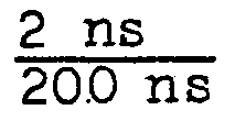
- FIG. 5 shows two oscillograms relating to the time base error f in nanoseconds (ns) as a function of the frequency f in Hertz (Hz).
- M denotes the error signal of the motor of the drive roller 6
- Ro denotes the respective error signal of the deflection roller 9, in the example in the embodiment of the hat roller 20.
- the time error of the motor M is approximately 200 ns.
- This measurement chart was an experimental arrangement with a free-running, braked deflecting roller 20 based on the runout of the roll / um was less than 4, which is moderately production very expensive.
- the measurement diagram 5 b was again recorded with the same deflection roller 20, which, however, was braked according to the invention, with the values of the example mentioned.
Landscapes
- Registering, Tensioning, Guiding Webs, And Rollers Therefor (AREA)
- Magnetic Record Carriers (AREA)
- Advancing Webs (AREA)
- Paints Or Removers (AREA)
Abstract
Description
- Die Erfindung betrifft eine Umlenkeinrichtung für einen bandförmigen Aufzeichnungsträger, insbesondere ein Magnetband, das in seiner Längsrichtung starken Beschleunigungen unterworfen wird, bei welcher wenigstens eine auf einer Lagervorrichtung drehbare Umlenkrolle vorgesehen ist, worüber das transportierte Band geführt ist.
- Eine derartige Umlenkeinrichtung soll insbesondere bei nach dem Kontaktwickel-Laufwerken arbeitenden Magnetbandgeräten (sogenannten Schnelläufern) einsetzbar sein. Bei portablen, kleinen Video-Aufzeichnungs-Geräten, bei denen jegliche Wartung vermieden werden soll, ist die Umlenkeinrichtung gemäß im folgenden zu beschreibender Erfindung besonders vorteilhaft anwendbar.
- In bekannten Rollenumlenkeinrichtungen für Magnetbänder bemüht man sich gewöhnlich, die Drehreibung der Rolle(n) gegenüber dem Lager niedrig zu halten und hinsichtlich des Band-Rollenflächenkontakts, die Flächen so aneinander anzupassen, daß Bandschlupf verhindert wird und die Rolle ständig mitgedreht wird.
- Ein Beispiel ist in der DE-AS 16 25 592 beschrieben, worin die Rolle mittels Kugellager praktisch reibungsfrei gelagert ist. Um die Längsschwingungen eines in seiner Längsrichtung einer starken Beschleunigung unterworfenen Magnetbandes zu dämpfen, ist es gemäß DE-PS 12 49 340 bekannt, die Führungsrolle mit Samt zu überziehen, wobei die Samthaare dem Magnetband zugewandt sein sollen. Die Länge der Haare liegt bei Halbzollband bei ca. 5 mm. Hinsichtlich Band-Rollenflächenkontakt ist diese Samtauflage nicht günstig, da Schlupf auftritt.
- Es ist mit der DE-PS 705 813 ferner für eine Tonfilmvorrichtung bekannt, vor der Tonrolle eine Bremsrolle für den Film vorzusehen, damit der Film auf der Tonrolle die erforderliche Spannung zur Mitnahme der Schwungmasse erhält, und somit das Auftreten von Schlupf vermieden wird.
- Mit der US-PS 3 593 945 ist ferner ein Magnetbandlaufwerk nach dem Kontaktwickelprinzip ("Schnelläufer") bekannt, in dem feststehende Führungszapfen benutzt werden. Das Band kommt dabei unvermeidbar in Kontakt mit der Führungsfläche und es treten Verschleiß und Störungen im Bandlauf auf.
- Es sind weiterhin stationäre Luftführungen für Magnetbandgeräte bekannt, wobei ein Luftpolster den Kontakt des Bandes mit der Führungsfläche weitgehend verhindert (z.B. FR-PS 1 197 820). Der Aufwand solcher Luftführungen ist beträchtlich groß.
- Die vorliegende Erfindung hat sich die Aufgabe gestellt, die Umlenkeinrichtungen, insbesondere für schnellaufende Magnetbandgeräte zu verbessern, um die Störsignale bei Aufnahme/Wiedergabe aufgezeichneter Signale zu reduzieren bei geringstmöglichem Aufwand.
- Diese Aufgabe wird überraschenderweise gelöst, wenn an der Umlenkeinrichtung gemäß Einleitung ein Hemmoment zwischen der Rolle und der Lagervorrichtung erzeugt wird, dessen Größe einer am Rollenumfang angreifenden Reibkraft zwischen 2 und 15 p, vorzugsweise zwischen 2 und 10 p entspricht.
- Dadurch wird funktionsmäßig erreicht, daß die Rolle oberhalb einer Mindest-Bandtransportgeschwindigkeit feststeht und sich im wesentlichen nur dreht, wenn infolge einer sehr glatten Ausbildung der Kontaktfläche zwischen Rolle und Band letzteres an dieser Fläche klebt, was als Slip-Stick-Effekt bekannt ist, oder, wenn die Mindestgeschwindigkeit des Bandes nicht erreicht wird. Der Effekt, daß die Rolle stehenbleibt beim Bandtransport wird erfindungsgemäß bewußt herbeigeführt, obwohl er bei allen bisher bekannten Magnetbandlaufwerken mit allen Mitteln, wie auch der oben zitierte Stand der Technik zeigt, vermieden wird.
- Da das Hemmoment durch einfache Bremsvorrichtungen erzeugbar und einstellbar ist, ist die erfindungsgemäße Lösung auch mit geringem Aufwand realisierbar. In jedem Fall kann ein Unrundlaufen der Rolle kompensiert werden. In weiterer Ausführung kann die Rolle mit einer Oberflächenrauhigkeit Ra von weniger als 0,5/um, insbesondere unter 0,28/um ausgebildet sein. Dadurch wird die Reibung der Luft an der Rollenfläche vermindert und die Erzeugung einer Grenzschicht zwischen Band und Rolle begünstigt.
- In weiterer Ausbildung kann die Umlenkrolle mit Höhenführungsflanschen versehen sein, die auch mit der Lagervorrichtung fest verbunden sein können. Diese Flansche können sich auch nur um einen Teil des Rollenumfangs erstrecken und Einlauf- und Auslaufanfasungen für das Band aufweisen.
- Dadurch wird die Bandbeanspruchung verringert bei Erhöhung der Höhenführung. In weiteren Ausführungen kann entweder eine einzige oder es können zwei Umlenkrollen vorgesehen sein, wobei der Magnetkopf jeweils zwischen Bandrolle und Umlenkrolle oder zwischen den Umlenkrollen anzuordnen ist.
- Die oben angedeutete Erzeugung einer.Grenzschicht hat die Voraussetzung, daß das Band mit hoher Geschwindigkeit über die Rolle transportiert wird und daß ein ausreichender Bandzug aufrechterhalten wird und Oberflächenrauhigkeiten unter 0,5/um auf der Rollenfläche vorhanden sind.
- Zwischen der Rollenfläche, wo die Luft die Geschwindigkeit Null besitzt, also daran haftet und dem Band, das annähernd eine reibungsfreieStrömungerzeugt, befindet sich eine dünne übergangsschicht - die sogenannte Grenz-oder Reibungsschicht, in welcher ein starker Geschwindigkeitsanstieg von Null bis zur Bandgeschwindigkeit stattfindet. Diese Schicht ist aufteilbar in einen Bereich mit annähernd reibungsfreier Bewegung und die Grenzschicht, in der wegen des großen Geschwindigkeitsgradientens trotz kleiner Zähigkeit der Luft erhebliche Reibungswirkungen ausgelöst werden. Für die Grenzschicht gelten die Navier-Stokeschen-Gleichungen vgl. auch W. Kauffmann, Technische Hydro- und Aerodynamik. Springer Verlag 1963, S. 233 bis 240, insbesondere die Prandtl'sche Grenzschichttheorie. über die Luftfilmlagerung beim Transport eines Bandes über eine Rolle s. W.A. Gross IBM Research Latoratory, San Jose, USA, insbesondere Seiten 138 bis 141.
- Es hat sich überraschenderweise in der Praxis herausgestellt, daß die Ausbildung der Grenzschicht am günstigsten ist, wenn die Rolle steht, weil dann die Reibkraft, die indirekt vom Band auf die Rolle ausgeübt wird, gerade kompensiert wird. Wird die zur Ausbildung der Grenzschicht notwendige Mindestgeschwindigkeit unterschritten, so wird infolge der Vergrößerung der auf die Rolle ausgeübten indirekten Reibkraft die Rolle mitge- dreht, wodurch Schlupf zwischen Rolle und Band vermieden wird.
- Einzelheiten des erfindungsgemäßen Verfahrens sind schematischen, in der Zeichnung dargestellten und im folgenden beschriebenen Ausführungsbeispielen zu entnehmen.
- In der Zeichnung ist dargestellt in
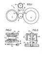
- Fig. 1 ein schematischer Kontaktwickel-Transport mit Bandumlenkrolle
- Fig. 2 eine Bandumlenkrolle mit Festflanschen und einer Wirbelstrom- oder Hysteresebremse
- Fig. 3 eine weitere Bandumlenkrolle mit intergrierten Flanschen und einer Blockbremse
- Fig. 4 ein Diagramm Reibkraft einer Blockbremse als Funktion der Bandgeschwindigkeit
- Fig. 5a Kurvendiagramme der Zeitbasisfehler über der und 5b Frequenz
- Ein Schnelläuferlaufwerk 5 besteht im wesentlichen aus der Antriebsrolle 6, die zwischen dem Aufwickel 7 und dem Abwickel 8 angeordnet ist und bei der an gegebenen Drehrichtung a) den Aufwickel in der Richtung b) und den Abwickel in der Richtung c) antreibt. Zwischen Aufwickel und Abwickel 7 bzw. 8 ist auf einer gemeinsamen Achse und in derselben Ebene mit der Antriebsrolle 6 eine Umlenkrolle 9 angeordnet, über deren Umfang das Band 10 geführt ist. Wie schematisch angedeutet, kann auf der freien Bandlänge zwischen Antriebs und Umlenkrolle 6 bzw. 9 mindestens ein Aufzeichnungs- und/oder Abtastkopf 11 angeordnet sein. Je nachdem wie das Band 10 auf dem Abwickel 8 aufgewickelt ist, ist der Kopf 11 innerhalb oder außerhalb der Bandschlaufe angeordnet. Im vorliegenden Fall, da die Folienseite des Bandes 10 auf den Wickeln nach innen gewickelt ist, ist der Kopf 11 innerhalb der Schlaufe vorgesehen.
- über einen elastisch verformbaren Umfangsrand an der Antriebsrolle 5 werden die mittels nicht dargestellter Andruckvorrichtungen an die Rolle 5 angedrückten - Auf- und Abwickel 7 bzw. 8 fast schlupflos angetrieben, wodurch ein Hochgeschwindigkeits-Bandtransport, insbesondere für dünne und sehr dünne Magnetbänder mit einer Gesamtdicke von 15/u oder 9/u oder darunter, erreichbar ist.
- Die Umlenkrolle 9 besitzt in jedem Falle Höhenführungsflansche 12 für das Band 10, die entweder als mitdrehende Flansche (Fig. 3) oder als feste Flansche (Fig. 2) ausgebildet sind.
- Es hat sich in der Praxis herausgestellt, daß bei ständig mitdrehender Rolle 9 das Band an einigen Stellen am Umfang ständig in Kontakt mit der Rollenfläche steht und ein Schleifvorgang stattfindet, der im Extremfall einer genügend glatten Rollenstelle ein Kleben des Bandes 10 bewirkt. Insbesondere bei ständigem Richtungswechsel des Bandtransports findet auch wechselnder Kontakt mit Stellen der Rollenfläche statt. Dadurch wird das. Band wechselnden Bandzügen unterworfen, was sich als Bandflutter, insbesondere bei Zeitbasisfehlermessungen bei Fernsehsignalaufzeichnungen bemerkbar macht.
- Erfindungsmäßig wurde überraschend festgestellt, daß bei definierter Bremsung der Rolle die Bandfluttereinflüsse verringerbar sind und bei Bremsung der Rolle zum Stillstand bei Bandlauf, der von der Rolle sonst erzeugte Zeitbasisfehler völlig eliminiert werden kann. Als Ursache dieser erheblichen Verbesserung wird die Erzeugung einer Grenzschicht angesehen, die den Bandtransport auf einer Luftschicht über die Rollenfläche ermöglicht. Ein Restreibwert nach Erzeugung der Grenzschicht wird als Hemmoment an der Rolle aufgebracht, um bei und oberhalb einer Mindestbandgeschwindigkeit, die etwa im Bereich von 2-4 m/s liegt, einen Rollenstillstand zu erreichen. Fällt diese Geschwindigkeit unter den Mindestwert ab z.B. beim Richtungswechsel oder beim Anfahren oder Auslaufen des Laufwerks, so dreht sich die Rolle wieder aufgrund der dann fehlenden Grenzschicht und des daraus resultierenden höheren Restreibwertes zwischen Band und Rolle. Der Restreibwert ist, wie aus den in der Einleitung genannten Literaturstellen hervorgeht, vom Bandzug abhängig, es ist daher zweckmäßig, das Hemmoment an der Umlenkrolle mittels einer einstellbaren Bremseinrichtung zu erzeugen. Verwendbare Bremseinrichtungen sind in den Figuren 2 und 3 dargestellt.
- Eine zylinderförmige Umlenkrolle 13 ist mit einer drehbar in Lagern 14 gelagerten Achse 15 fest verbunden. Die Lager 14 sind in Chassisteilen 16 des Laufwerks 5 vorgesehen. Mit den Teilen 16 sind ebenfalls Höhenführungsflansehe 17 fest verbunden, die zumindest im Umschlingungsbereich des Bandes 10 angeordnet sind. Mit dieser Kombination einer Drehrolle 13 mit Festflanschen 17-ist es bereits möglich, auftretende Scrapeflutter-Störungen des Laufwerks zu vermindern, vgl. z.B. DE-GM 78 20 877.
- Am unteren Ende der Achse 15 kann eine Metallscheibe 18 befestigt sein, die in den Luftspalt einer Dauermagnet-oder Elektromagneteinrichtung 19 heineinragt. Je nachdem, ob das Metall leitfähig oder magnetisch ist, wird damit , eine Wirbelstrombremse oder eine Hysteresebremse geschaffen, deren Bremskraft entweder bei einem Dauermagnet entsprechend fest oder bei einem Elektromagnet variabel einstellbar ist.
- In Figur 3 ist eine hutförmige Rolle 20 mit integrierten Flanschen 21 auf einer fest verbundenen Achse 22, die wiederum an Chassisteilen 16 drehbar gelagert ist, dargestellt. Eine Lagerstelle 23 befindet sich innerhalb der Rolle 20, die andere 24 außerhalb. Zwischen den Lagerstellen 23 und 24 ist eine durch Bremsblöcken und Schraube dargestellte Blockbremse 25 vorgesehen, womit eine definierte Bremskraft an der Achse 22 fest einstellbar ist.
- Die beschriebenen Bremsvorrichtungen 18 und 19 und 25 stehen für alle überhaupt verwendbaren Arten und Ausführungen solcher Vorrichtungen. Außer den beschriebenen Beispielen sind dem Fachmann beispielsweise noch folgende Arten von Bremsvorrichtungen bekannt: Freilaufbremsen, Scheibenbremsen, Lagerwiderstandsbremsen, Massenträgheitsbremsen, Viskositätsbremsen und Lamellenbremsen. Welche der Fachmann davon auswählt, hängt von den jeweiligen Gegebenheiten ab.
- In jedem Fall sollte die gewählte Bremse zur Erzeugung eines Hemmoments entsprechend einerReibkraft am Umfang der Rolle zwischen 2 und 15 p, vorzugsweise zwischen 2 und 10 p,geeignet sein. Bei einem Rollendurchmesser von 17,5 mm entsprechen die Reibkräfte einem Moment von ca. 0,18 . 10-3 Nm bis 1,35 Nm und vorzugsweise bis 0,9 . 10" Nm. In einem Bandtransport der schematisch beschriebenen Art sind beispielsweise die folgenden Werte gegeben:
- Durchmesser Umlenkrolle d = 17,5 mm Abstand der Höhenführungsflansche b = 8,05 mm bei 8 mm Bandbreite Umschlingungsbogen des Bandes c = 13,7 mm Bandgeschwindigkeit v = 4 m/s Mittenrauhigkeit der Rollenfläche 0,25 ,um , Bandzugkraft

- Der Verlauf der Reibkraft R in Abhängigkeit von der Bandgeschwindigkeit ist für die Bandzugkräfte B = 40 Pond und 60 Pond in Figur 4 schematisch dargestellt. Es wird deutlich, daß für eine Mindestgeschwindigkeit, bei der die Grenzschicht erzeugt wird, die Reibkraft deutlich abfällt, im vorliegenden Beispiel zwischen 2,5 und 3 m/s bzw. zwischen 3,5 und 4 m/s.
- In Figur 5 sind zwei Oszillogramme betreffend den Zeitbasisfehler f in Nanosecunden (ns) in Abhängigkeit von der Frequenz f in Hertz (Hz) dargestellt. Mit M ist das Fehlersignal des Motors der Antriebsrolle 6 und mit Ro das jeweilige Fehlersignal der Umlenkrolle 9, im Beispiel in der Ausführung der Hutrolle 20, bezeichnet.
- Im Meßdiagramm 5a beträgt der Zeitfehler des Motors M etwa 200 ns. Diesem Meßdiagramm lag eine Versuchsanordnung mit einer freilaufenden, ungebremsten Umlenkrolle 20 zugrunde, wobei die Unrundheit der Rolle weniger als 4 /um betrug, was herstellungsmäßig sehr aufwendig ist. Das Meßdiagramm 5 b wurde dagegen mit derselben Umlenkrolle 20, die jedoch erfindungsgemäß definiert gebremst war, wiederum mit den Werten des genannten Beispiels aufgenommen.
- Es ergab sich bei etwa unverändertem Fehlersignal M des Motors ein nicht mehr sichtbares Fehlersignal Ro, was einer Fehlersignalverbesserung von
Claims (9)
Priority Applications (1)
| Application Number | Priority Date | Filing Date | Title |
|---|---|---|---|
| AT81107455T ATE7635T1 (de) | 1980-10-27 | 1981-09-19 | Umlenkeinrichtung fuer einen bandfoermigen aufzeichnungstraeger, insbesondere fuer ein magnetband. |
Applications Claiming Priority (2)
| Application Number | Priority Date | Filing Date | Title |
|---|---|---|---|
| DE19808028597U DE8028597U1 (de) | 1980-10-27 | 1980-10-27 | Umlenkeinrichtung fuer einen bandfoermigen aufzeichnungstraeger, insbesondere fuer ein magnetband |
| DE8028597U | 1980-10-27 |
Publications (2)
| Publication Number | Publication Date |
|---|---|
| EP0050737A1 true EP0050737A1 (de) | 1982-05-05 |
| EP0050737B1 EP0050737B1 (de) | 1984-05-23 |
Family
ID=6720049
Family Applications (1)
| Application Number | Title | Priority Date | Filing Date |
|---|---|---|---|
| EP81107455A Expired EP0050737B1 (de) | 1980-10-27 | 1981-09-19 | Umlenkeinrichtung für einen bandförmigen Aufzeichnungsträger, insbesondere für ein Magnetband |
Country Status (5)
| Country | Link |
|---|---|
| US (1) | US4456160A (de) |
| EP (1) | EP0050737B1 (de) |
| JP (1) | JPS57100648A (de) |
| AT (1) | ATE7635T1 (de) |
| DE (2) | DE8028597U1 (de) |
Cited By (1)
| Publication number | Priority date | Publication date | Assignee | Title |
|---|---|---|---|---|
| EP0563640A1 (de) * | 1992-03-13 | 1993-10-06 | Sony Corporation | Führungsvorrichtung für ein magnetisches Band |
Families Citing this family (9)
| Publication number | Priority date | Publication date | Assignee | Title |
|---|---|---|---|---|
| JP2793410B2 (ja) * | 1991-04-22 | 1998-09-03 | インターナショナル・ビジネス・マシーンズ・コーポレイション | ウェブ駆動装置及びテープ駆動装置 |
| US5346155A (en) * | 1992-04-30 | 1994-09-13 | Minnesota Mining And Manufacturing Company | Belt driven cartridge with magnetic brake assembly |
| US5409174A (en) * | 1993-12-30 | 1995-04-25 | Xerox Corporation | High speed transport cassette |
| US5447278A (en) * | 1993-12-30 | 1995-09-05 | Xerox Corporation | Tape drive and cassette with precise registration |
| US6125096A (en) * | 1998-04-08 | 2000-09-26 | Stomage Technology Comporation | Dynamic/stationary tape guide |
| US6078481A (en) * | 1998-06-08 | 2000-06-20 | Imation Corp. | Tape storage cartridge having two-level tape path |
| WO2001061693A1 (en) * | 2000-02-18 | 2001-08-23 | Koninklijke Philips Electronics N.V. | Recording and/or reproducing apparatus including at least one guide arrangement having at least one damping projection |
| US6570740B1 (en) * | 2000-08-21 | 2003-05-27 | Hewlett-Packard Development Company, L.P. | Tape guide with wear resistant coating |
| US7255297B2 (en) | 2004-06-04 | 2007-08-14 | Quantum Corporation | Adaptive tape drive roller guide |
Citations (7)
| Publication number | Priority date | Publication date | Assignee | Title |
|---|---|---|---|---|
| DD85101A (de) * | ||||
| DE1295012B (de) * | 1964-09-09 | 1969-05-14 | Telefunken Patent | Fuehrung fuer bandfoermige Aufzeichnungstraeger |
| DE2125399A1 (de) * | 1971-05-21 | 1972-11-30 | Siemens Ag | Anordnung zum umkehrbaren Antrieb eines Bandes |
| DE2350816B2 (de) * | 1972-10-13 | 1977-05-12 | American Videonetics Corp., Sunnyvale, Calif. (V.StA.) | Bandtransporteinrichtung |
| US4110670A (en) * | 1976-05-20 | 1978-08-29 | Nippon Columbia Kabushikikaisha | Braking apparatus |
| DE2722509A1 (de) * | 1977-05-18 | 1978-11-23 | Basf Ag | Bandfuehrungseinrichtung fuer schnellaufende magnetbandgeraete |
| EP0007494A1 (de) * | 1978-07-12 | 1980-02-06 | BASF Aktiengesellschaft | Führungseinrichtung für einen dünnen bandförmigen Aufzeichnungsträger, insbesondere für ein Magnetband |
Family Cites Families (7)
| Publication number | Priority date | Publication date | Assignee | Title |
|---|---|---|---|---|
| US2724065A (en) * | 1951-03-30 | 1955-11-15 | Erwin J Saxl | Magnetic drag for control of yarn tension |
| US3122295A (en) * | 1962-06-04 | 1964-02-25 | Sylvania Electric Prod | Web transport |
| US3398870A (en) * | 1967-01-23 | 1968-08-27 | Ibm | Controlled air film bearing |
| US3534893A (en) * | 1968-04-18 | 1970-10-20 | Rca Corp | Device for generation of a self-acting fluid bearing |
| US3593945A (en) * | 1968-05-01 | 1971-07-20 | Mennesota Mining And Mfg Co | Capstan assembly |
| US3843035A (en) * | 1973-01-18 | 1974-10-22 | Basf Ag | Guide element for magnetic tapes |
| US3951356A (en) * | 1974-01-02 | 1976-04-20 | Borg-Warner Corporation | Tape transport |
-
1980
- 1980-10-27 DE DE19808028597U patent/DE8028597U1/de not_active Expired
-
1981
- 1981-09-19 AT AT81107455T patent/ATE7635T1/de not_active IP Right Cessation
- 1981-09-19 EP EP81107455A patent/EP0050737B1/de not_active Expired
- 1981-09-19 DE DE8181107455T patent/DE3163761D1/de not_active Expired
- 1981-10-16 US US06/312,320 patent/US4456160A/en not_active Expired - Fee Related
- 1981-10-21 JP JP56167321A patent/JPS57100648A/ja active Granted
Patent Citations (7)
| Publication number | Priority date | Publication date | Assignee | Title |
|---|---|---|---|---|
| DD85101A (de) * | ||||
| DE1295012B (de) * | 1964-09-09 | 1969-05-14 | Telefunken Patent | Fuehrung fuer bandfoermige Aufzeichnungstraeger |
| DE2125399A1 (de) * | 1971-05-21 | 1972-11-30 | Siemens Ag | Anordnung zum umkehrbaren Antrieb eines Bandes |
| DE2350816B2 (de) * | 1972-10-13 | 1977-05-12 | American Videonetics Corp., Sunnyvale, Calif. (V.StA.) | Bandtransporteinrichtung |
| US4110670A (en) * | 1976-05-20 | 1978-08-29 | Nippon Columbia Kabushikikaisha | Braking apparatus |
| DE2722509A1 (de) * | 1977-05-18 | 1978-11-23 | Basf Ag | Bandfuehrungseinrichtung fuer schnellaufende magnetbandgeraete |
| EP0007494A1 (de) * | 1978-07-12 | 1980-02-06 | BASF Aktiengesellschaft | Führungseinrichtung für einen dünnen bandförmigen Aufzeichnungsträger, insbesondere für ein Magnetband |
Cited By (1)
| Publication number | Priority date | Publication date | Assignee | Title |
|---|---|---|---|---|
| EP0563640A1 (de) * | 1992-03-13 | 1993-10-06 | Sony Corporation | Führungsvorrichtung für ein magnetisches Band |
Also Published As
| Publication number | Publication date |
|---|---|
| ATE7635T1 (de) | 1984-06-15 |
| JPS57100648A (en) | 1982-06-22 |
| US4456160A (en) | 1984-06-26 |
| DE8028597U1 (de) | 1981-02-19 |
| EP0050737B1 (de) | 1984-05-23 |
| DE3163761D1 (en) | 1984-06-28 |
| JPS647419B2 (de) | 1989-02-08 |
Similar Documents
| Publication | Publication Date | Title |
|---|---|---|
| DE3882224T2 (de) | Gleitkörper für einen magnetkopf. | |
| EP0050737B1 (de) | Umlenkeinrichtung für einen bandförmigen Aufzeichnungsträger, insbesondere für ein Magnetband | |
| DE3103874A1 (de) | Verfahren und vorrichtung zum bearbeiten der oberflaeche magnetischer aufzeichnungstraeger | |
| DE2341364A1 (de) | Bandantriebssystem | |
| DE2053762C2 (de) | Bandtransporteinrichtung | |
| EP0007494A1 (de) | Führungseinrichtung für einen dünnen bandförmigen Aufzeichnungsträger, insbesondere für ein Magnetband | |
| DE2313007A1 (de) | Kassettenrekorder | |
| DE2436008A1 (de) | Laufwerk fuer magnetbandgeraete | |
| DE1123124B (de) | Antriebsvorrichtung fuer den Aufzeichnungstraeger eines Magnetbandgeraets | |
| DE19915530A1 (de) | Dynamisch-stationäre Bandführung | |
| DE702345C (de) | Antriebsvorrichtung fuer Geraete zur magnetischen Schallaufzeichnung | |
| DE4447031C2 (de) | Wickeleinrichtung für bandförmige Aufzeichnungsträger | |
| DD153264A5 (de) | Magnetbandkassette und magnetbandgeraet | |
| DE2209584C3 (de) | Anordnung zum flatterfreien Führen eines Magnetbandes im Bereich eines Magnetkopfes | |
| DE2140303A1 (de) | ||
| DE845109C (de) | Geraet zur Tonaufnahme und -wiedergabe | |
| DE912870C (de) | Vorrichtung zum Umspulen von Draehten oder Baendern, insbesondere fuer Geraete zur magnetischen Schallaufzeichnung und Schallwiedergabe | |
| DE1905325C3 (de) | Bandtransporteinrichtung | |
| DE623070C (de) | Antriebsvorrichtung fuer bandfoermige Aufzeichnungstraeger in Tonfilmapparaturen | |
| EP0039423B1 (de) | Bandlaufwerk nach dem Kontaktwickelprinzip | |
| DE3245036A1 (de) | Bandantrieb | |
| DE2800313A1 (de) | Endlosband-transportvorrichtung | |
| DE1499617C3 (de) | Umsteuerbare Bandantriebsvorrichtung | |
| DE1499803C3 (de) | Bandtransportvorrichtung | |
| AT200823B (de) |
Legal Events
| Date | Code | Title | Description |
|---|---|---|---|
| PUAI | Public reference made under article 153(3) epc to a published international application that has entered the european phase |
Free format text: ORIGINAL CODE: 0009012 |
|
| 17P | Request for examination filed |
Effective date: 19811022 |
|
| AK | Designated contracting states |
Designated state(s): AT BE CH DE FR GB NL SE |
|
| GRAA | (expected) grant |
Free format text: ORIGINAL CODE: 0009210 |
|
| AK | Designated contracting states |
Designated state(s): AT BE CH DE FR GB LI NL SE |
|
| PG25 | Lapsed in a contracting state [announced via postgrant information from national office to epo] |
Ref country code: SE Effective date: 19840523 Ref country code: BE Effective date: 19840523 |
|
| REF | Corresponds to: |
Ref document number: 7635 Country of ref document: AT Date of ref document: 19840615 Kind code of ref document: T |
|
| REF | Corresponds to: |
Ref document number: 3163761 Country of ref document: DE Date of ref document: 19840628 |
|
| PG25 | Lapsed in a contracting state [announced via postgrant information from national office to epo] |
Ref country code: AT Effective date: 19840919 |
|
| ET | Fr: translation filed | ||
| PG25 | Lapsed in a contracting state [announced via postgrant information from national office to epo] |
Ref country code: LI Effective date: 19840930 Ref country code: CH Effective date: 19840930 |
|
| PLBE | No opposition filed within time limit |
Free format text: ORIGINAL CODE: 0009261 |
|
| STAA | Information on the status of an ep patent application or granted ep patent |
Free format text: STATUS: NO OPPOSITION FILED WITHIN TIME LIMIT |
|
| REG | Reference to a national code |
Ref country code: CH Ref legal event code: PL |
|
| 26N | No opposition filed | ||
| PGFP | Annual fee paid to national office [announced via postgrant information from national office to epo] |
Ref country code: NL Payment date: 19920930 Year of fee payment: 12 |
|
| PGFP | Annual fee paid to national office [announced via postgrant information from national office to epo] |
Ref country code: FR Payment date: 19930804 Year of fee payment: 13 |
|
| PGFP | Annual fee paid to national office [announced via postgrant information from national office to epo] |
Ref country code: GB Payment date: 19930916 Year of fee payment: 13 |
|
| PGFP | Annual fee paid to national office [announced via postgrant information from national office to epo] |
Ref country code: DE Payment date: 19930920 Year of fee payment: 13 |
|
| PG25 | Lapsed in a contracting state [announced via postgrant information from national office to epo] |
Ref country code: NL Effective date: 19940401 |
|
| NLV4 | Nl: lapsed or anulled due to non-payment of the annual fee | ||
| PG25 | Lapsed in a contracting state [announced via postgrant information from national office to epo] |
Ref country code: GB Effective date: 19940919 |
|
| GBPC | Gb: european patent ceased through non-payment of renewal fee |
Effective date: 19940919 |
|
| PG25 | Lapsed in a contracting state [announced via postgrant information from national office to epo] |
Ref country code: FR Effective date: 19950531 |
|
| PG25 | Lapsed in a contracting state [announced via postgrant information from national office to epo] |
Ref country code: DE Effective date: 19950601 |
|
| REG | Reference to a national code |
Ref country code: FR Ref legal event code: ST |