EP0050737A1 - Dispositif de renvoi pour un support d'enregistrement, en particulier pour une bande magnétique - Google Patents
Dispositif de renvoi pour un support d'enregistrement, en particulier pour une bande magnétique Download PDFInfo
- Publication number
- EP0050737A1 EP0050737A1 EP81107455A EP81107455A EP0050737A1 EP 0050737 A1 EP0050737 A1 EP 0050737A1 EP 81107455 A EP81107455 A EP 81107455A EP 81107455 A EP81107455 A EP 81107455A EP 0050737 A1 EP0050737 A1 EP 0050737A1
- Authority
- EP
- European Patent Office
- Prior art keywords
- roller
- tape
- deflection
- belt
- roll
- Prior art date
- Legal status (The legal status is an assumption and is not a legal conclusion. Google has not performed a legal analysis and makes no representation as to the accuracy of the status listed.)
- Granted
Links
- 230000002401 inhibitory effect Effects 0.000 claims description 7
- 230000001133 acceleration Effects 0.000 claims description 3
- 230000002093 peripheral effect Effects 0.000 abstract description 2
- 238000004804 winding Methods 0.000 description 5
- 238000005259 measurement Methods 0.000 description 4
- 238000010586 diagram Methods 0.000 description 3
- 230000000694 effects Effects 0.000 description 3
- 230000015572 biosynthetic process Effects 0.000 description 2
- 230000002349 favourable effect Effects 0.000 description 2
- 210000004209 hair Anatomy 0.000 description 2
- 238000004519 manufacturing process Methods 0.000 description 2
- 239000002184 metal Substances 0.000 description 2
- 238000000034 method Methods 0.000 description 2
- 230000003746 surface roughness Effects 0.000 description 2
- 238000012423 maintenance Methods 0.000 description 1
- 230000007257 malfunction Effects 0.000 description 1
- 238000011160 research Methods 0.000 description 1
- 230000007704 transition Effects 0.000 description 1
- 230000001960 triggered effect Effects 0.000 description 1
Images

Classifications
-
- G—PHYSICS
- G11—INFORMATION STORAGE
- G11B—INFORMATION STORAGE BASED ON RELATIVE MOVEMENT BETWEEN RECORD CARRIER AND TRANSDUCER
- G11B15/00—Driving, starting or stopping record carriers of filamentary or web form; Driving both such record carriers and heads; Guiding such record carriers or containers therefor; Control thereof; Control of operating function
- G11B15/18—Driving; Starting; Stopping; Arrangements for control or regulation thereof
- G11B15/22—Stopping means
-
- G—PHYSICS
- G11—INFORMATION STORAGE
- G11B—INFORMATION STORAGE BASED ON RELATIVE MOVEMENT BETWEEN RECORD CARRIER AND TRANSDUCER
- G11B15/00—Driving, starting or stopping record carriers of filamentary or web form; Driving both such record carriers and heads; Guiding such record carriers or containers therefor; Control thereof; Control of operating function
- G11B15/18—Driving; Starting; Stopping; Arrangements for control or regulation thereof
- G11B15/26—Driving record carriers by members acting directly or indirectly thereon
- G11B15/28—Driving record carriers by members acting directly or indirectly thereon through rollers driving by frictional contact with the record carrier, e.g. capstan; Multiple arrangements of capstans or drums coupled to means for controlling the speed of the drive; Multiple capstan systems alternately engageable with record carrier to provide reversal
- G11B15/295—Driving record carriers by members acting directly or indirectly thereon through rollers driving by frictional contact with the record carrier, e.g. capstan; Multiple arrangements of capstans or drums coupled to means for controlling the speed of the drive; Multiple capstan systems alternately engageable with record carrier to provide reversal with single capstan or drum simultaneously driving the record carrier at two separate points of an isolated part thereof, e.g. the capstan acting directly on the tape rollers
-
- G—PHYSICS
- G11—INFORMATION STORAGE
- G11B—INFORMATION STORAGE BASED ON RELATIVE MOVEMENT BETWEEN RECORD CARRIER AND TRANSDUCER
- G11B15/00—Driving, starting or stopping record carriers of filamentary or web form; Driving both such record carriers and heads; Guiding such record carriers or containers therefor; Control thereof; Control of operating function
- G11B15/60—Guiding record carrier
- G11B15/605—Guiding record carrier without displacing the guiding means
Definitions
- the invention relates to a deflection device for a tape-shaped recording medium, in particular a magnetic tape which is subjected to strong accelerations in its longitudinal direction, in which at least one deflection roller rotatable on a bearing device is provided, over which the transported tape is guided.
- Such a deflection device is said to be usable in particular in magnetic tape devices (so-called high-speed drives) working after the contact winding drives.
- the deflection device according to the invention to be described below can be used particularly advantageously.
- DE-PS 705 813 It is also known from DE-PS 705 813 for a sound film device to provide a brake roller for the film in front of the sound reel, so that the film on the sound reel receives the required tension for carrying the flywheel mass, and thus the occurrence of slippage is avoided.
- US Pat. No. 3,593,945 also discloses a magnetic tape drive based on the contact winding principle ("high-speed runner") in which fixed guide pins are used. The tape inevitably comes into contact with the guide surface and wear and malfunctions occur in the tape run.
- the object of the present invention is to improve the deflection devices, in particular for high-speed magnetic tape devices, in order to reduce the interference signals during recording / playback of recorded signals with the least possible effort.
- This object is surprisingly achieved when an inhibiting torque between the roller and the bearing device is generated on the deflection device according to the introduction, the size of which corresponds to a frictional force acting on the roller circumference of between 2 and 15 p, preferably between 2 and 10 p.
- the roll is fixed above a minimum tape transport speed and essentially only rotates if the latter sticks to this surface as a result of a very smooth formation of the contact surface between the roll and tape, which is known as a slip-stick effect, or if the minimum speed of the belt is not reached.
- the effect that the roll stops during tape transport is consciously brought about according to the invention, although it is avoided by all means in all previously known magnetic tape drives, as the prior art cited above shows.
- the solution according to the invention can also be implemented with little effort.
- roll runout can be compensated.
- the roller can be designed with a surface roughness Ra of less than 0.5 / ⁇ m, in particular less than 0.28 / ⁇ m. This reduces the friction of the air on the roller surface and favors the creation of an interface between the belt and the roller.
- the deflection roller can be provided with height guide flanges, which can also be firmly connected to the bearing device. These flanges can also extend only around a part of the circumference of the roller and have inlet and outlet chamfers for the belt.
- either a single or two deflection rollers can be provided, the magnetic head being between each Belt roll and pulley or between the pulleys is to be arranged.
- the formation of the boundary layer is most favorable when the roller is stationary, because then the frictional force which is indirectly exerted on the roller by the belt is just being compensated. If the speed required to form the boundary layer is undershot, the role is also increased due to the increase in the indirect frictional force exerted on the role. rotates, which prevents slippage between the roll and belt.
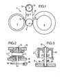
- a high-speed drive 5 consists essentially of the drive roller 6, which is arranged between the reel 7 and the unwind 8 and in the given direction of rotation a) drives the reel in the direction b) and the unwind in the direction c).
- a deflection roller 9 is arranged on a common axis and in the same plane with the drive roller 6, over the circumference of which the belt 10 is guided.
- at least one recording and / or scanning can be carried out on the free tape length between the drive and the deflection roller 6 or 9 head 11 may be arranged.
- the head 11 is arranged inside or outside the band loop. In the present case, since the film side of the band 10 is wound inwards on the windings, the head 11 is provided within the loop.
- the up and unwinding 7 and 8 which are pressed onto the roller 5 by means of pressure devices (not shown), are driven almost without slippage, as a result of which high-speed tape transport, in particular for thin and very thin magnetic tapes with a total thickness of 15 / u or 9 / u or below, is achievable.
- the deflection roller 9 has in each case height guide flanges 12 for the band 10, which are either designed as rotating flanges (Fig. 3) or as fixed flanges (Fig. 2).
- the belt flutter influences can be reduced when the roll is braked in a defined manner and when the roll is braked to a stop stood for tape run, the time base errors otherwise generated by the reel can be completely eliminated.
- the cause of this considerable improvement is considered to be the creation of a boundary layer which enables the tape to be transported on an air layer over the roller surface.
- a residual coefficient of friction after the boundary layer has been generated is applied as an inhibiting moment on the roll in order to achieve a roll standstill at and above a minimum belt speed which is approximately in the range of 2-4 m / s.
- a cylindrical deflection roller 13 is fixedly connected to an axis 15 rotatably mounted in bearings 14.
- the bearings 14 are provided in chassis parts 16 of the drive 5.
- height guide flange 17 are also firmly connected, which are arranged at least in the wrapping area of the belt 10.
- a metal disk 18 can be attached, which protrudes into the air gap of a permanent magnet or electromagnet device 19.
- a metal disk 18 can be attached, which protrudes into the air gap of a permanent magnet or electromagnet device 19.
- an eddy current brake or a hysteresis brake is created, the braking force of which is either fixed accordingly with a permanent magnet or variably adjustable with an electromagnet.
- FIG. 3 shows a hat-shaped roller 20 with integrated flanges 21 on a permanently connected axle 22, which in turn is rotatably mounted on chassis parts 16.
- One bearing 23 is inside the roller 20, the other 24 outside.
- the braking devices 18 and 19 and 25 described stand for all types and designs of such devices that can be used at all.
- the following types of brake devices are known to the person skilled in the art: free-wheel brakes, disc brakes, bearing resistance brakes, inertia brakes, viscosity brakes and multi-disk brakes. Which one the specialist chooses depends on the particular circumstances.
- the selected brake should be suitable for generating an inhibiting torque corresponding to a frictional force on the circumference of the roller between 2 and 15 p, preferably between 2 and 10 p.
- the friction forces correspond to a moment of approx. 0.18. 10-3 Nm to 1.35 Nm and preferably up to 0.9. 10 "Nm.
- the following values are given, for example, in a belt conveyor of the type described schematically:
- FIG. 5 shows two oscillograms relating to the time base error f in nanoseconds (ns) as a function of the frequency f in Hertz (Hz).
- M denotes the error signal of the motor of the drive roller 6
- Ro denotes the respective error signal of the deflection roller 9, in the example in the embodiment of the hat roller 20.
- the time error of the motor M is approximately 200 ns.
- This measurement chart was an experimental arrangement with a free-running, braked deflecting roller 20 based on the runout of the roll / um was less than 4, which is moderately production very expensive.
- the measurement diagram 5 b was again recorded with the same deflection roller 20, which, however, was braked according to the invention, with the values of the example mentioned.
Landscapes
- Registering, Tensioning, Guiding Webs, And Rollers Therefor (AREA)
- Magnetic Record Carriers (AREA)
- Advancing Webs (AREA)
- Paints Or Removers (AREA)
Priority Applications (1)
| Application Number | Priority Date | Filing Date | Title |
|---|---|---|---|
| AT81107455T ATE7635T1 (de) | 1980-10-27 | 1981-09-19 | Umlenkeinrichtung fuer einen bandfoermigen aufzeichnungstraeger, insbesondere fuer ein magnetband. |
Applications Claiming Priority (2)
| Application Number | Priority Date | Filing Date | Title |
|---|---|---|---|
| DE19808028597U DE8028597U1 (de) | 1980-10-27 | 1980-10-27 | Umlenkeinrichtung fuer einen bandfoermigen aufzeichnungstraeger, insbesondere fuer ein magnetband |
| DE8028597U | 1980-10-27 |
Publications (2)
| Publication Number | Publication Date |
|---|---|
| EP0050737A1 true EP0050737A1 (fr) | 1982-05-05 |
| EP0050737B1 EP0050737B1 (fr) | 1984-05-23 |
Family
ID=6720049
Family Applications (1)
| Application Number | Title | Priority Date | Filing Date |
|---|---|---|---|
| EP81107455A Expired EP0050737B1 (fr) | 1980-10-27 | 1981-09-19 | Dispositif de renvoi pour un support d'enregistrement, en particulier pour une bande magnétique |
Country Status (5)
| Country | Link |
|---|---|
| US (1) | US4456160A (fr) |
| EP (1) | EP0050737B1 (fr) |
| JP (1) | JPS57100648A (fr) |
| AT (1) | ATE7635T1 (fr) |
| DE (2) | DE8028597U1 (fr) |
Cited By (1)
| Publication number | Priority date | Publication date | Assignee | Title |
|---|---|---|---|---|
| EP0563640A1 (fr) * | 1992-03-13 | 1993-10-06 | Sony Corporation | Dispositif de guidage pour une bande magnétique |
Families Citing this family (9)
| Publication number | Priority date | Publication date | Assignee | Title |
|---|---|---|---|---|
| JP2793410B2 (ja) * | 1991-04-22 | 1998-09-03 | インターナショナル・ビジネス・マシーンズ・コーポレイション | ウェブ駆動装置及びテープ駆動装置 |
| US5346155A (en) * | 1992-04-30 | 1994-09-13 | Minnesota Mining And Manufacturing Company | Belt driven cartridge with magnetic brake assembly |
| US5409174A (en) * | 1993-12-30 | 1995-04-25 | Xerox Corporation | High speed transport cassette |
| US5447278A (en) * | 1993-12-30 | 1995-09-05 | Xerox Corporation | Tape drive and cassette with precise registration |
| US6125096A (en) * | 1998-04-08 | 2000-09-26 | Stomage Technology Comporation | Dynamic/stationary tape guide |
| US6078481A (en) * | 1998-06-08 | 2000-06-20 | Imation Corp. | Tape storage cartridge having two-level tape path |
| WO2001061693A1 (fr) * | 2000-02-18 | 2001-08-23 | Koninklijke Philips Electronics N.V. | Appareil d'enregistrement et/ou de reproduction comprenant au moins un systeme de guidage avec au moins une projection d'amortissement |
| US6570740B1 (en) * | 2000-08-21 | 2003-05-27 | Hewlett-Packard Development Company, L.P. | Tape guide with wear resistant coating |
| US7255297B2 (en) | 2004-06-04 | 2007-08-14 | Quantum Corporation | Adaptive tape drive roller guide |
Citations (7)
| Publication number | Priority date | Publication date | Assignee | Title |
|---|---|---|---|---|
| DD85101A (fr) * | ||||
| DE1295012B (de) * | 1964-09-09 | 1969-05-14 | Telefunken Patent | Fuehrung fuer bandfoermige Aufzeichnungstraeger |
| DE2125399A1 (de) * | 1971-05-21 | 1972-11-30 | Siemens Ag | Anordnung zum umkehrbaren Antrieb eines Bandes |
| DE2350816B2 (de) * | 1972-10-13 | 1977-05-12 | American Videonetics Corp., Sunnyvale, Calif. (V.StA.) | Bandtransporteinrichtung |
| US4110670A (en) * | 1976-05-20 | 1978-08-29 | Nippon Columbia Kabushikikaisha | Braking apparatus |
| DE2722509A1 (de) * | 1977-05-18 | 1978-11-23 | Basf Ag | Bandfuehrungseinrichtung fuer schnellaufende magnetbandgeraete |
| EP0007494A1 (fr) * | 1978-07-12 | 1980-02-06 | BASF Aktiengesellschaft | Dispositif de guidage d'une bande d'enregistrement, en particulier d'une bande magnétique |
Family Cites Families (7)
| Publication number | Priority date | Publication date | Assignee | Title |
|---|---|---|---|---|
| US2724065A (en) * | 1951-03-30 | 1955-11-15 | Erwin J Saxl | Magnetic drag for control of yarn tension |
| US3122295A (en) * | 1962-06-04 | 1964-02-25 | Sylvania Electric Prod | Web transport |
| US3398870A (en) * | 1967-01-23 | 1968-08-27 | Ibm | Controlled air film bearing |
| US3534893A (en) * | 1968-04-18 | 1970-10-20 | Rca Corp | Device for generation of a self-acting fluid bearing |
| US3593945A (en) * | 1968-05-01 | 1971-07-20 | Mennesota Mining And Mfg Co | Capstan assembly |
| US3843035A (en) * | 1973-01-18 | 1974-10-22 | Basf Ag | Guide element for magnetic tapes |
| US3951356A (en) * | 1974-01-02 | 1976-04-20 | Borg-Warner Corporation | Tape transport |
-
1980
- 1980-10-27 DE DE19808028597U patent/DE8028597U1/de not_active Expired
-
1981
- 1981-09-19 AT AT81107455T patent/ATE7635T1/de not_active IP Right Cessation
- 1981-09-19 EP EP81107455A patent/EP0050737B1/fr not_active Expired
- 1981-09-19 DE DE8181107455T patent/DE3163761D1/de not_active Expired
- 1981-10-16 US US06/312,320 patent/US4456160A/en not_active Expired - Fee Related
- 1981-10-21 JP JP56167321A patent/JPS57100648A/ja active Granted
Patent Citations (7)
| Publication number | Priority date | Publication date | Assignee | Title |
|---|---|---|---|---|
| DD85101A (fr) * | ||||
| DE1295012B (de) * | 1964-09-09 | 1969-05-14 | Telefunken Patent | Fuehrung fuer bandfoermige Aufzeichnungstraeger |
| DE2125399A1 (de) * | 1971-05-21 | 1972-11-30 | Siemens Ag | Anordnung zum umkehrbaren Antrieb eines Bandes |
| DE2350816B2 (de) * | 1972-10-13 | 1977-05-12 | American Videonetics Corp., Sunnyvale, Calif. (V.StA.) | Bandtransporteinrichtung |
| US4110670A (en) * | 1976-05-20 | 1978-08-29 | Nippon Columbia Kabushikikaisha | Braking apparatus |
| DE2722509A1 (de) * | 1977-05-18 | 1978-11-23 | Basf Ag | Bandfuehrungseinrichtung fuer schnellaufende magnetbandgeraete |
| EP0007494A1 (fr) * | 1978-07-12 | 1980-02-06 | BASF Aktiengesellschaft | Dispositif de guidage d'une bande d'enregistrement, en particulier d'une bande magnétique |
Cited By (1)
| Publication number | Priority date | Publication date | Assignee | Title |
|---|---|---|---|---|
| EP0563640A1 (fr) * | 1992-03-13 | 1993-10-06 | Sony Corporation | Dispositif de guidage pour une bande magnétique |
Also Published As
| Publication number | Publication date |
|---|---|
| ATE7635T1 (de) | 1984-06-15 |
| JPS57100648A (en) | 1982-06-22 |
| US4456160A (en) | 1984-06-26 |
| DE8028597U1 (de) | 1981-02-19 |
| EP0050737B1 (fr) | 1984-05-23 |
| DE3163761D1 (en) | 1984-06-28 |
| JPS647419B2 (fr) | 1989-02-08 |
Similar Documents
| Publication | Publication Date | Title |
|---|---|---|
| DE3882224T2 (de) | Gleitkörper für einen magnetkopf. | |
| EP0050737B1 (fr) | Dispositif de renvoi pour un support d'enregistrement, en particulier pour une bande magnétique | |
| DE3103874A1 (de) | Verfahren und vorrichtung zum bearbeiten der oberflaeche magnetischer aufzeichnungstraeger | |
| DE2341364A1 (de) | Bandantriebssystem | |
| DE2053762C2 (de) | Bandtransporteinrichtung | |
| EP0007494A1 (fr) | Dispositif de guidage d'une bande d'enregistrement, en particulier d'une bande magnétique | |
| DE2313007A1 (de) | Kassettenrekorder | |
| DE2436008A1 (de) | Laufwerk fuer magnetbandgeraete | |
| DE1123124B (de) | Antriebsvorrichtung fuer den Aufzeichnungstraeger eines Magnetbandgeraets | |
| DE19915530A1 (de) | Dynamisch-stationäre Bandführung | |
| DE702345C (de) | Antriebsvorrichtung fuer Geraete zur magnetischen Schallaufzeichnung | |
| DE4447031C2 (de) | Wickeleinrichtung für bandförmige Aufzeichnungsträger | |
| DD153264A5 (de) | Magnetbandkassette und magnetbandgeraet | |
| DE2209584C3 (de) | Anordnung zum flatterfreien Führen eines Magnetbandes im Bereich eines Magnetkopfes | |
| DE2140303A1 (fr) | ||
| DE845109C (de) | Geraet zur Tonaufnahme und -wiedergabe | |
| DE912870C (de) | Vorrichtung zum Umspulen von Draehten oder Baendern, insbesondere fuer Geraete zur magnetischen Schallaufzeichnung und Schallwiedergabe | |
| DE1905325C3 (de) | Bandtransporteinrichtung | |
| DE623070C (de) | Antriebsvorrichtung fuer bandfoermige Aufzeichnungstraeger in Tonfilmapparaturen | |
| EP0039423B1 (fr) | Dispositif transporteur de bande basé sur le principe du contact par enroulement | |
| DE3245036A1 (de) | Bandantrieb | |
| DE2800313A1 (de) | Endlosband-transportvorrichtung | |
| DE1499617C3 (de) | Umsteuerbare Bandantriebsvorrichtung | |
| DE1499803C3 (de) | Bandtransportvorrichtung | |
| AT200823B (fr) |
Legal Events
| Date | Code | Title | Description |
|---|---|---|---|
| PUAI | Public reference made under article 153(3) epc to a published international application that has entered the european phase |
Free format text: ORIGINAL CODE: 0009012 |
|
| 17P | Request for examination filed |
Effective date: 19811022 |
|
| AK | Designated contracting states |
Designated state(s): AT BE CH DE FR GB NL SE |
|
| GRAA | (expected) grant |
Free format text: ORIGINAL CODE: 0009210 |
|
| AK | Designated contracting states |
Designated state(s): AT BE CH DE FR GB LI NL SE |
|
| PG25 | Lapsed in a contracting state [announced via postgrant information from national office to epo] |
Ref country code: SE Effective date: 19840523 Ref country code: BE Effective date: 19840523 |
|
| REF | Corresponds to: |
Ref document number: 7635 Country of ref document: AT Date of ref document: 19840615 Kind code of ref document: T |
|
| REF | Corresponds to: |
Ref document number: 3163761 Country of ref document: DE Date of ref document: 19840628 |
|
| PG25 | Lapsed in a contracting state [announced via postgrant information from national office to epo] |
Ref country code: AT Effective date: 19840919 |
|
| ET | Fr: translation filed | ||
| PG25 | Lapsed in a contracting state [announced via postgrant information from national office to epo] |
Ref country code: LI Effective date: 19840930 Ref country code: CH Effective date: 19840930 |
|
| PLBE | No opposition filed within time limit |
Free format text: ORIGINAL CODE: 0009261 |
|
| STAA | Information on the status of an ep patent application or granted ep patent |
Free format text: STATUS: NO OPPOSITION FILED WITHIN TIME LIMIT |
|
| REG | Reference to a national code |
Ref country code: CH Ref legal event code: PL |
|
| 26N | No opposition filed | ||
| PGFP | Annual fee paid to national office [announced via postgrant information from national office to epo] |
Ref country code: NL Payment date: 19920930 Year of fee payment: 12 |
|
| PGFP | Annual fee paid to national office [announced via postgrant information from national office to epo] |
Ref country code: FR Payment date: 19930804 Year of fee payment: 13 |
|
| PGFP | Annual fee paid to national office [announced via postgrant information from national office to epo] |
Ref country code: GB Payment date: 19930916 Year of fee payment: 13 |
|
| PGFP | Annual fee paid to national office [announced via postgrant information from national office to epo] |
Ref country code: DE Payment date: 19930920 Year of fee payment: 13 |
|
| PG25 | Lapsed in a contracting state [announced via postgrant information from national office to epo] |
Ref country code: NL Effective date: 19940401 |
|
| NLV4 | Nl: lapsed or anulled due to non-payment of the annual fee | ||
| PG25 | Lapsed in a contracting state [announced via postgrant information from national office to epo] |
Ref country code: GB Effective date: 19940919 |
|
| GBPC | Gb: european patent ceased through non-payment of renewal fee |
Effective date: 19940919 |
|
| PG25 | Lapsed in a contracting state [announced via postgrant information from national office to epo] |
Ref country code: FR Effective date: 19950531 |
|
| PG25 | Lapsed in a contracting state [announced via postgrant information from national office to epo] |
Ref country code: DE Effective date: 19950601 |
|
| REG | Reference to a national code |
Ref country code: FR Ref legal event code: ST |