EP0046919B1 - Verfahren und Vorrichtung zur kontinuierlichen Filterung von Flüssigkeiten - Google Patents
Verfahren und Vorrichtung zur kontinuierlichen Filterung von Flüssigkeiten Download PDFInfo
- Publication number
- EP0046919B1 EP0046919B1 EP81106369A EP81106369A EP0046919B1 EP 0046919 B1 EP0046919 B1 EP 0046919B1 EP 81106369 A EP81106369 A EP 81106369A EP 81106369 A EP81106369 A EP 81106369A EP 0046919 B1 EP0046919 B1 EP 0046919B1
- Authority
- EP
- European Patent Office
- Prior art keywords
- filter
- liquid
- candle
- cock
- bypass
- Prior art date
- Legal status (The legal status is an assumption and is not a legal conclusion. Google has not performed a legal analysis and makes no representation as to the accuracy of the status listed.)
- Expired
Links
- 239000007788 liquid Substances 0.000 title claims description 66
- 238000000034 method Methods 0.000 title claims description 12
- 238000001914 filtration Methods 0.000 title claims description 5
- 238000007872 degassing Methods 0.000 claims description 13
- 238000013022 venting Methods 0.000 claims description 8
- 230000035508 accumulation Effects 0.000 claims description 2
- 238000009825 accumulation Methods 0.000 claims description 2
- 238000004590 computer program Methods 0.000 claims description 2
- 235000009508 confectionery Nutrition 0.000 claims 1
- 238000004519 manufacturing process Methods 0.000 description 13
- 238000000576 coating method Methods 0.000 description 3
- 239000012459 cleaning agent Substances 0.000 description 2
- 239000000839 emulsion Substances 0.000 description 2
- 238000002360 preparation method Methods 0.000 description 2
- 230000001174 ascending effect Effects 0.000 description 1
- 238000004140 cleaning Methods 0.000 description 1
- 239000011248 coating agent Substances 0.000 description 1
- 238000010276 construction Methods 0.000 description 1
- 238000012423 maintenance Methods 0.000 description 1
- 239000000463 material Substances 0.000 description 1
- 229920000642 polymer Polymers 0.000 description 1
- 239000011148 porous material Substances 0.000 description 1
- 230000000630 rising effect Effects 0.000 description 1
- 238000009423 ventilation Methods 0.000 description 1
Images


Classifications
-
- B—PERFORMING OPERATIONS; TRANSPORTING
- B01—PHYSICAL OR CHEMICAL PROCESSES OR APPARATUS IN GENERAL
- B01D—SEPARATION
- B01D36/00—Filter circuits or combinations of filters with other separating devices
- B01D36/001—Filters in combination with devices for the removal of gas, air purge systems
-
- B—PERFORMING OPERATIONS; TRANSPORTING
- B01—PHYSICAL OR CHEMICAL PROCESSES OR APPARATUS IN GENERAL
- B01D—SEPARATION
- B01D35/00—Filtering devices having features not specifically covered by groups B01D24/00 - B01D33/00, or for applications not specifically covered by groups B01D24/00 - B01D33/00; Auxiliary devices for filtration; Filter housing constructions
- B01D35/12—Devices for taking out of action one or more units of multi- unit filters, e.g. for regeneration
Definitions
- the invention relates to a method and an apparatus for the continuous filtering of liquids with two candle filters and switching devices for the optional use of one or the other candle filter and a by-pass for venting and filling the candle filter before the respective start-up.
- candle filters depth filters
- production must be interrupted to change the filter cartridges. This leads to considerable losses in material and downtimes of the expensive production machines to reduce the machine return.
- a filter system is known from a brochure (Fujiplate Polymer Filter, Fuji Filter MFG. Co. Ltd. Japan) which has two filter units A and B connected in parallel. While filter A is in operation, filter B can be emptied and cleaned.
- the outlet valve is provided with a bypass through which the cleaning agents are introduced into the filter against the direction of flow.
- the inlet valve is provided with a bypass through which the cleaning agent flows out.
- the filter unit consists of a housing with two filters and a valve device, in which one or two valve bodies with a large number of bores are rotatably mounted in order to selectively supply the liquid to one or the other filter and at the same time to empty and then drain the filter that is out of operation vent and refill its cleaning.
- This double filter system requires due to its or their complicated designed valve body and the valve housing a considerable effort in the manufacture and maintenance and accordingly causes high costs. Due to the arrangement of the filters below the valve and the construction of the valve body, the interior of the double filter system cannot be completely vented, so that air residues are trapped, from which air bubbles are entrained uncontrollably during production.
- the invention has for its object to find a method and a device of the type mentioned, with which it is easily possible to continuously filter liquids without air inclusions or bubbles get into the filtered liquid and that a second filter when switching ready for use with a filtered liquid from the same batch.
- the device for carrying out the method is advantageously characterized in that the candle filters I and 11 are arranged close to one another and are connected to one another for the liquid inlet with a first two-way valve on the liquid inlet sides and for the liquid outlet to the consumer with a three-way valve on the filter outlet sides in that a bypass valve is provided which connects the filter outlet sides for a partial flow of the liquid to one another and allows the candle filters to be emptied, and that the candle filters I and II are each provided with a nozzle through which a constant small partial flow of the liquid can be fed to a degassing device.
- This double filter unit is advantageously characterized by a very compact, space-saving design.
- the inlets and outlets, the switching taps and the filter housing are integrated in such a way that there are no dead spaces for possible air pockets or accumulations. Due to the arrangement and design of the switching taps, the switching operations are reduced to a minimum and allow the filters to be flushed from the inside with filtered liquid in a simple manner.
- the filter in the supply can be constantly vented and flushed with a partial flow of the liquid and thus immediately deliver filtered liquid from the same batch when used.
- the bypass is provided with an aperture, the aperture being sharp-edged and therefore largely independent of viscosity.
- the bypass operation of the filter which is in standby mode enables an immediate switchover from filter I to filter 11 (or vice versa) without disturbing the production.
- the switched off filter can be emptied, disassembled, cleaned and vented during ongoing production.
- Commercial filter cartridges can also be used.
- a Fil t er Touch can vary depending on the pressure difference on the filter, indicating the degree of soiling, or after a predetermined scheme, or manually controlled by a computer program, are performed.
- the switching taps are provided with drives, such as solenoids or servomotors.
- a filter unit consisting of two candle filters I and 11, in which the filter 11 is in operation while the filter I is in preparation.
- the product a liquid 5
- a liquid 5 is conveyed through a rising pipe with a pump to a first tap 1, a two-way tap.
- the tap 1 the liquid flows from the outside on the filter inlet side 25 into the filter chamber 24, penetrates the filter body 23 and the filter tube 22 and thus reaches the interior 21 on the filter outlet side 26 and on the side A of a second tap 2, a three-way tap.
- the filtered liquid at C tap 2 and reaches a consumer 6 in an ascending pipeline.
- any air or gas bubbles present in the liquid to be filtered do not penetrate into the filter body 23 with a suitable pore size, but collect on the surface thereof, unite and rise in the upper part of the filter.
- the filters are provided at the top with nozzles 10, 20 through which a small part of the liquid flows continuously and entrains gas or air bubbles.
- the connectors 10, 20 are connected via a line to a degassing system, not shown, in which the liquid is degassed and returned to production.
- Another tap 3 a bypass tap, is arranged under the second tap.
- a partial flow of the filtered liquid flows via the bypass ED on the filter outlet side 16 to the filter I, flows through the filter body 13 from the interior 11 1 and the inner tube 12, reaches the exterior 14 of the filter I and leaves the filter through the nozzle 10.
- This measure ensures that the filter is always filled with the batch of liquid to be filtered that has just been produced and can thus be switched immediately to the filter inlet side 15 of the filter I when the filter 11 has to be cleaned. Any air bubbles are removed from the filter by the partial flow.
- Taps 1 to 3 can be manually switched individually according to a scheme for commissioning, operation and filter change.
- the taps 1 to 3 can, depending on the pressure difference at the filter, be provided with actuating means, such as actuating magnets or actuating motors, which are controlled by a computer (not shown).
- the bypass valve 3 has a throttle or orifice 4 with which the partial flow is influenced by the bypass.
- the diaphragm 4 is provided with a sharp edge, so that an equally large partial flow is obtained over a wide range even for liquids with different viscosities.
- the bypass valve serves to empty the filters I and 11 in their positions DF and EF, the liquid flowing out through the outlet 8. The filter can thus be emptied, disassembled, cleaned, vented and made available again during production.
- Figure 2 shows the position of the taps 1 to 3 when the filter device is started up.
- the liquid to be filtered flows from 5 to the inlet of the tap 1 at A and leaves the tap 1 at B, flows through the filter 11 from the outside and vents it through the nozzle 20, and passes filtered to the tap 2 at A, leaves the tap 2 at B and flows through the filter I from the inside, vents the interior 11, the filter tube 12, the filter body 13 and the filter exterior 14 and flows out of the air through the nozzle 10 to a downstream degassing system.
- FIG. 3 shows a production position of the taps 1 to 3 of the filters I and 11, in which the filter I works and the filter 11 is provided.
- the liquid 5 to be filtered flows through the tap 1 from A to C, the filter I in the reverse direction from the outside inwards and reaches a consumer 6 via the three-way tap 2 from B to C.
- a small partial flow of the liquid filtered by the filter I flows through the bypass valve 3 on the way DE and then the filter II from the inside to the outside and leaves the available filter 11 through the nozzle 20. While the filter I is working, the filter 11 is thus constantly supplied with already filtered liquid and kept ready for switching.
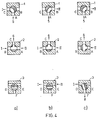
- FIG. 4 shows the switching steps for a filter change from filter I to filter II.
- the tap 2 is first switched so that both filters I and II can deliver filtered liquid to the consumer 6. Valves 1 and 3 remain unchanged in this switching step.
- the tap 1 is switched so that the liquid to be filtered flows in at A and flows to filter 11 at B.
- Figure 4c shows the position of the taps after the third step. While the liquid to be filtered flows through the tap 1 via AB to the filter II, the tap 2 is switched so that the liquid filtered by the filter II in the tap 2 reaches the consumer 6 via the path AC.
- the bypass valve 3 is now switched so that the liquid in the filter I can flow out into a line 8 via the path DF. While the filter 11 is working, the filter I can be cleaned. The filter change is finished. Switching to filter 1 is carried out in an analogous manner.
Landscapes
- Chemical & Material Sciences (AREA)
- Chemical Kinetics & Catalysis (AREA)
- Filtration Of Liquid (AREA)
Applications Claiming Priority (2)
| Application Number | Priority Date | Filing Date | Title |
|---|---|---|---|
| DE19803032690 DE3032690A1 (de) | 1980-08-29 | 1980-08-29 | Verfahren und vorrichtung zur kontinuierlichen filterung von fluessigkeiten |
| DE3032690 | 1980-08-29 |
Publications (2)
| Publication Number | Publication Date |
|---|---|
| EP0046919A1 EP0046919A1 (de) | 1982-03-10 |
| EP0046919B1 true EP0046919B1 (de) | 1983-07-27 |
Family
ID=6110724
Family Applications (1)
| Application Number | Title | Priority Date | Filing Date |
|---|---|---|---|
| EP81106369A Expired EP0046919B1 (de) | 1980-08-29 | 1981-08-17 | Verfahren und Vorrichtung zur kontinuierlichen Filterung von Flüssigkeiten |
Country Status (4)
| Country | Link |
|---|---|
| US (1) | US4341642A (cg-RX-API-DMAC7.html) |
| EP (1) | EP0046919B1 (cg-RX-API-DMAC7.html) |
| JP (1) | JPS5771612A (cg-RX-API-DMAC7.html) |
| DE (2) | DE3032690A1 (cg-RX-API-DMAC7.html) |
Cited By (1)
| Publication number | Priority date | Publication date | Assignee | Title |
|---|---|---|---|---|
| CN104703670A (zh) * | 2012-10-04 | 2015-06-10 | 伊顿公司 | 伺服控制的反冲洗过滤器系统 |
Families Citing this family (19)
| Publication number | Priority date | Publication date | Assignee | Title |
|---|---|---|---|---|
| GB2124920B (en) * | 1982-07-20 | 1986-06-11 | Fluidtech Gmbh | A filtering device |
| DE3227059C2 (de) * | 1982-07-20 | 1995-03-30 | Fluidtech Gmbh | Filtervorrichtung |
| US4708790A (en) * | 1984-06-04 | 1987-11-24 | Champion International Corporation | Ultrafiltration system with regeneration control |
| DE3744422C1 (de) * | 1987-12-29 | 1989-07-06 | Du Pont Deutschland | Verfahren und Vorrichtung zur Entgasung und Filtration von Fluessigkeiten |
| DE3832679A1 (de) * | 1988-09-27 | 1990-03-29 | Boll & Kirch Filter | Rueckspuelfilter |
| US5015398A (en) * | 1989-05-09 | 1991-05-14 | Eastman Kodak Company | Method and apparatus for filtration of photographic emulsions |
| DE4015443A1 (de) * | 1990-01-24 | 1991-07-25 | Schiele Maschinenbau Gmbh | Einrichtung zum filtern eines fliess- oder stroemungsfaehigen stoffes |
| DE19604335C1 (de) * | 1996-02-07 | 1997-04-24 | Roetelmann Gmbh & Co | Vorrichtung zum Filtern von Flüssigkeiten |
| FI2692U1 (fi) * | 1996-09-05 | 1996-12-27 | Ari Laakko | Sihti |
| US5753111A (en) * | 1996-09-30 | 1998-05-19 | Eastman Kodak Company | Photographic processor and improved filter assembly |
| FI107127B (fi) | 1999-11-11 | 2001-06-15 | Parker Hannifin Oy | Menetelmä ja laitteisto nesteen suodattamiseksi |
| FI108000B (fi) * | 1999-11-11 | 2001-11-15 | Parker Hannifin Oy | Suodatuslaitteisto |
| DE10325525B4 (de) | 2003-06-04 | 2013-10-24 | Boll & Kirch Filterbau Gmbh | Rückspülfilter |
| DE102004004120B3 (de) * | 2004-01-26 | 2005-08-18 | Schröder Maschinenbau KG | Filteranlage für Flüssigkeiten |
| DE102005008923A1 (de) * | 2005-02-24 | 2006-09-14 | Mann + Hummel Gmbh | Ventilmodul |
| GB0714021D0 (en) * | 2007-07-18 | 2007-08-29 | Green Metals Ltd | Improvements in anode materials |
| TWI517895B (zh) * | 2010-03-01 | 2016-01-21 | Fujimi Inc | Method of filtration without degassing |
| US9439537B2 (en) * | 2011-10-10 | 2016-09-13 | Gary Haddock | Fully automated, twin-chamber, continuous hot oil filtration system |
| DE102017009990A1 (de) * | 2017-10-26 | 2019-05-02 | Hydac Process Technology Gmbh | Filtervorrichtung |
Family Cites Families (10)
| Publication number | Priority date | Publication date | Assignee | Title |
|---|---|---|---|---|
| NL132958C (cg-RX-API-DMAC7.html) * | 1945-04-07 | 1900-01-01 | ||
| US3056499A (en) * | 1958-09-26 | 1962-10-02 | Yarrow And Company | Filtration of liquids |
| US3618781A (en) * | 1969-08-22 | 1971-11-09 | Parker Hannifin Corp | Duplex filtering device |
| US3833121A (en) * | 1971-09-02 | 1974-09-03 | Brunswick Corp | Plastic filtration systems |
| US3815746A (en) * | 1972-02-18 | 1974-06-11 | Caterpillar Tractor Co | Air bleed liquid filter assembly |
| US3940222A (en) * | 1973-01-23 | 1976-02-24 | J. Zink Co., Inc. | Filter changing valve unit |
| US3915866A (en) * | 1973-10-11 | 1975-10-28 | Parker Hannifin Corp | High pressure filtering device |
| US3979232A (en) * | 1975-02-28 | 1976-09-07 | Honeywell Inc. | Mercury cadmium telluride annealing procedure |
| US4039305A (en) * | 1976-11-17 | 1977-08-02 | Caterpillar Tractor Co. | Apparatus for removing gas from a liquid system |
| CH622710A5 (cg-RX-API-DMAC7.html) * | 1977-11-12 | 1981-04-30 | Filtrox Maschinenbau Ag |
-
1980
- 1980-08-29 DE DE19803032690 patent/DE3032690A1/de not_active Withdrawn
-
1981
- 1981-08-17 DE DE8181106369T patent/DE3160707D1/de not_active Expired
- 1981-08-17 EP EP81106369A patent/EP0046919B1/de not_active Expired
- 1981-08-24 US US06/295,809 patent/US4341642A/en not_active Expired - Fee Related
- 1981-08-26 JP JP56132656A patent/JPS5771612A/ja active Granted
Cited By (1)
| Publication number | Priority date | Publication date | Assignee | Title |
|---|---|---|---|---|
| CN104703670A (zh) * | 2012-10-04 | 2015-06-10 | 伊顿公司 | 伺服控制的反冲洗过滤器系统 |
Also Published As
| Publication number | Publication date |
|---|---|
| EP0046919A1 (de) | 1982-03-10 |
| DE3160707D1 (en) | 1983-09-01 |
| US4341642A (en) | 1982-07-27 |
| JPH0117729B2 (cg-RX-API-DMAC7.html) | 1989-03-31 |
| JPS5771612A (en) | 1982-05-04 |
| DE3032690A1 (de) | 1982-05-06 |
Similar Documents
| Publication | Publication Date | Title |
|---|---|---|
| EP0046919B1 (de) | Verfahren und Vorrichtung zur kontinuierlichen Filterung von Flüssigkeiten | |
| DE69104367T2 (de) | Ausgabeverfahren und -vorrichtung, insbesondere für dichtungs-/klebemittel. | |
| DE3028528C2 (de) | Automatische Umschaltvorrichtung für ein Flüssigkeitsabgabesystem mit zwei Sätzen zusammenfaltbarer Beutel | |
| DE2701658C2 (de) | Automatische Umschaltvorrichtung für Anlagen zur Abgabe von zähflüssigen Flüssigkeiten | |
| DE3841198C2 (cg-RX-API-DMAC7.html) | ||
| EP0355632B1 (de) | Verfahren zum Aufbereiten der Bearbeitungsflüssigkeit einer Elektroerosionsmaschine | |
| DE10231096B4 (de) | Filtervorrichtung und Innenbehälter für eine Filtervorrichtung | |
| DE69920976T2 (de) | Verbesserte Abgabeventilmontageanordnung | |
| DE3213554A1 (de) | Fluessigkeits-zuteilungsvorrichtung | |
| DE2005548A1 (cg-RX-API-DMAC7.html) | ||
| EP0699462B1 (de) | Einrichtung zum Trennen von Flüssigkeiten unterschiedlicher Dichte | |
| DE2028929A1 (de) | Durchflußsteuerung zum Zufuhren von Flussigkeitsproben | |
| EP0054082A1 (de) | Vorrichtung zur Wasserreinigung | |
| DE2501733B2 (de) | Verfahren zur Ermittlung der Umschaltpunkte für Mischflüssigkeiten bei Filtrationsprozessen | |
| DE2245487B2 (de) | Verfahren und Anordnung zur Probeentnahme von Milch | |
| DE1236960C2 (de) | Vorrichtung zur uebernahme von milch | |
| DE3135813C2 (de) | Filtriervorrichtung zur Serien-Doppelfeinfiltration von Flüssigkeiten, insbesondere Dieselmotor-Schmieröl | |
| DE1582980C2 (de) | Vorrichtung zum Foerdern von Milch aus Kannen in einen Sammeltank | |
| DE2821384B2 (de) | Membranefilterapparat mit mindestens einer schlauchförmigen Membran | |
| DE3011339C2 (de) | Verfahren zur Reinigung der Röhren eines Kraftwerkskondensators und Einrichtung zur Durchführung des Verfahrens | |
| DE102004010968B4 (de) | Vorrichtung zum Filtrieren eines Fluids, insbesondere eines verflüssigten Kunststoffes | |
| DE3019987C2 (de) | Wirkdruckzumischgerät | |
| DE2353484C3 (de) | Durchlauffilter zur Entnahme gefilterter Flüssigkeit aus einer verunreinigten Flüssigkeit | |
| DE1967210C2 (de) | Wasseraufbereitungsanlage | |
| DE102004004121A1 (de) | Lakebehälter mit Filtersystem |
Legal Events
| Date | Code | Title | Description |
|---|---|---|---|
| PUAI | Public reference made under article 153(3) epc to a published international application that has entered the european phase |
Free format text: ORIGINAL CODE: 0009012 |
|
| 17P | Request for examination filed |
Effective date: 19810817 |
|
| AK | Designated contracting states |
Designated state(s): DE FR GB |
|
| RBV | Designated contracting states (corrected) |
Designated state(s): DE FR GB |
|
| GRAA | (expected) grant |
Free format text: ORIGINAL CODE: 0009210 |
|
| AK | Designated contracting states |
Designated state(s): DE FR GB |
|
| REF | Corresponds to: |
Ref document number: 3160707 Country of ref document: DE Date of ref document: 19830901 |
|
| ET | Fr: translation filed | ||
| PLBE | No opposition filed within time limit |
Free format text: ORIGINAL CODE: 0009261 |
|
| STAA | Information on the status of an ep patent application or granted ep patent |
Free format text: STATUS: NO OPPOSITION FILED WITHIN TIME LIMIT |
|
| 26N | No opposition filed | ||
| PGFP | Annual fee paid to national office [announced via postgrant information from national office to epo] |
Ref country code: DE Payment date: 19910725 Year of fee payment: 11 |
|
| PGFP | Annual fee paid to national office [announced via postgrant information from national office to epo] |
Ref country code: GB Payment date: 19910805 Year of fee payment: 11 Ref country code: FR Payment date: 19910805 Year of fee payment: 11 |
|
| PG25 | Lapsed in a contracting state [announced via postgrant information from national office to epo] |
Ref country code: GB Effective date: 19920817 |
|
| GBPC | Gb: european patent ceased through non-payment of renewal fee |
Effective date: 19920817 |
|
| PG25 | Lapsed in a contracting state [announced via postgrant information from national office to epo] |
Ref country code: FR Effective date: 19930430 |
|
| PG25 | Lapsed in a contracting state [announced via postgrant information from national office to epo] |
Ref country code: DE Effective date: 19930501 |
|
| REG | Reference to a national code |
Ref country code: FR Ref legal event code: ST |