EP0046919B1 - Process and apparatus for the continuous filtration of liquids - Google Patents
Process and apparatus for the continuous filtration of liquids Download PDFInfo
- Publication number
- EP0046919B1 EP0046919B1 EP81106369A EP81106369A EP0046919B1 EP 0046919 B1 EP0046919 B1 EP 0046919B1 EP 81106369 A EP81106369 A EP 81106369A EP 81106369 A EP81106369 A EP 81106369A EP 0046919 B1 EP0046919 B1 EP 0046919B1
- Authority
- EP
- European Patent Office
- Prior art keywords
- filter
- liquid
- candle
- cock
- bypass
- Prior art date
- Legal status (The legal status is an assumption and is not a legal conclusion. Google has not performed a legal analysis and makes no representation as to the accuracy of the status listed.)
- Expired
Links
- 239000007788 liquid Substances 0.000 title claims description 66
- 238000000034 method Methods 0.000 title claims description 12
- 238000001914 filtration Methods 0.000 title claims description 5
- 238000007872 degassing Methods 0.000 claims description 13
- 238000013022 venting Methods 0.000 claims description 8
- 230000035508 accumulation Effects 0.000 claims description 2
- 238000009825 accumulation Methods 0.000 claims description 2
- 238000004590 computer program Methods 0.000 claims description 2
- 235000009508 confectionery Nutrition 0.000 claims 1
- 238000004519 manufacturing process Methods 0.000 description 13
- 238000000576 coating method Methods 0.000 description 3
- 239000012459 cleaning agent Substances 0.000 description 2
- 239000000839 emulsion Substances 0.000 description 2
- 238000002360 preparation method Methods 0.000 description 2
- 230000001174 ascending effect Effects 0.000 description 1
- 238000004140 cleaning Methods 0.000 description 1
- 239000011248 coating agent Substances 0.000 description 1
- 238000010276 construction Methods 0.000 description 1
- 238000012423 maintenance Methods 0.000 description 1
- 239000000463 material Substances 0.000 description 1
- 229920000642 polymer Polymers 0.000 description 1
- 239000011148 porous material Substances 0.000 description 1
- 230000000630 rising effect Effects 0.000 description 1
- 238000009423 ventilation Methods 0.000 description 1
Images


Classifications
-
- B—PERFORMING OPERATIONS; TRANSPORTING
- B01—PHYSICAL OR CHEMICAL PROCESSES OR APPARATUS IN GENERAL
- B01D—SEPARATION
- B01D36/00—Filter circuits or combinations of filters with other separating devices
- B01D36/001—Filters in combination with devices for the removal of gas, air purge systems
-
- B—PERFORMING OPERATIONS; TRANSPORTING
- B01—PHYSICAL OR CHEMICAL PROCESSES OR APPARATUS IN GENERAL
- B01D—SEPARATION
- B01D35/00—Filtering devices having features not specifically covered by groups B01D24/00 - B01D33/00, or for applications not specifically covered by groups B01D24/00 - B01D33/00; Auxiliary devices for filtration; Filter housing constructions
- B01D35/12—Devices for taking out of action one or more units of multi- unit filters, e.g. for regeneration
Definitions
- the invention relates to a method and an apparatus for the continuous filtering of liquids with two candle filters and switching devices for the optional use of one or the other candle filter and a by-pass for venting and filling the candle filter before the respective start-up.
- candle filters depth filters
- production must be interrupted to change the filter cartridges. This leads to considerable losses in material and downtimes of the expensive production machines to reduce the machine return.
- a filter system is known from a brochure (Fujiplate Polymer Filter, Fuji Filter MFG. Co. Ltd. Japan) which has two filter units A and B connected in parallel. While filter A is in operation, filter B can be emptied and cleaned.
- the outlet valve is provided with a bypass through which the cleaning agents are introduced into the filter against the direction of flow.
- the inlet valve is provided with a bypass through which the cleaning agent flows out.
- the filter unit consists of a housing with two filters and a valve device, in which one or two valve bodies with a large number of bores are rotatably mounted in order to selectively supply the liquid to one or the other filter and at the same time to empty and then drain the filter that is out of operation vent and refill its cleaning.
- This double filter system requires due to its or their complicated designed valve body and the valve housing a considerable effort in the manufacture and maintenance and accordingly causes high costs. Due to the arrangement of the filters below the valve and the construction of the valve body, the interior of the double filter system cannot be completely vented, so that air residues are trapped, from which air bubbles are entrained uncontrollably during production.
- the invention has for its object to find a method and a device of the type mentioned, with which it is easily possible to continuously filter liquids without air inclusions or bubbles get into the filtered liquid and that a second filter when switching ready for use with a filtered liquid from the same batch.
- the device for carrying out the method is advantageously characterized in that the candle filters I and 11 are arranged close to one another and are connected to one another for the liquid inlet with a first two-way valve on the liquid inlet sides and for the liquid outlet to the consumer with a three-way valve on the filter outlet sides in that a bypass valve is provided which connects the filter outlet sides for a partial flow of the liquid to one another and allows the candle filters to be emptied, and that the candle filters I and II are each provided with a nozzle through which a constant small partial flow of the liquid can be fed to a degassing device.
- This double filter unit is advantageously characterized by a very compact, space-saving design.
- the inlets and outlets, the switching taps and the filter housing are integrated in such a way that there are no dead spaces for possible air pockets or accumulations. Due to the arrangement and design of the switching taps, the switching operations are reduced to a minimum and allow the filters to be flushed from the inside with filtered liquid in a simple manner.
- the filter in the supply can be constantly vented and flushed with a partial flow of the liquid and thus immediately deliver filtered liquid from the same batch when used.
- the bypass is provided with an aperture, the aperture being sharp-edged and therefore largely independent of viscosity.
- the bypass operation of the filter which is in standby mode enables an immediate switchover from filter I to filter 11 (or vice versa) without disturbing the production.
- the switched off filter can be emptied, disassembled, cleaned and vented during ongoing production.
- Commercial filter cartridges can also be used.
- a Fil t er Touch can vary depending on the pressure difference on the filter, indicating the degree of soiling, or after a predetermined scheme, or manually controlled by a computer program, are performed.
- the switching taps are provided with drives, such as solenoids or servomotors.
- a filter unit consisting of two candle filters I and 11, in which the filter 11 is in operation while the filter I is in preparation.
- the product a liquid 5
- a liquid 5 is conveyed through a rising pipe with a pump to a first tap 1, a two-way tap.
- the tap 1 the liquid flows from the outside on the filter inlet side 25 into the filter chamber 24, penetrates the filter body 23 and the filter tube 22 and thus reaches the interior 21 on the filter outlet side 26 and on the side A of a second tap 2, a three-way tap.
- the filtered liquid at C tap 2 and reaches a consumer 6 in an ascending pipeline.
- any air or gas bubbles present in the liquid to be filtered do not penetrate into the filter body 23 with a suitable pore size, but collect on the surface thereof, unite and rise in the upper part of the filter.
- the filters are provided at the top with nozzles 10, 20 through which a small part of the liquid flows continuously and entrains gas or air bubbles.
- the connectors 10, 20 are connected via a line to a degassing system, not shown, in which the liquid is degassed and returned to production.
- Another tap 3 a bypass tap, is arranged under the second tap.
- a partial flow of the filtered liquid flows via the bypass ED on the filter outlet side 16 to the filter I, flows through the filter body 13 from the interior 11 1 and the inner tube 12, reaches the exterior 14 of the filter I and leaves the filter through the nozzle 10.
- This measure ensures that the filter is always filled with the batch of liquid to be filtered that has just been produced and can thus be switched immediately to the filter inlet side 15 of the filter I when the filter 11 has to be cleaned. Any air bubbles are removed from the filter by the partial flow.
- Taps 1 to 3 can be manually switched individually according to a scheme for commissioning, operation and filter change.
- the taps 1 to 3 can, depending on the pressure difference at the filter, be provided with actuating means, such as actuating magnets or actuating motors, which are controlled by a computer (not shown).
- the bypass valve 3 has a throttle or orifice 4 with which the partial flow is influenced by the bypass.
- the diaphragm 4 is provided with a sharp edge, so that an equally large partial flow is obtained over a wide range even for liquids with different viscosities.
- the bypass valve serves to empty the filters I and 11 in their positions DF and EF, the liquid flowing out through the outlet 8. The filter can thus be emptied, disassembled, cleaned, vented and made available again during production.
- Figure 2 shows the position of the taps 1 to 3 when the filter device is started up.
- the liquid to be filtered flows from 5 to the inlet of the tap 1 at A and leaves the tap 1 at B, flows through the filter 11 from the outside and vents it through the nozzle 20, and passes filtered to the tap 2 at A, leaves the tap 2 at B and flows through the filter I from the inside, vents the interior 11, the filter tube 12, the filter body 13 and the filter exterior 14 and flows out of the air through the nozzle 10 to a downstream degassing system.
- FIG. 3 shows a production position of the taps 1 to 3 of the filters I and 11, in which the filter I works and the filter 11 is provided.
- the liquid 5 to be filtered flows through the tap 1 from A to C, the filter I in the reverse direction from the outside inwards and reaches a consumer 6 via the three-way tap 2 from B to C.
- a small partial flow of the liquid filtered by the filter I flows through the bypass valve 3 on the way DE and then the filter II from the inside to the outside and leaves the available filter 11 through the nozzle 20. While the filter I is working, the filter 11 is thus constantly supplied with already filtered liquid and kept ready for switching.
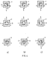
- FIG. 4 shows the switching steps for a filter change from filter I to filter II.
- the tap 2 is first switched so that both filters I and II can deliver filtered liquid to the consumer 6. Valves 1 and 3 remain unchanged in this switching step.
- the tap 1 is switched so that the liquid to be filtered flows in at A and flows to filter 11 at B.
- Figure 4c shows the position of the taps after the third step. While the liquid to be filtered flows through the tap 1 via AB to the filter II, the tap 2 is switched so that the liquid filtered by the filter II in the tap 2 reaches the consumer 6 via the path AC.
- the bypass valve 3 is now switched so that the liquid in the filter I can flow out into a line 8 via the path DF. While the filter 11 is working, the filter I can be cleaned. The filter change is finished. Switching to filter 1 is carried out in an analogous manner.
Description
Die Erfindung betrifft ein Verfahren und eine Vorrichtung zur kontinuierlichen Filterung von Flüssigkeiten mit zwei Kerzenfiltern und Umschalteinrichtungen zur wahlweisen Benutzung des einen oder anderen Kerzenfilters und einem Beiweg zur Entlüftung und Füllung der Kerzenfilter vor der jeweiligen Inbetriebnahme.The invention relates to a method and an apparatus for the continuous filtering of liquids with two candle filters and switching devices for the optional use of one or the other candle filter and a by-pass for venting and filling the candle filter before the respective start-up.
Für die kontinuierliche Filterung von Flüssigkeiten, z. B. von photographischen Emulsionen, werden Kerzenfilter (Tiefenfilter) eingesetzt. Bei Produktionszeiten, die die Stehzeiten der Filter überschreiten, muß zum Wechsel der Filterkerzen die Produktion unterbrochen werden. Dies führt zu erheblichen Verlusten an Material und durch Stillstandzeiten der teueren Produktionsmaschinen zur Minderung des Maschinenrendiments.For the continuous filtering of liquids, e.g. B. photographic emulsions, candle filters (depth filters) are used. In the event of production times that exceed the standing times of the filters, production must be interrupted to change the filter cartridges. This leads to considerable losses in material and downtimes of the expensive production machines to reduce the machine return.
Es sind automatisch oder manuell umschaltbare Doppelfilteranlagen bekannt, die einen beträchtlichen apparativen Aufwand und dementsprechend hohe Investitionskosten notwendig machen. Außerdem haben alle bekannten Systeme den Nachteil, daß die Innenräume der Filterkerzen beim Füllen nicht vollständig entlüftet werden können; dadurch wird die eingeschlossene Luft über eine längere Betriebszeit unkontrolliert über den Produktstrom in Form von Bläschen mitgeführt. Da z. B. in der photographischen Industrie bei der Beschichtung von Unterlagen die aufgetragene, photographische Emulsion absolut bläschenfrei sein muß, ist am Anfang des Beschichtungsvorganges oder bei einem Filterwechsel eine längere, nicht genau definierbare Zeit zur Entlüftung des Filters notwendig. Dieser Umstand führt zur Verringerung der Kapazitätsauslastung, insbesondere bei häufigem Produktwechsel. Außerdem kann nicht ausgeschlossen werden, daß noch Restbläschen während der schon begonnenen Beschichtung frei werden, die dann die beschichtete Ware unbrauchbar machen.Automatically or manually switchable double filter systems are known, which require a considerable amount of equipment and correspondingly high investment costs. In addition, all known systems have the disadvantage that the interior of the filter candles can not be completely vented when filling; As a result, the trapped air is carried in an uncontrolled manner in the form of bubbles over a longer operating time. Because e.g. B. in the photographic industry when coating documents, the photographic emulsion must be absolutely free of bubbles, a longer, not exactly definable time is necessary to vent the filter at the beginning of the coating process or when changing the filter. This leads to a reduction in capacity utilization, especially in the event of frequent product changes. In addition, it cannot be ruled out that residual bubbles will be released during the coating process that has already started, which then render the coated goods unusable.
Aus einem Prospekt (Fujiplate Polymer Filter, Fuji Filter MFG. Co. Ltd. Japan) ist ein Filtersystem bekannt, welches zwei parallel geschaltete Filtereinheiten A und B besitzt. Während der Filter A in Betrieb ist, kann der Filter B entleert und gereinigt werden. Hierzu ist das Auslaßventil mit einem Bypass versehen, durch den die Reinigungsmittel in den Filter gegen die Durchströmungsrichtung eingebracht werden. Das Einlaßventil ist mit einem Bypass versehen, durch den das Reinigungsmittel ausströmt. Dieses Filtersystem hat den Nachteil, daß eine ausreichende Entlüftung der Filter und Filtergehäuse nicht durchgeführt werden kann.A filter system is known from a brochure (Fujiplate Polymer Filter, Fuji Filter MFG. Co. Ltd. Japan) which has two filter units A and B connected in parallel. While filter A is in operation, filter B can be emptied and cleaned. For this purpose, the outlet valve is provided with a bypass through which the cleaning agents are introduced into the filter against the direction of flow. The inlet valve is provided with a bypass through which the cleaning agent flows out. This filter system has the disadvantage that the filters and filter housings cannot be adequately vented.
Aus der amerikanischen Patentschrift 3 940 222 ist eine Filtereinheit bekannt, bei der die Filter unter Aufrechterhaltung eines kontinuierlichen Flusses gewechselt oder gereinigt werden können. Die Filtereinheit besteht aus einem Gehäuse mit zwei Filtern und einer Ventileinrichtung, in der ein oder zwei Ventilkörper mit einer Vielzahl von Bohrungen drehbar gelagert sind, um die Flüssigkeit wahlweise dem einen oder anderen Filter zuzuführen und gleichzeitig den jeweils außer Betrieb befindlichen Filter zu entleeren und nach dessen Reinigung wieder zu entlüften und zu füllen.From US Pat. No. 3,940,222 a filter unit is known in which the filters can be changed or cleaned while maintaining a continuous flow. The filter unit consists of a housing with two filters and a valve device, in which one or two valve bodies with a large number of bores are rotatably mounted in order to selectively supply the liquid to one or the other filter and at the same time to empty and then drain the filter that is out of operation vent and refill its cleaning.
Diese Doppelfilteranlage erfordert durch ihren oder ihre kompliziert gestalteten Ventilkörper und dem Ventilgehäuse einen erheblichen Aufwand bei der Herstellung und der Wartung und verursacht dementsprechend hohe Kosten. Durch die Anordnung der Filter unterhalb des Ventiles und die Konstruktion des Ventilkörpers lassen sich die Innenräume der Doppelfilteranlage nicht vollständig entlüften, so daß Luftreste eingeschlossen werden, von denen Luftbläschen während der Produktion unkontrollierbar mitgerissen werden.This double filter system requires due to its or their complicated designed valve body and the valve housing a considerable effort in the manufacture and maintenance and accordingly causes high costs. Due to the arrangement of the filters below the valve and the construction of the valve body, the interior of the double filter system cannot be completely vented, so that air residues are trapped, from which air bubbles are entrained uncontrollably during production.
Der Erfindung liegt die Aufgabe zugrunde, ein Verfahren und eine Vorrichtung der eingangs genannten Art zu finden, mit denen es auf einfache Weise möglich ist, Flüssigkeiten kontinuierlich zu filtern, ohne daß Lufteinschlüsse oder Bläschen in die gefilterte Flüssigkeit gelangen und daß ein zweiter Filter beim Umschalten auf diesen mit einer gefilterten Flüssigkeit der gleichen Charge sofort einsatzbereit ist.The invention has for its object to find a method and a device of the type mentioned, with which it is easily possible to continuously filter liquids without air inclusions or bubbles get into the filtered liquid and that a second filter when switching ready for use with a filtered liquid from the same batch.
Ausgehend von einem Verfahren und einer Vorrichtung der einleitend genannten Art, ist diese Aufgabe dadurch gelöst, daß in einem Verfahren
- zur Entlüftung und Füllung der Kerzenfilter bei der Inbetriebnahme drei Hähne so geschaltet werden, daß
- die Flüssigkeit von dem Zulauf über den Weg AB des ersten Hahnes den
Kerzenfilter 11 von außen her füllt und den Filterraum durch einen Stutzen entlüftet, wobei die Luft und ein stetiger kleiner Teilstrom der Flüssigkeit zu einem nachgeschalteten Entgasungssystem geführt wird, - die bereits im
Kerzenfilter 11 gefilterte und entgaste Flüssigkeit über den Weg AB des zweiten Hahnes in den Innenraum der Filterkerze des Kerzenfilters I geleitet wird und das Filter und den Außenraum von innen her entlüftet und über einen Stutzen in das nachgeschaltete Entgasungssystem geführt wird, - gleichzeitig ein kleiner Teilstrom der gefilterten Flüssigkeit durch einen Beiweghahn und eine Drosselstelle zur Entlüftung des Beiweges ED geleitet wird,
- zum Betrieb der Filter die Flüssigkeit dann in ihrer Fließrichtung durch das Kerzenfilter I umgekehrt wird und über den Weg AC des ersten Hahnes in den
Kerzenfilter 1 von außen her eingeleitet wird und gefiltert über den Weg BC des zweiten Hahnes zu einem Verbraucher abgegeben wird, - und ein Teilstrom der im
Filter 1 gefilterten Flüssigkeit über den Beiweg in dem Beiweghahn mit der Drossel die Filterkerze desKerzenfilters 11 von innen her durchströmt und dasKerzenfilter 11 von etwaigen restlichen Luftblasen befreit und dann ständig über den Stutzen in das nachgeschaltete Entgasungssystem fließt; - zu einem Filterwechsel von Kerzenfilter 1 auf
Kerzenfilter 11, die Flüssigkeit zuerst über beide Wege BC und AC des zweiten Hahnes zum Verbraucher fließt, - die ungefilterte Flüssigkeit über den Weg AB des ersten Hahnes in den Kerzenfilter II einläuft
- und anschließend die Flüssigkeit nur noch aus dem Kerzenfilter II über den Weg AC des zweiten Hahnes zum Verbraucher fließt, so daß der abgeschaltete Kerzenfilter I über den Weg DF des Beiweghahnes entleert werden kann, und
- die Flüssigkeit zum Füllen und Entlüften des
gereinigten Kerzenfilters 1 über den Beiweg ED des Beiweghahnes den Kerzenfilter I von innen her durchströmt.
- for venting and filling the candle filter, three taps are switched so that
- the liquid fills the
candle filter 11 from the outside via the path AB of the first tap and ventilates the filter chamber through a connection piece, the air and a constant small partial flow of the liquid being led to a downstream degassing system, - the liquid which has already been filtered and degassed in the
candle filter 11 is passed via the path AB of the second tap into the interior of the filter candle of the candle filter I and the filter and the exterior are ventilated from the inside and led into the downstream degassing system via a connection piece, - at the same time, a small partial flow of the filtered liquid is passed through a bypass valve and a throttle point for venting the bypass ED,
- to operate the filter, the liquid is then reversed in its direction of flow through the candle filter I and is introduced into the
candle filter 1 from the outside via the path AC of the first tap and is filtered to a consumer via the path BC of the second tap, - and a partial flow of the liquid filtered in the
filter 1 via the bypass in the bypass valve with the throttle flows through the filter candle of thecandle filter 11 from the inside and removes any remaining air bubbles from thecandle filter 11 and then continuously flows through the nozzle into the downstream degassing system; - for a filter change from
candle filter 1 tocandle filter 11, the liquid first flows to the consumer via both paths BC and AC of the second tap, - the unfiltered liquid flows into the candle filter II via path AB of the first tap
- and then the liquid only flows from the candle filter II to the consumer via the path AC of the second tap, so that the switched-off candle filter I can be emptied via the path DF of the bypass tap, and
- the liquid for filling and venting the cleaned
candle filter 1 through the bypass ED of the bypass valve flows through the candle filter I from the inside.
Durch die gezielte Schaltfolge der Hähne nach dem Verfahren der Erfindung wird eine totale Entlüftung der Filterkörper sowie aller Innenräume der Kerzenfilter und Verbindungen erreicht. Die Verwendung eines Zwei-, eines Drei- und eines Beiweghahnes erlaubt in vorteilhafter Weise eine Spülung und Entlüftung der Filter und der Filtergehäuse von innen her mit bereits gefilterter Flüssigkeit. Während des Betriebes eines Filters wird so der andere, bereitstehende Filter stets durch einen über den Beiweg zugeführten Teilstrom mit gefilterter Flüssigkeit durchspült, wobei der Teilstrom dann durch einen Stutzen über ein Entgasungssystem der Produktion wieder zugeführt wird. Die Filter können so zu jeder beliebigen Zeit, auch während der laufenden Produktion, ohne irgendwelche Störungen umgeschaltet werden und liefern sofort eine gefilterte Flüssigkeit der gleichen Charge. Die Filterumschaltung und die Inbetriebnahme der Filter kann von Hand aber auch vollautomatisch durch elektronisch gesteuerte Stellmotore erfolgen.Through the targeted switching sequence of the taps according to the method of the invention, total ventilation of the filter body and all interior spaces of the candle filter and connections is achieved. The use of a two, a three and a bypass valve advantageously allows the filters and the filter housing to be flushed and vented from the inside with already filtered liquid. During the operation of a filter, the other available filter is always flushed with filtered liquid through a partial flow supplied by bypass, the partial flow then being returned to production through a nozzle via a degassing system. The filters can thus be switched at any time, even during ongoing production, without any interruptions and immediately deliver a filtered liquid from the same batch. The filter changeover and the commissioning of the filters can also be carried out fully automatically by hand using electronically controlled servomotors.
Die Vorrichtung zur Durchführung des Verfahrens zeichnet sich vorteilhafterweise dadurch aus, daß die Kerzenfilter I und 11 dicht nebeneinander angeordnet sind und für den Flüssigkeitszulauf mit einem ersten Zweiwegehahn auf den Flüssigkeitseinlaufseiten und für den Flüssigkeitsauslauf zum Verbraucher mit einem Dreiwegehahn auf den Filterausgangsseiten miteinander verbunden sind, daß ein Beiwegehahn vorgesehen ist, der die Filterausgangsseiten für einen Teilstrom der Flüssigkeit miteinander verbindet und ein Entleeren der Kerzenfilter erlaubt, und daß die Kerzenfilter I und II mit je einem Stutzen versehen sind, durch die ein ständiger kleiner Teilstrom der Flüssigkeit einer Entgasungseinrichtung zuführbar ist.The device for carrying out the method is advantageously characterized in that the candle filters I and 11 are arranged close to one another and are connected to one another for the liquid inlet with a first two-way valve on the liquid inlet sides and for the liquid outlet to the consumer with a three-way valve on the filter outlet sides in that a bypass valve is provided which connects the filter outlet sides for a partial flow of the liquid to one another and allows the candle filters to be emptied, and that the candle filters I and II are each provided with a nozzle through which a constant small partial flow of the liquid can be fed to a degassing device.
Diese Doppelfiltereinheit zeichnet sich in vorteilhafter Weise durch die eine sehr kompakte raumsparende Bauweise aus. Die Zu- und Abführungen, die Schalthähne und die Filtergehäuse sind so integriert, daß keinerlei Toträume für mögliche Lufteinschlüsse oder -ansammlungen entstehen. Durch die Anordnung und Ausbildung der Schalthähne sind die Schaltvorgänge auf ein Minimum reduziert und erlauben in einfacher Weise die Bespülung der Filter von innen her mit gefilterter Flüssigkeit. Durch einen zusätzlichen Beiweghahn und Stutzen an der obersten Stelle der Filtergehäuse kann der in der Bereitstellung befindliche Filter mit einem Teilstrom der Flüssigkeit ständig entlüftet und durchspült werden und so bei seinem Einsatz sofort gefilterte Flüssigkeit aus der gleichen Charge liefern. Der Beiweg ist mit einer Blende versehen, wobei die Blende scharfkantig ausgeführt ist und damit weitgehendst viskositätsunabhängig ist.This double filter unit is advantageously characterized by a very compact, space-saving design. The inlets and outlets, the switching taps and the filter housing are integrated in such a way that there are no dead spaces for possible air pockets or accumulations. Due to the arrangement and design of the switching taps, the switching operations are reduced to a minimum and allow the filters to be flushed from the inside with filtered liquid in a simple manner. With an additional by-pass tap and nozzle at the top of the filter housing, the filter in the supply can be constantly vented and flushed with a partial flow of the liquid and thus immediately deliver filtered liquid from the same batch when used. The bypass is provided with an aperture, the aperture being sharp-edged and therefore largely independent of viscosity.
Durch den Beiwegbetrieb des jeweils in Bereitschaft stehenden Filters ist eine sofortige Umschaltung von Filter I auf Filter 11 (oder umgekehrt) möglich, ohne daß die Produktion hierbei gestört wird. Das ausgeschaltete Filter kann während der laufenden Produktion entleert, zerlegt, gereinigt und entlüftet werden. Auch können handelsübliche Filterkerzen verwendet werden.The bypass operation of the filter which is in standby mode enables an immediate switchover from filter I to filter 11 (or vice versa) without disturbing the production. The switched off filter can be emptied, disassembled, cleaned and vented during ongoing production. Commercial filter cartridges can also be used.
Ein Filterwechsel kann abhängig von der Druckdifferenz am Filter, der den Verschmutzungsgrad anzeigt, oder, nach einem vorgegebenem Schema, manuell oder von einem Rechnerprogramm gesteuert, durchgeführt werden. Für eine vollautomatische Steuerung werden die Schalthähne mit Antrieben, wie Stellmagnete oder Stellmotore, versehen.A Fil t erwechsel can vary depending on the pressure difference on the filter, indicating the degree of soiling, or after a predetermined scheme, or manually controlled by a computer program, are performed. For fully automatic control, the switching taps are provided with drives, such as solenoids or servomotors.
Im folgenden wird eine Ausführungsform der Erfindung und das Verfahren anhand einer Zeichnung näher beschrieben. Es zeigt
- Fig. 1 eine Vorrichtung zur kontinuierlichen Filterung von Flüssigkeiten,
- Fig. 2 die Stellung der Hähne bei Inbetriebnahme der Filter,
- Fig. 3 die Stellung der Hähne beim Betrieb mit dem Kerzenfilter I,
- Fig. 4 die Stellungsfolge, a, b, c der Hähne beim Umschalten von Kerzenfilter I auf
Kerzenfilter 11 und der Entleerung desKerzenfilters 1.
- 1 shows a device for the continuous filtering of liquids,
- 2 shows the position of the taps when the filter is started,
- 3 shows the position of the taps during operation with the candle filter I,
- 4 shows the position sequence, a, b, c of the taps when switching from candle filter I to
candle filter 11 and emptying thecandle filter 1.
In Figur 1 ist eine Filtereinheit bestehend aus zwei Kerzenfiltern I und 11 dargestellt, bei der sich der Filter 11 in Betrieb befindet, während der Filter I in Bereitstellung ist. Das Produkt, eine Flüssigkeit 5, wird durch eine ansteigende Leitung mit einer Pumpe zu einem ersten Hahn 1, einem Zweiwegehahn, gefördert. Durch den Hahn 1 fließt die Flüssigkeit von außen auf der Filtereinlaufseite 25 in den Filterraum 24, durchdringt den Filterkörper 23 und das Filterrohr 22 und gelangt so in den Innenraum 21 auf der Filterauslaufseite 26 und auf die Seite A eines zweiten Hahnes 2, eines Dreiwegehahnes. Bei der gezeigten Stellung des Hahnes 2 verläßt die gefilterte Flüssigkeit bei C den Hahn 2 und gelangt in einer aufsteigenden Rohrleitung zu einem Verbraucher 6.1 shows a filter unit consisting of two candle filters I and 11, in which the
Etwaige in der zu filternden Flüssigkeit vorhandene Luft- oder Gasbläschen dringen bei einer geeigneten Porengröße nicht in den Filterkörper 23 ein, sondern sammeln sich an dessen Oberfläche, vereinigen sich und steigen in den oberen Teil des Filters auf. Die Filter sind an der obersten Stelle mit Stutzen 10, 20 versehen, durch die ständig ein kleiner Teilstrom der Flüssigkeit abfließt und Gas- oder Luftbläschen mitnimmt. Die Stutzen 10, 20 sind über eine Leitung mit einem nicht dargestellten Entgasungssystem verbunden, in welchem die Flüssigkeit entgast und der Produktion wieder zugeführt wird.Any air or gas bubbles present in the liquid to be filtered do not penetrate into the
Unter dem zweiten Hahn ist ein weiterer Hahn 3, ein Beiweghahn, angeordnet. In der gezeigten Stellung des Hahnes 3 fließt ein Teilstrom der gefilterten Flüssigkeit über den Beiweg ED auf der Filterausgangsseite 16 zum Filter I, durchströmt den Filterkörper 13 von dem Innenraum 11 1 und dem Innenrohr 12 her, gelangt in den Außenraum 14 des Filters I und verläßt den Filter durch den Stutzen 10. Durch diese Maßnahme wird erreicht, daß der Filter stets mit der gerade produzierten Charge der zu filternden Flüssigkeit gefüllt ist und somit sofort auf die Filtereinlaufseite 15 des Filters I umgeschaltet werden kann, wenn der Filter 11 gereinigt werden muß. Etwaige Luftbläschen werden von dem Teilstrom aus dem Filter entfernt.Another
Die Hähne 1 bis 3 können manuell nach einem Schema für die Inbetriebnahme, den Betrieb und den Filterwechsel einzeln umgeschaltet werden. Die Hähne 1 bis 3 können jedoch für einen automatischen Betrieb, abhängig von der Druckdifferenz am Filter mit Stellmitteln, wie Stellmagneten oder Stellmotoren versehen sein, die von einem Rechner gesteuert werden (nicht dargestellt).
Der Beiweghahn 3 besitzt eine Drossel oder Blende 4 mit der der Teilstrom durch den Beiweg beeinflußt wird. Die Blende 4 ist mit einer scharfen Kante versehen, so daß auch für Flüssigkeiten mit verschiedenen Viskositäten in weiten Bereichen ein gleichgroßer Teilstrom erhalten wird. Gleichzeitig dient der Beiweghahn der Entleerung der Filter I und 11 in seiner Stellung DF bzw. EF, wobei die Flüssigkeit durch den Auslaß 8 abfließt. Der Filter kann so während der laufenden Produktion entleert, zerlegt, gereinigt, entlüftet und wieder bereitgestellt werden.The
Die einzelnen Verfahrensschritte zur Inbetriebnahme der Filtervorrichtung, zum Betrieb der Filter I bzw. 11 und zum Umschalten von einem Filter auf den anderen sind in den Figuren 2, 3 und 4 dargestellt.The individual process steps for starting up the filter device, for operating filters I and 11 and for switching from one filter to the other are shown in FIGS. 2, 3 and 4.
Figur 2 zeigt die Stellung der Hähne 1 bis 3 bei der Inbetriebnahme der Filtereinrichtung. Die zu filternde Flüssigkeit fließt von 5 zum Eingang des Hahnes 1 bei A und verläßt den Hahn 1 bei B, durchströmt den Filter 11 von außen und entlüftet diesen durch den Stutzen 20, und gelangt gefiltert zu dem Hahn 2 bei A, verläßt den Hahn 2 bei B und durchströmt den Filter I von innen her, entlüftet den Innenraum 11, das Filterrohr 12, den Filterkörper 13 und den Filteraußenraum 14 und strömt unter Verdrängung der Luft durch den Stutzen 10 zu einem nachgeschalteten Entgasungssystem aus.Figure 2 shows the position of the
Gleichzeitig strömt ein kleiner Teilstrom der im Filter II gefilterten Flüssigkeit durch den Beiweg 7 in Richtung von E nach D zum Filter I zur Entgasung des Beiweges. In der Stellung der Hähne 1 bis 3 nach Figur 2 erfolgt die Entgasung und Bereitstellung der Filter 1 und 11 für die Produktion.At the same time, a small partial flow of the liquid filtered in filter II flows through
In Figur 3 ist eine Produktionsstellung der Hähne 1 bis 3 der Filter I und 11 dargestellt, in der der Filter I arbeitet und der Filter 11 bereitgestellt ist. Die zu filternde Flüssigkeit 5 durchströmt den Hahn 1 von A nach C, den Filter I in jetzt umgekehrter Richtung von außen nach innen und gelangt über den Dreiweghahn 2 von B nach C zu einem Verbraucher 6. Ein kleiner Teilstrom der vom Filter I gefilterten Flüssigkeit durchströmt den Beiwegehahn 3 auf dem Weg DE und anschließend den Filter II von innen nach außen und verläßt den bereitstehenden Filter 11 durch den Stutzen 20. Während der Filter I arbeitet, wird so der Filter 11 ständig mit bereits gefilterter Flüssigkeit versorgt und bereitgehalten zur Umschaltung.FIG. 3 shows a production position of the
In Figur 4 sind die Umschaltschritte für einen Filterwechsel von Filter I auf Filter II dargestellt. Nach Figur 4a wird zunächst der Hahn 2 so geschaltet, daß beide Filter I und II gefilterte Flüssigkeit an den Verbraucher 6 abgeben können. Die Hähne 1 und 3 bleiben bei diesem Schaltschritt unverändert.FIG. 4 shows the switching steps for a filter change from filter I to filter II. According to Figure 4a, the
Nach Figur 4b wird der Hahn 1 so umgeschaltet, daß die zu filternde Flüssigkeit bei A einfließt und bei B zu dem Filter 11 fließt.According to Figure 4b, the
Die Hähne 2 und 3 bleiben bei dem zweiten Schritt unverändert.
Schließlich zeigt Figur 4c die Stellung der Hähne nach dem dritten Schritt. Während durch den Hahn 1 die zu filternde Flüssigkeit über AB zu dem Filter II strömt, wird der Hahn 2 so umgeschaltet, daß die von dem Filter II gefilterte Flüssigkeit im Hahn 2 über den Weg AC zum Verbraucher 6 gelangt.Finally, Figure 4c shows the position of the taps after the third step. While the liquid to be filtered flows through the
Der Beiweghahn 3 ist nun so geschaltet, daß die im Filter I befindliche Flüssigkeit über den Weg DF in eine Leitung 8 ausfließen kann. Während der Filter 11 arbeitet, kann der Filter I gereinigt werden. Der Filterwechsel ist beendet. Das Umschalten auf den Filter 1 erfolgt in analoger Weise.The
Claims (5)
Applications Claiming Priority (2)
| Application Number | Priority Date | Filing Date | Title |
|---|---|---|---|
| DE19803032690 DE3032690A1 (en) | 1980-08-29 | 1980-08-29 | METHOD AND DEVICE FOR CONTINUOUS FILTERING OF LIQUIDS |
| DE3032690 | 1980-08-29 |
Publications (2)
| Publication Number | Publication Date |
|---|---|
| EP0046919A1 EP0046919A1 (en) | 1982-03-10 |
| EP0046919B1 true EP0046919B1 (en) | 1983-07-27 |
Family
ID=6110724
Family Applications (1)
| Application Number | Title | Priority Date | Filing Date |
|---|---|---|---|
| EP81106369A Expired EP0046919B1 (en) | 1980-08-29 | 1981-08-17 | Process and apparatus for the continuous filtration of liquids |
Country Status (4)
| Country | Link |
|---|---|
| US (1) | US4341642A (en) |
| EP (1) | EP0046919B1 (en) |
| JP (1) | JPS5771612A (en) |
| DE (2) | DE3032690A1 (en) |
Cited By (1)
| Publication number | Priority date | Publication date | Assignee | Title |
|---|---|---|---|---|
| CN104703670A (en) * | 2012-10-04 | 2015-06-10 | 伊顿公司 | Servo-controlled backwash filter system |
Families Citing this family (19)
| Publication number | Priority date | Publication date | Assignee | Title |
|---|---|---|---|---|
| DE3227059C2 (en) * | 1982-07-20 | 1995-03-30 | Fluidtech Gmbh | Filter device |
| US4504390A (en) * | 1982-07-20 | 1985-03-12 | Peter Steffen | Selectable filter assembly |
| US4708790A (en) * | 1984-06-04 | 1987-11-24 | Champion International Corporation | Ultrafiltration system with regeneration control |
| DE3744422C1 (en) * | 1987-12-29 | 1989-07-06 | Du Pont Deutschland | Process and device for degassing and filtering liquids |
| DE3832679A1 (en) * | 1988-09-27 | 1990-03-29 | Boll & Kirch Filter | BACKPACK FILTER |
| US5015398A (en) * | 1989-05-09 | 1991-05-14 | Eastman Kodak Company | Method and apparatus for filtration of photographic emulsions |
| DE4015443A1 (en) * | 1990-01-24 | 1991-07-25 | Schiele Maschinenbau Gmbh | Continuously operating filter for varnish - in which filters are changed over automatically |
| DE19604335C1 (en) * | 1996-02-07 | 1997-04-24 | Roetelmann Gmbh & Co | Fluid filter unit |
| FI2692U1 (en) * | 1996-09-05 | 1996-12-27 | Ari Laakko | Strainer |
| US5753111A (en) * | 1996-09-30 | 1998-05-19 | Eastman Kodak Company | Photographic processor and improved filter assembly |
| FI108000B (en) * | 1999-11-11 | 2001-11-15 | Parker Hannifin Oy | filter equipment |
| FI107127B (en) | 1999-11-11 | 2001-06-15 | Parker Hannifin Oy | Method and apparatus for filtering the liquid |
| DE10325525B4 (en) | 2003-06-04 | 2013-10-24 | Boll & Kirch Filterbau Gmbh | backwash filter |
| DE102004004120B3 (en) * | 2004-01-26 | 2005-08-18 | Schröder Maschinenbau KG | Filter system for liquids |
| DE102005008923A1 (en) * | 2005-02-24 | 2006-09-14 | Mann + Hummel Gmbh | valve module |
| GB0714021D0 (en) * | 2007-07-18 | 2007-08-29 | Green Metals Ltd | Improvements in anode materials |
| TWI517895B (en) * | 2010-03-01 | 2016-01-21 | Fujimi Inc | Method of filtration without degassing |
| US9439537B2 (en) * | 2011-10-10 | 2016-09-13 | Gary Haddock | Fully automated, twin-chamber, continuous hot oil filtration system |
| DE102017009990A1 (en) * | 2017-10-26 | 2019-05-02 | Hydac Process Technology Gmbh | filter means |
Family Cites Families (10)
| Publication number | Priority date | Publication date | Assignee | Title |
|---|---|---|---|---|
| NL132958C (en) * | 1945-04-07 | 1900-01-01 | ||
| US3056499A (en) * | 1958-09-26 | 1962-10-02 | Yarrow And Company | Filtration of liquids |
| US3618781A (en) * | 1969-08-22 | 1971-11-09 | Parker Hannifin Corp | Duplex filtering device |
| US3833121A (en) * | 1971-09-02 | 1974-09-03 | Brunswick Corp | Plastic filtration systems |
| US3815746A (en) * | 1972-02-18 | 1974-06-11 | Caterpillar Tractor Co | Air bleed liquid filter assembly |
| US3940222A (en) * | 1973-01-23 | 1976-02-24 | J. Zink Co., Inc. | Filter changing valve unit |
| US3915866A (en) * | 1973-10-11 | 1975-10-28 | Parker Hannifin Corp | High pressure filtering device |
| US3979232A (en) * | 1975-02-28 | 1976-09-07 | Honeywell Inc. | Mercury cadmium telluride annealing procedure |
| US4039305A (en) * | 1976-11-17 | 1977-08-02 | Caterpillar Tractor Co. | Apparatus for removing gas from a liquid system |
| CH622710A5 (en) * | 1977-11-12 | 1981-04-30 | Filtrox Maschinenbau Ag |
-
1980
- 1980-08-29 DE DE19803032690 patent/DE3032690A1/en not_active Withdrawn
-
1981
- 1981-08-17 DE DE8181106369T patent/DE3160707D1/en not_active Expired
- 1981-08-17 EP EP81106369A patent/EP0046919B1/en not_active Expired
- 1981-08-24 US US06/295,809 patent/US4341642A/en not_active Expired - Fee Related
- 1981-08-26 JP JP56132656A patent/JPS5771612A/en active Granted
Cited By (1)
| Publication number | Priority date | Publication date | Assignee | Title |
|---|---|---|---|---|
| CN104703670A (en) * | 2012-10-04 | 2015-06-10 | 伊顿公司 | Servo-controlled backwash filter system |
Also Published As
| Publication number | Publication date |
|---|---|
| EP0046919A1 (en) | 1982-03-10 |
| DE3032690A1 (en) | 1982-05-06 |
| JPH0117729B2 (en) | 1989-03-31 |
| DE3160707D1 (en) | 1983-09-01 |
| US4341642A (en) | 1982-07-27 |
| JPS5771612A (en) | 1982-05-04 |
Similar Documents
| Publication | Publication Date | Title |
|---|---|---|
| EP0046919B1 (en) | Process and apparatus for the continuous filtration of liquids | |
| DE3028528C2 (en) | Automatic switching device for a liquid delivery system with two sets of collapsible bags | |
| DE2701658C2 (en) | Automatic switching device for systems for dispensing viscous liquids | |
| DE3841198A1 (en) | Apparatus for oil separation | |
| EP0355632B1 (en) | Method for the treatment of the machining liquid of an electroerosion machine | |
| EP0250695A1 (en) | Filter | |
| DE10231096B4 (en) | Filter device and inner container for a filter device | |
| DE2005548A1 (en) | ||
| DE69920976T2 (en) | Improved dispensing valve mounting arrangement | |
| DE2611262A1 (en) | DEVICE FOR DISTRIBUTION OF A PRINTING MEDIUM AND A WASHING LIQUID ON A PRESSURE PRESS | |
| CH655018A5 (en) | METHOD FOR REGULATING A CONTINUOUSLY WORKING PRESSURE FILTER. | |
| EP0699462B1 (en) | Device for separating liquids of different densities | |
| DE2028929A1 (en) | Flow control for supplying liquid samples | |
| EP0054082A1 (en) | Apparatus for water purification | |
| DE2501733B2 (en) | Procedure for determining the switching points for mixed liquids in filtration processes | |
| DE3135813C2 (en) | Filtration device for series double fine filtration of liquids, especially diesel engine lubricating oil | |
| DE1236960C2 (en) | DEVICE FOR PICKING UP MILK | |
| DE102004004121B4 (en) | Lake tank with filter system | |
| DE3011339C2 (en) | Process for cleaning the tubes of a power plant condenser and device for carrying out the process | |
| DE2821384C3 (en) | Membrane filter apparatus with at least one tubular membrane | |
| DE1582980C2 (en) | Device for conveying milk from cans into a collecting tank | |
| DE102004010968B4 (en) | Device for filtering a fluid, in particular a liquefied plastic | |
| DE2541147B2 (en) | Device for thickening pulp | |
| DE3019987C2 (en) | Differential pressure proportioning device | |
| EP3469331A1 (en) | Sampling device for taking beverage samples from a beverage line containing a gaseous beverage under pressure |
Legal Events
| Date | Code | Title | Description |
|---|---|---|---|
| PUAI | Public reference made under article 153(3) epc to a published international application that has entered the european phase |
Free format text: ORIGINAL CODE: 0009012 |
|
| 17P | Request for examination filed |
Effective date: 19810817 |
|
| AK | Designated contracting states |
Designated state(s): DE FR GB |
|
| RBV | Designated contracting states (corrected) |
Designated state(s): DE FR GB |
|
| GRAA | (expected) grant |
Free format text: ORIGINAL CODE: 0009210 |
|
| AK | Designated contracting states |
Designated state(s): DE FR GB |
|
| REF | Corresponds to: |
Ref document number: 3160707 Country of ref document: DE Date of ref document: 19830901 |
|
| ET | Fr: translation filed | ||
| PLBE | No opposition filed within time limit |
Free format text: ORIGINAL CODE: 0009261 |
|
| STAA | Information on the status of an ep patent application or granted ep patent |
Free format text: STATUS: NO OPPOSITION FILED WITHIN TIME LIMIT |
|
| 26N | No opposition filed | ||
| PGFP | Annual fee paid to national office [announced via postgrant information from national office to epo] |
Ref country code: DE Payment date: 19910725 Year of fee payment: 11 |
|
| PGFP | Annual fee paid to national office [announced via postgrant information from national office to epo] |
Ref country code: GB Payment date: 19910805 Year of fee payment: 11 Ref country code: FR Payment date: 19910805 Year of fee payment: 11 |
|
| PG25 | Lapsed in a contracting state [announced via postgrant information from national office to epo] |
Ref country code: GB Effective date: 19920817 |
|
| GBPC | Gb: european patent ceased through non-payment of renewal fee |
Effective date: 19920817 |
|
| PG25 | Lapsed in a contracting state [announced via postgrant information from national office to epo] |
Ref country code: FR Effective date: 19930430 |
|
| PG25 | Lapsed in a contracting state [announced via postgrant information from national office to epo] |
Ref country code: DE Effective date: 19930501 |
|
| REG | Reference to a national code |
Ref country code: FR Ref legal event code: ST |