EP0045708B1 - Security cap for the tamper-proof fastening of non refillable stoppers for bottles and other containers - Google Patents
Security cap for the tamper-proof fastening of non refillable stoppers for bottles and other containers Download PDFInfo
- Publication number
- EP0045708B1 EP0045708B1 EP81420112A EP81420112A EP0045708B1 EP 0045708 B1 EP0045708 B1 EP 0045708B1 EP 81420112 A EP81420112 A EP 81420112A EP 81420112 A EP81420112 A EP 81420112A EP 0045708 B1 EP0045708 B1 EP 0045708B1
- Authority
- EP
- European Patent Office
- Prior art keywords
- cap
- container
- stoppers
- neck
- bottles
- Prior art date
- Legal status (The legal status is an assumption and is not a legal conclusion. Google has not performed a legal analysis and makes no representation as to the accuracy of the status listed.)
- Expired
Links
- 230000000149 penetrating effect Effects 0.000 claims abstract 2
- 238000002788 crimping Methods 0.000 description 3
- 230000014759 maintenance of location Effects 0.000 description 3
- 230000000740 bleeding effect Effects 0.000 description 2
- 239000002775 capsule Substances 0.000 description 2
- 238000000034 method Methods 0.000 description 2
- 239000000470 constituent Substances 0.000 description 1
- 238000010276 construction Methods 0.000 description 1
- 238000000605 extraction Methods 0.000 description 1
- 239000007788 liquid Substances 0.000 description 1
- 239000002184 metal Substances 0.000 description 1
- 229920002994 synthetic fiber Polymers 0.000 description 1
Images
Classifications
-
- B—PERFORMING OPERATIONS; TRANSPORTING
- B65—CONVEYING; PACKING; STORING; HANDLING THIN OR FILAMENTARY MATERIAL
- B65D—CONTAINERS FOR STORAGE OR TRANSPORT OF ARTICLES OR MATERIALS, e.g. BAGS, BARRELS, BOTTLES, BOXES, CANS, CARTONS, CRATES, DRUMS, JARS, TANKS, HOPPERS, FORWARDING CONTAINERS; ACCESSORIES, CLOSURES, OR FITTINGS THEREFOR; PACKAGING ELEMENTS; PACKAGES
- B65D49/00—Arrangements or devices for preventing refilling of containers
Definitions
- the present invention relates to plugs of the so-called “irreplaceable” type which, when placed on a bottle or other container, are intended to radically oppose any fraudulent filling after partial or total emptying of the envisaged container, thereby guaranteeing the authenticity of the original content.
- devices of this kind generally comprise a cylindrical body sealingly engaged in the opening of the neck of the container, this body containing an automatic closing valve associated with a series of baffles suitably arranged.
- patent FR-A-2,203,751 provides for fixing an irreplaceable stopper on a container using a cap which is crimped in at least one circular groove of the neck of said container and in at least one circular groove of the cap.
- This retention in place is not immune to fraudulent intervention since the narrowed lower zone obtained by crimping is capable of being momentarily straightened using a tool introduced by the open base of the cape, and then be reformed by annular pressure after extraction of the cap and plug, filling of the container and reinsertion of said cap and plug into the neck.
- a similar fraudulent intervention can be carried out at the level of the constricted upper zone, which can be accessed through the end of the cap which is open once the tearable strip has been removed.
- the present invention relates to a safety cap for the tamper-proof fixing of stoppers of the irreplaceable type on bottles and other containers, profiled so as to be engaged on the protruding part of the stopper and on the upper part.
- open of the neck of the container which cape having narrowed zones for entering depressions, grooves or other reduced diameter portions provided in each of the two aforementioned parts, is characterized in that it comprises two annular bands with low tear resistance, one is disposed between the open base of the cape and the adjacent constricted zone, while the other is situated at the level of the constricted zone provided between the top, intended to be eliminated by tearing during the first use of the container, and the larger diameter portion of the cape.
- the reference 1 designates the neck of a bottle of the conventional type.
- This neck 1 has at its top an annular bulge 10 hollowed out of a groove 11 with a rounded profile in section, which thus determines an upper flange 12 bordering the opening of the bottle.
- This opening is intended to be closed using a plug 2 of the irreplaceable type, the body of which has a lower part 20 suitable for being introduced in leaktight manner into the neck 1 and secured to a bulged part 21 which limits the 'depression; the part 21 is connected, by means of a frustoconical shoulder 22, to an upper part 23 of smaller diameter, which is integral with a terminal pouring spout 24.
- the latter is normally closed in leaktight manner by a removable capsule 25, the outside diameter of which coincides with that of the part 23.
- the internal arrangement of the irreplaceable plug 2 can be of any type known in practice.
- the invention relates only to the method of fixing this plug 2 on the neck 1 so that the arrangement in question will not be described.
- an overcaping cap 3 which can be assumed to be made of thin metal or of synthetic material.
- This cap has a lower part 30 whose internal diameter is substantially equal to the external diameter of the bulged part 21 and which is connected by a frustoconical shoulder 31 to an upper part 32 of smaller diameter, closed at its top by a transverse bottom at circular profile in plan.
- the upper part 32 is provided with a tearable guarantee ring 33 secured to a tab or zipper 34; this ring 33 is determined by two thinning or "bleeding" of the cape, shown in the form of interrupted lines pus, said thinning allowing easy tearing.
- the upper part 32 of the cape 3 has had an annular band 35 of low resistance, of design and construction similar to those of the ring 33 described above; this strip 35, disposed between the shoulder 31 and the tearable ring 33, has, at a point along its length, two transverse slots which face each other, determining between their ends opposite a connecting bridge 36 whose resistance to the traction is obviously very reduced.
- the cap 3 is capable of being placed on the cap 2 in order to cover the upper part thereof, equipped with the capsule 25.
- This set 2-3 can be fixed on the neck 1 of the bottle previously filled, the retention of said assembly being ensured by carrying out a constriction operation 30a (FIG. 2) so that the lower part 30 of the cap comes to marry the groove 11 of the neck, and a lower crimping 30b so that the free edge of said cape tightens immediately below the bulge 10.
- a constriction operation 30a FIG. 2
- the user To gain access to the contents of the bottle thus capped, the user must remove the guarantee ring 33 and the top of the part 32 so as to release the cap 25, as illustrated in fig. 3; the first use of the bottle is thus made apparent.
- the plug 2 formally prohibits any filling as a result of its internal arrangement, the only solution left to a fraudster obviously consists in attempting to remove this plug itself to discover the opening of the neck 1. At this Indeed it must, with a blade or other very thin tool inserted between the upper cut edge of the part 32 and the corresponding part 23 of the plug, straighten by expansion said part 32 in order to give it the profile indicated in 32 'in fig. 3, profile which has a diameter spread to that of the bulged part 21 and which would thus allow the passage of the latter through the upper opening of the cap.
- the bands 35 and 37 with low tear resistance are capable of being established in any suitable manner (continuous thinning or bleeding, postage stamp type perforations, etc.), like the guarantee ring 33.
Landscapes
- Engineering & Computer Science (AREA)
- Mechanical Engineering (AREA)
- Closures For Containers (AREA)
- Organic Low-Molecular-Weight Compounds And Preparation Thereof (AREA)
- Investigating Or Analysing Materials By The Use Of Chemical Reactions (AREA)
Abstract
Description
La présente invention a trait aux bouchons du type dit « irremplissable qui sont destinés, une fois mis en place sur une bouteille ou autre récipient, à s'opposer radicalement à tout remplissage frauduleux après vidange partielle ou totale du récipient envisagé, en garantissant ainsi l'authenticité du contenu initial de celui-ci.The present invention relates to plugs of the so-called “irreplaceable” type which, when placed on a bottle or other container, are intended to radically oppose any fraudulent filling after partial or total emptying of the envisaged container, thereby guaranteeing the authenticity of the original content.
On sait que les dispositifs de ce genre comprennent généralement un corps cylindrique engagé de manière étanche dans l'ouverture du goulot du récipient, ce corps renfermant un clapet automatique de fermeture associé à une série de chicanes convenablement disposées. Certains de ces bouchons irremplissables présentent une efficacité totale, en interdisant indiscutablement toute tentative de remplissage frauduleux. Il fait toutefois observer que cette efficacité disparaît complètement si le bouchon lui-même, c'est-à-dire le corps cylindrique qui renferme les différentes pièces constitutives, risque d'être plus ou moins facilement extrait du goulot pour permettre le remplissage, et d'être ensuite remis en place sans que l'intervention laisse de trace. Or il y a lieu de remarquer que les modes de fixation proposés à cet effet sont loin de donner entière satisfaction sur ce point.It is known that devices of this kind generally comprise a cylindrical body sealingly engaged in the opening of the neck of the container, this body containing an automatic closing valve associated with a series of baffles suitably arranged. Some of these irreplaceable stoppers are completely effective, unquestionably prohibiting any attempt at fraudulent filling. He points out, however, that this efficiency disappears completely if the stopper itself, that is to say the cylindrical body which contains the various constituent parts, risks being more or less easily extracted from the neck to allow filling, and then to be put back in place without the intervention leaving a trace. However, it should be noted that the fixing methods proposed for this purpose are far from entirely satisfactory on this point.
C'est ainsi notamment que le brevet FR-A-2.203.751 (BEREZIAT) prévoit d'assurer la fixation d'un bouchon irremplissable sur un récipient à l'aide d'une cape qui est sertie dans au moins une rainure circulaire du goulot dudit récipient et dans au moins une rainure circulaire du bouchon. Cette retenue en place n'est pas à l'abri d'une intervention frauduleuse puisque la zone inférieure rétreinte obtenue par sertissage est susceptible d'être momentanément redressée à l'aide d'un outil introduit par la base ouverte de la cape, et être ensuite reformée par pression annulaire après extraction de la cape et du bouchon, remplissage du récipient et réinsertion desdits cape et bouchon dans le goulot. Une intervention frauduleuse du même genre peut être effectuée au niveau de la zone supérieure rétreinte, à laquelle on peut accéder à travers l'extrémité de la cape qui se trouve ouverte une fois que la bande déchirable a été éliminée.In particular, patent FR-A-2,203,751 (BEREZIAT) provides for fixing an irreplaceable stopper on a container using a cap which is crimped in at least one circular groove of the neck of said container and in at least one circular groove of the cap. This retention in place is not immune to fraudulent intervention since the narrowed lower zone obtained by crimping is capable of being momentarily straightened using a tool introduced by the open base of the cape, and then be reformed by annular pressure after extraction of the cap and plug, filling of the container and reinsertion of said cap and plug into the neck. A similar fraudulent intervention can be carried out at the level of the constricted upper zone, which can be accessed through the end of the cap which is open once the tearable strip has been removed.
En vue de remédier à cet inconvénient la présente invention a pour objet une cape de sécurité pour la fixation inviolable des bouchons du type irremplissable sur les bouteilles et autres récipients, profilée de manière à être engagée sur la partie dépassante du bouchon et sur la partie supérieure ouverte du goulot du récipient, laquelle cape présentant des zones rétreintes pour pénétrer dans des dépressions, gorges ou autres portions à diamètre réduit prévues dans chacune des deux parties précitées, est caractérisée en ce qu'elle comporte deux bandes annulaires à faible résistance au déchirage dont l'une est disposée entre la base ouverte de la cape et la zone rétreinte adjacente, tandis que l'autre est située au niveau de la zone rétreinte prévue entre le sommet, destiné à être éliminé par déchirage lors de la première utilisation du récipient, et la partie à plus grand diamètre de la cape.In order to remedy this drawback, the present invention relates to a safety cap for the tamper-proof fixing of stoppers of the irreplaceable type on bottles and other containers, profiled so as to be engaged on the protruding part of the stopper and on the upper part. open of the neck of the container, which cape having narrowed zones for entering depressions, grooves or other reduced diameter portions provided in each of the two aforementioned parts, is characterized in that it comprises two annular bands with low tear resistance, one is disposed between the open base of the cape and the adjacent constricted zone, while the other is situated at the level of the constricted zone provided between the top, intended to be eliminated by tearing during the first use of the container, and the larger diameter portion of the cape.
On est ainsi assuré que toute tentative d'intervention frauduleuse au niveau de l'une des zones rétreintes provoque à coup sûr la rupture ou le déchirage de la cape, en rendant ainsi apparente l'intervention.It is thus ensured that any attempt at fraudulent intervention at one of the constricted zones certainly causes the rupture or tearing of the cape, thus making the intervention apparent.
Le dessin annexé, donné à titre d'exemple, permettra de mieux comprendre l'invention, les caractéristiques qu'elle présente et les avantages qu'elle est susceptible de procurer :
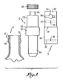
- Figure 1 est une vue schématique montrant côte à côte un bouchon irremplissable, une cape de fixation établie suivant l'invention et la partie supérieure ou goulot de la bouteille correspondante, ledit goulot étant représenté en coupe axiale afin de mieux faire apparaître son profil.
- Figure 2 est une coupe axiale de l'ensemble une fois mis en place sur une bouteille.
- Figure 3 reproduit fig. 2 après la première utilisation du liquide contenu dans la bouteille.
- Figure 1 is a schematic view showing side by side an irreplaceable cap, a fixing cap established according to the invention and the upper part or neck of the corresponding bottle, said neck being shown in axial section to better show its profile.
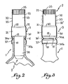
- Figure 2 is an axial section of the assembly once placed on a bottle.
- Figure 3 reproduced in fig. 2 after the first use of the liquid contained in the bottle.
En fig. 1 la référence 1 désigne le goulot d'une bouteille de type classique. Ce goulot 1 comporte à son sommet un renflement annulaire 10 creusé d'une gorge 11 à profil arrondi en section, qui détermine de la sorte une collerette supérieure 12 bordant l'ouverture de la bouteille. Cette ouverture est destinée à être obturée à l'aide d'un bouchon 2 du type irremplissable, dont le corps présente une partie inférieure 20 propre à être introduite de manière étanche dans le goulot 1 et solidaire d'une partie renflée 21 qui limite l'enfoncement ; la partie 21 se raccorde, par l'intermédiaire d'un épaulement tronconique 22, à une partie supérieure 23 à plus petit diamètre, laquelle est solidaire d'un bec verseur terminal 24. Ce dernier est normalement fermé de manière étanche par une capsule amovible 25 dont le diamètre extérieur coïncide avec celui de la partie 23.In fig. 1 the
L'agencement intérieur du bouchon irremplissable 2 peut être de tout type connu en pratique. L'invention concerne uniquement le mode de fixation de ce bouchon 2 sur le goulot 1 de telle sorte que l'agencement en cause ne fera l'objet d'aucune description.The internal arrangement of the
La fixation est assurée à l'aide d'une cape de surbouchage 3 qu'on peut supposer être réalisée en métal mince ou en matière synthétique. Cette cape présente une partie inférieure 30 dont le diamètre intérieur est sensiblement égal au diamètre extérieur de la partie renflée 21 et qui se raccorde par un épaulement tronconique 31 à une partie supérieure 32 à plus petit diamètre, fermée à son sommet par un fond transversal à profil circulaire en plan. A la manière en soi connue la partie supérieure 32 est pourvue d'une bague déchirable de garantie 33 solidaire d'une patte ou tirette 34 ; cette bague 33 est déterminée par deux amincissements ou « saignées » de la cape, figurés sous la forme de tracés interrompus, lesdits amincissements permettant un déchirage aisé.The fixing is ensured by means of an
Par ailleurs et conformément à l'invention l'on a fait comporter à la partie supérieure 32 de la cape 3 une bande annulaire 35 à faible résistance, de conception et de réalisation analogues à celles de la bague 33 sus-décrite ; cette bande 35, disposée entre l'épaulement 31 et la bague déchirable 33, présente en un point de sa longueur deux fentes transversales qui se font face en déterminant entre leurs extrémités en vis-à-vis un pontet de liaison 36 dont la résistance à la traction est évidemment très réduite. Une bande similaire 37, elle-même pourvue d'un pontet identique 36, est prévue sur la partie renflée 30 de la cape, à une faible distance du bord inférieur ouvert de celle-ci.Furthermore and in accordance with the invention, the
On comprend que la cape 3 est susceptible d'être mise en place sur le bouchon 2 afin de coiffer la partie supérieure de celui-ci, équipée de la capsule 25. Cet ensemble 2-3 peut être assujetti sur le goulot 1 de la bouteille préalablement remplie, la retenue dudit ensemble étant assurée en effectuant une opération de rétreinte 30a (fig. 2) pour que la partie inférieure 30 de la cape vienne épouser la gorge 11 du goulot, et un sertissage inférieur 30b afin que le bord libre de ladite cape se resserre immédiatement au-dessous du renflement 10. Pour avoir accès au contenu de la bouteille ainsi bouchée, l'utilisateur doit éliminer la bague de garantie 33 et le haut de la partie 32 de façon à libérer la capsule 25, comme illustré en fig. 3 ; la première utilisation de la bouteille est ainsi rendue apparente.It is understood that the
Etant donné que le bouchon 2 interdit formellement tout remplissage par suite de son agencement interne, la seule solution qui reste à un fraudeur consiste évidemment à tenter de procéder au retrait de ce bouchon lui-même pour découvrir l'ouverture du goulot 1. A cet effet il doit, avec une lame ou autre outil très mince introduit entre le bord supérieur découpé de la partie 32 et la partie 23 correspondante du bouchon, redresser par expansion ladite partie 32 en vue de lui conférer le profil indiqué en 32' en fig. 3, profil qui présente un diamètre étal à celui de la partie renflée 21 et qui permettrait ainsi le passage de cette dernière à travers l'ouverture supérieure de la cape. Mais la déformation ainsi opérée provoque immanquablement la rupture du pontet 36 de la bande 35 et la déchirure annulaire de celle-ci, si bien que le remplissage frauduleux deviendrait parfaitement visible quelles que soient les précautions prises pour remettre en place le bouchon après remplissage et remodeler la partie supérieure 32 de la cape.Given that the
Le résultat serait identique dans le cas où le fraudeur tenterait de procéder au retrait du bouchon 2 par intervention au niveau du bord inférieur de la cape 3. Certes il pourra sans trop de difficulté éliminer le sertissage 30b, mais lorsqu'il tentera d'accéder à la zone rétreinte 30a en vue d'obtenir le profil droit montré en 30' et être en mesure de retirer le bouchon 2 avec la cape 3, la bande 37 se rompra dans les mêmes conditions que la bande supérieure 35 et rendra apparent le remplissage frauduleux.The result would be identical in the case where the fraudster would attempt to remove the
Toute tentative d'extraction du bouchon 2 est rendue ainsi parfaitement visible, de telle sorte que la cape 2 assure une retenue absolument inviolable dudit bouchon. Il va de soi que l'agencement précis des bandes 35 et 37 de leur positionnement sur la cape peuvent varier dans une large mesure en fonction du profil extérieur particulier du bouchon irremplissable et de la conformation du goulot 1.Any attempt to extract the
On conçoit que les bandes 35 et 37 à faible résistance au déchirage sont susceptibles d'être établies de toute manière appropriée (amincissement ou saignée continu, perforations du type timbre-poste, etc...), comme la bague de garantie 33.It is understood that the
Claims (2)
Priority Applications (1)
| Application Number | Priority Date | Filing Date | Title |
|---|---|---|---|
| AT81420112T ATE9885T1 (en) | 1980-07-29 | 1981-07-24 | SAFETY CAP FOR THE ORIGINALITY-SECURE FIXING OF STOPPERS, WITH AN REFILL PREVENTING DEVICE, ON BOTTLES AND OTHER CONTAINERS. |
Applications Claiming Priority (2)
| Application Number | Priority Date | Filing Date | Title |
|---|---|---|---|
| FR8017009A FR2487786B1 (en) | 1980-07-29 | 1980-07-29 | SECURITY CAP FOR THE INVIOLABLE FIXING OF IRREMPLILLABLE TYPE CAPS ON BOTTLES AND OTHER CONTAINERS |
| FR8017009 | 1980-07-29 |
Publications (2)
| Publication Number | Publication Date |
|---|---|
| EP0045708A1 EP0045708A1 (en) | 1982-02-10 |
| EP0045708B1 true EP0045708B1 (en) | 1984-10-17 |
Family
ID=9244784
Family Applications (1)
| Application Number | Title | Priority Date | Filing Date |
|---|---|---|---|
| EP81420112A Expired EP0045708B1 (en) | 1980-07-29 | 1981-07-24 | Security cap for the tamper-proof fastening of non refillable stoppers for bottles and other containers |
Country Status (5)
| Country | Link |
|---|---|
| EP (1) | EP0045708B1 (en) |
| AT (1) | ATE9885T1 (en) |
| DE (1) | DE3166711D1 (en) |
| ES (1) | ES268530Y (en) |
| FR (1) | FR2487786B1 (en) |
Families Citing this family (1)
| Publication number | Priority date | Publication date | Assignee | Title |
|---|---|---|---|---|
| CN107310842B (en) * | 2017-08-08 | 2023-06-16 | 四川省宜宾普拉斯包装材料有限公司 | A kind of anti-counterfeiting packaging box |
Family Cites Families (5)
| Publication number | Priority date | Publication date | Assignee | Title |
|---|---|---|---|---|
| FR1016974A (en) * | 1950-03-31 | 1952-11-27 | Tamper-evident pouring cap for all containers | |
| FR2077685B1 (en) * | 1970-02-05 | 1974-03-15 | Bouchon Couronne | |
| FR2203751B1 (en) * | 1972-10-25 | 1978-05-26 | Bereziat Andre | |
| FR2340256A2 (en) * | 1976-02-04 | 1977-09-02 | Bouchage Mecanique | Dispenser with no refilling valve for bottle - has loose ball in cage permitting contents flow but sealing bottle if refilling attempted |
| FR2421118A1 (en) * | 1978-01-10 | 1979-10-26 | Ug Closures & Plastics Ltd | Tamper proof drink dispenser - has valve on bottle neck retained by remainder of metal cap for limited freedom |
-
1980
- 1980-07-29 FR FR8017009A patent/FR2487786B1/en not_active Expired
-
1981
- 1981-07-24 AT AT81420112T patent/ATE9885T1/en not_active IP Right Cessation
- 1981-07-24 DE DE8181420112T patent/DE3166711D1/en not_active Expired
- 1981-07-24 EP EP81420112A patent/EP0045708B1/en not_active Expired
- 1981-07-28 ES ES1981268530U patent/ES268530Y/en not_active Expired
Also Published As
| Publication number | Publication date |
|---|---|
| ES268530U (en) | 1983-06-01 |
| EP0045708A1 (en) | 1982-02-10 |
| DE3166711D1 (en) | 1984-11-22 |
| FR2487786B1 (en) | 1985-10-18 |
| FR2487786A1 (en) | 1982-02-05 |
| ES268530Y (en) | 1983-12-01 |
| ATE9885T1 (en) | 1984-11-15 |
Similar Documents
| Publication | Publication Date | Title |
|---|---|---|
| EP3741703B1 (en) | Screw cap intended to remain attached to a container after opening of the container | |
| CA2057889C (en) | Pourer for bottles and such containers with a borer element to perforate container pouring spout lid | |
| EP0244327B1 (en) | Container spout provided with means for preventing refilling after dispensing with the initial contents | |
| EP0270134A1 (en) | Pouring closure | |
| EP0268538A1 (en) | Cap for a container, initially closed by a pierceable membrane | |
| WO1994018084A1 (en) | Screw-top closure with a tamper-evident strip | |
| FR2729924A1 (en) | PRODUCT DISPENSING BOTTLE | |
| FR2496602A1 (en) | IMPROVED INVIOLABLE SHUTTER FOR A CONTAINER SUCH AS A BOTTLE | |
| EP0045708B1 (en) | Security cap for the tamper-proof fastening of non refillable stoppers for bottles and other containers | |
| WO2008152219A1 (en) | Cap for receptacle forming an additive reservoir | |
| FR2745794A1 (en) | CLOSURE DEVICE FOR A CONTAINER SUCH AS PARTICULARLY A BOTTLE FOR MEDICAL USE | |
| FR2701010A1 (en) | Clogging device with irreversible unscrewing. | |
| EP1364886A1 (en) | Closure with an element for piercing a cover foil on a container | |
| EP3984906B1 (en) | Screw cap intended to remain attached to a container after opening and which can be held in an open position | |
| EP1284905B1 (en) | Packaging for fluid product with hinge closure | |
| FR2647185A1 (en) | Security capsule for gas cylinders before they are first opened | |
| CH425504A (en) | Sealing cap for containers with threaded necks | |
| FR2722478A1 (en) | Bottle cap with pourer and safety closure | |
| EP3984905B1 (en) | Screw cap intended to remain attached to a container after opening, containing in particular an effervescent liquid | |
| EP0166664A2 (en) | Plastic protecting capsule | |
| FR1389177A (en) | Improvements to tamper-proof closing devices for crown ring necks | |
| FR2748260A1 (en) | INVIOLABLE BINING DEVICE FOR A CONTAINER SUCH AS A BOTTLE OR BOTTLE | |
| BE644177A (en) | ||
| BE514673A (en) | Closure for containers of all types | |
| FR2778643A1 (en) | Tamperproof device especially for bottle cap of synthetic material |
Legal Events
| Date | Code | Title | Description |
|---|---|---|---|
| PUAI | Public reference made under article 153(3) epc to a published international application that has entered the european phase |
Free format text: ORIGINAL CODE: 0009012 |
|
| AK | Designated contracting states |
Designated state(s): AT BE CH DE GB IT LU NL SE |
|
| 17P | Request for examination filed |
Effective date: 19820324 |
|
| ITF | It: translation for a ep patent filed | ||
| GRAA | (expected) grant |
Free format text: ORIGINAL CODE: 0009210 |
|
| AK | Designated contracting states |
Designated state(s): AT BE CH DE GB IT LI LU NL SE |
|
| PG25 | Lapsed in a contracting state [announced via postgrant information from national office to epo] |
Ref country code: SE Effective date: 19841017 Ref country code: NL Effective date: 19841017 Ref country code: AT Effective date: 19841017 |
|
| REF | Corresponds to: |
Ref document number: 9885 Country of ref document: AT Date of ref document: 19841115 Kind code of ref document: T |
|
| REF | Corresponds to: |
Ref document number: 3166711 Country of ref document: DE Date of ref document: 19841122 |
|
| NLV1 | Nl: lapsed or annulled due to failure to fulfill the requirements of art. 29p and 29m of the patents act | ||
| PG25 | Lapsed in a contracting state [announced via postgrant information from national office to epo] |
Ref country code: LU Free format text: LAPSE BECAUSE OF NON-PAYMENT OF DUE FEES Effective date: 19850731 |
|
| PLBE | No opposition filed within time limit |
Free format text: ORIGINAL CODE: 0009261 |
|
| STAA | Information on the status of an ep patent application or granted ep patent |
Free format text: STATUS: NO OPPOSITION FILED WITHIN TIME LIMIT |
|
| 26N | No opposition filed | ||
| PG25 | Lapsed in a contracting state [announced via postgrant information from national office to epo] |
Ref country code: LI Effective date: 19860731 Ref country code: CH Effective date: 19860731 Ref country code: BE Effective date: 19860731 |
|
| BERE | Be: lapsed |
Owner name: RIFFET MARCEL Effective date: 19860731 Owner name: VERON GHISLAINE EPOUSE FISCHER Effective date: 19860731 Owner name: FISCHER MARC Effective date: 19860731 |
|
| REG | Reference to a national code |
Ref country code: CH Ref legal event code: PL |
|
| GBPC | Gb: european patent ceased through non-payment of renewal fee | ||
| PG25 | Lapsed in a contracting state [announced via postgrant information from national office to epo] |
Ref country code: DE Effective date: 19870501 |
|
| PG25 | Lapsed in a contracting state [announced via postgrant information from national office to epo] |
Ref country code: GB Effective date: 19881118 |