EP0270134A1 - Pouring closure - Google Patents
Pouring closure Download PDFInfo
- Publication number
- EP0270134A1 EP0270134A1 EP87200543A EP87200543A EP0270134A1 EP 0270134 A1 EP0270134 A1 EP 0270134A1 EP 87200543 A EP87200543 A EP 87200543A EP 87200543 A EP87200543 A EP 87200543A EP 0270134 A1 EP0270134 A1 EP 0270134A1
- Authority
- EP
- European Patent Office
- Prior art keywords
- cap
- plug
- container
- relative
- proper
- Prior art date
- Legal status (The legal status is an assumption and is not a legal conclusion. Google has not performed a legal analysis and makes no representation as to the accuracy of the status listed.)
- Granted
Links
Images


Classifications
-
- B—PERFORMING OPERATIONS; TRANSPORTING
- B65—CONVEYING; PACKING; STORING; HANDLING THIN OR FILAMENTARY MATERIAL
- B65D—CONTAINERS FOR STORAGE OR TRANSPORT OF ARTICLES OR MATERIALS, e.g. BAGS, BARRELS, BOTTLES, BOXES, CANS, CARTONS, CRATES, DRUMS, JARS, TANKS, HOPPERS, FORWARDING CONTAINERS; ACCESSORIES, CLOSURES, OR FITTINGS THEREFOR; PACKAGING ELEMENTS; PACKAGES
- B65D51/00—Closures not otherwise provided for
- B65D51/18—Arrangements of closures with protective outer cap-like covers or of two or more co-operating closures
- B65D51/20—Caps, lids, or covers co-operating with an inner closure arranged to be opened by piercing, cutting, or tearing
- B65D51/22—Caps, lids, or covers co-operating with an inner closure arranged to be opened by piercing, cutting, or tearing having means for piercing, cutting, or tearing the inner closure
- B65D51/221—Caps, lids, or covers co-operating with an inner closure arranged to be opened by piercing, cutting, or tearing having means for piercing, cutting, or tearing the inner closure a major part of the inner closure being left inside the container after the opening
- B65D51/222—Caps, lids, or covers co-operating with an inner closure arranged to be opened by piercing, cutting, or tearing having means for piercing, cutting, or tearing the inner closure a major part of the inner closure being left inside the container after the opening the piercing or cutting means being integral with, or fixedly attached to, the outer closure
- B65D51/225—Caps, lids, or covers co-operating with an inner closure arranged to be opened by piercing, cutting, or tearing having means for piercing, cutting, or tearing the inner closure a major part of the inner closure being left inside the container after the opening the piercing or cutting means being integral with, or fixedly attached to, the outer closure and further comprising a device first inhibiting displacement of the outer closure
-
- B—PERFORMING OPERATIONS; TRANSPORTING
- B65—CONVEYING; PACKING; STORING; HANDLING THIN OR FILAMENTARY MATERIAL
- B65D—CONTAINERS FOR STORAGE OR TRANSPORT OF ARTICLES OR MATERIALS, e.g. BAGS, BARRELS, BOTTLES, BOXES, CANS, CARTONS, CRATES, DRUMS, JARS, TANKS, HOPPERS, FORWARDING CONTAINERS; ACCESSORIES, CLOSURES, OR FITTINGS THEREFOR; PACKAGING ELEMENTS; PACKAGES
- B65D47/00—Closures with filling and discharging, or with discharging, devices
- B65D47/04—Closures with discharging devices other than pumps
- B65D47/20—Closures with discharging devices other than pumps comprising hand-operated members for controlling discharge
- B65D47/24—Closures with discharging devices other than pumps comprising hand-operated members for controlling discharge with poppet valves or lift valves, i.e. valves opening or closing a passageway by a relative motion substantially perpendicular to the plane of the seat
- B65D47/241—Closures with discharging devices other than pumps comprising hand-operated members for controlling discharge with poppet valves or lift valves, i.e. valves opening or closing a passageway by a relative motion substantially perpendicular to the plane of the seat the valve being opened or closed by actuating a cap-like element
- B65D47/242—Closures with discharging devices other than pumps comprising hand-operated members for controlling discharge with poppet valves or lift valves, i.e. valves opening or closing a passageway by a relative motion substantially perpendicular to the plane of the seat the valve being opened or closed by actuating a cap-like element moving helically
-
- B—PERFORMING OPERATIONS; TRANSPORTING
- B65—CONVEYING; PACKING; STORING; HANDLING THIN OR FILAMENTARY MATERIAL
- B65D—CONTAINERS FOR STORAGE OR TRANSPORT OF ARTICLES OR MATERIALS, e.g. BAGS, BARRELS, BOTTLES, BOXES, CANS, CARTONS, CRATES, DRUMS, JARS, TANKS, HOPPERS, FORWARDING CONTAINERS; ACCESSORIES, CLOSURES, OR FITTINGS THEREFOR; PACKAGING ELEMENTS; PACKAGES
- B65D47/00—Closures with filling and discharging, or with discharging, devices
- B65D47/36—Closures with frangible parts adapted to be pierced, torn, or removed, to provide discharge openings
- B65D47/38—Closures with frangible parts adapted to be pierced, torn, or removed, to provide discharge openings with piercing means arranged to act subsequently as a valve to control the opening
-
- B—PERFORMING OPERATIONS; TRANSPORTING
- B65—CONVEYING; PACKING; STORING; HANDLING THIN OR FILAMENTARY MATERIAL
- B65D—CONTAINERS FOR STORAGE OR TRANSPORT OF ARTICLES OR MATERIALS, e.g. BAGS, BARRELS, BOTTLES, BOXES, CANS, CARTONS, CRATES, DRUMS, JARS, TANKS, HOPPERS, FORWARDING CONTAINERS; ACCESSORIES, CLOSURES, OR FITTINGS THEREFOR; PACKAGING ELEMENTS; PACKAGES
- B65D2251/00—Details relating to container closures
- B65D2251/0003—Two or more closures
- B65D2251/0006—Upper closure
- B65D2251/0025—Upper closure of the 47-type
-
- B—PERFORMING OPERATIONS; TRANSPORTING
- B65—CONVEYING; PACKING; STORING; HANDLING THIN OR FILAMENTARY MATERIAL
- B65D—CONTAINERS FOR STORAGE OR TRANSPORT OF ARTICLES OR MATERIALS, e.g. BAGS, BARRELS, BOTTLES, BOXES, CANS, CARTONS, CRATES, DRUMS, JARS, TANKS, HOPPERS, FORWARDING CONTAINERS; ACCESSORIES, CLOSURES, OR FITTINGS THEREFOR; PACKAGING ELEMENTS; PACKAGES
- B65D2251/00—Details relating to container closures
- B65D2251/0003—Two or more closures
- B65D2251/0037—Intermediate closure(s)
- B65D2251/0056—Intermediate closure(s) of the 47-type
-
- B—PERFORMING OPERATIONS; TRANSPORTING
- B65—CONVEYING; PACKING; STORING; HANDLING THIN OR FILAMENTARY MATERIAL
- B65D—CONTAINERS FOR STORAGE OR TRANSPORT OF ARTICLES OR MATERIALS, e.g. BAGS, BARRELS, BOTTLES, BOXES, CANS, CARTONS, CRATES, DRUMS, JARS, TANKS, HOPPERS, FORWARDING CONTAINERS; ACCESSORIES, CLOSURES, OR FITTINGS THEREFOR; PACKAGING ELEMENTS; PACKAGES
- B65D2251/00—Details relating to container closures
- B65D2251/0003—Two or more closures
- B65D2251/0068—Lower closure
- B65D2251/0093—Membrane
-
- B—PERFORMING OPERATIONS; TRANSPORTING
- B65—CONVEYING; PACKING; STORING; HANDLING THIN OR FILAMENTARY MATERIAL
- B65D—CONTAINERS FOR STORAGE OR TRANSPORT OF ARTICLES OR MATERIALS, e.g. BAGS, BARRELS, BOTTLES, BOXES, CANS, CARTONS, CRATES, DRUMS, JARS, TANKS, HOPPERS, FORWARDING CONTAINERS; ACCESSORIES, CLOSURES, OR FITTINGS THEREFOR; PACKAGING ELEMENTS; PACKAGES
- B65D2401/00—Tamper-indicating means
- B65D2401/15—Tearable part of the closure
- B65D2401/20—Frangible elements completely enclosed in closure skirt
Definitions
- the subject of the invention is a pouring plug device.
- It relates, in particular, to such a device suitable for being used for capping receptacles of the type of bottles or flasks intended to contain pasty or viscous products.
- the caps of containers containing such products must meet various conditions, sometimes contradictory, such as being easy to handle, low cost, good sealing to avoid alteration of the qualities of the packaged product, while making it possible to ensure the guarantees of safety required both by the users of the products having regard to the integrity of the contents of the container during its first use and as regards the manufacturing of the products having regard, also, to the conservation of the qualities of said products in the container over time.
- pouring caps have already been proposed comprising an internal seal, in the form of a membrane which closes the opening of the container on the one hand and, on the other hand, a security or tamper-evident strip which must be removed before the first use of the container to give access to its contents.
- An example of such a device more particularly intended to meet the standards imposed by the regulations concerning the packaging of dangerous liquids is described in FR-A-2 565 208.
- an object of the invention to provide such a device in which the opening of the container which it equips is closed by a cover as long as a first actuation has not taken place, and which prohibits such activation until a tamper-evident band has been removed.
- a pourer stopper device in particular for a flexible container of the type of those intended to contain a pasty or viscous product comprising a stopper proper shaped according to a cover provided with means for fixing to the neck of the container and a cap or capsule movable relative to said cap itself, as well as a guarantee or tamper-proof band connected in a detachable manner to said cap and which cooperates with said cap itself to prevent any relative movement of the cap relative to the cap itself as long that it has not been torn off, is characterized in that the cap and the plug proper are provided with complementary means preventing the separation of one from the other while guiding the movement of the first relative to the second, the first movement of said cap relative to the cap itself which follows the tearing of the guarantee strip causing the piercing of a membrane-shaped cover secured by its two faces, on the one hand, of the orifice of the opening of the container and, on the other hand, of the cap properly said, this first actuation simultaneously causing in said cap the opening of
- said complementary means consist most simply of a cam track and of helical screwing studs conjugate carried, one by the cap, and the others by the plug itself.
- the invention provides that the cap itself carries, on its crown face, a finger directed towards the outside of the container when the cap is in place, of a height such that the first actuation of the cap relative to the plug proper causes the end of said finger distant from the cap to cooperate with a sealing plug of an orifice of said cap to cause the tearing of the latter and thus form the outlet for the product contained in the container.
- the top face of the plug proper which carries the finger mentioned above also carries a chimney coaxial with said finger and whose diameter is substantially that of a circle limiting the lights made in said face and shaped according to parts of annular rings.
- the piercing members are formed by punches or the like provided at the ends of a skirt which depends on the cap, provision is advantageously made for the diameter of said skirt to be slightly less than that of the chimney of the plug proper, favoring in a to some extent the translational / rotational movement of the cap relative to the plug proper on the one hand and, on the other hand, the sealing of the plugging if provided on the free edge of the cap and the chimney, respectively, of the beads or the like.
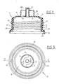
- FIGS. 1 to 5 illustrate the structure of a device according to the invention, intended to equip a container R, of the type of those with flexible walls and intended to enclose a pasty or viscous product. It essentially comprises a plug proper 10, FIGS. 2 and 3 and a cap or capsule 11, FIGS. 4 and 5.
- the plug 10 proper of PPO type plastic 2 for example, is molded according to a cylindrical body 12, having on its internal face a thread 13 intended to cooperate with the conjugate thread of the neck C of the container R, and a flat end wall 15 connected to the body 12 by a fold or shoulder 14.
- the wall 15 is pierced with at least two opposite openings 16 and 17 having in plan somewhat the shape of a part of a crown and between which there is erected, projecting from the external face 18 of the wall 15, a hollow finger 19 directed opposite the body 12 with respect to to said wall 15. From the latter, also protrudes, a chimney 20 coaxial with the finger 19, the diameter of which is substantially that of the circle limiting the openings 16 and 17 on their external periphery and which has at its free end and on its face int erne a slight bead 20a.
- the body 12 At its end distant from that of connection to the wall 15, the body 12 is shaped according to a frustoconical skirt 25, providing on its external face a planar support zone 26 connected to the external face 27 of said body by a cutaway 28 and on its internal face 29 has a toothing, of the rack type, not shown, adapted to cooperate with a corresponding toothing, also not shown, of the neck C of the container R to oppose the removal of the plug proper with respect to said container which , prior to the establishment of the plug proper and after filling is closed at its outlet by a cover 30, advantageously a thermosealed membrane on the flat end face 31 of the neck C.
- FIG. 4 With the plug 10 proper is suitable for cooperating the cap or capsule 11, Figures 4 and 5 and which, in the embodiment described and shown, comprises a cylindrical body 40 on the inner face 41 of which are cam tracks 42 one of which is shown in FIG. 4, said cam paths extending from a circular groove 42a formed in the vicinity of the free edge of the body and being designed to cooperate with at least two pins 45 and 46 of shapes and dimensions conjugates provided in equidistant zones on the external surface 27 of the body 12 of the plug 10 proper.
- a tamper-evident band 50 At the free end of the body 40 of the cap 11 is attached a tamper-evident band 50, one end of which has a gripping tongue 51 allowing the easy pulling of said tongue relative to the body 40 to which it is connected by a zone 52 very thin or with bridges, the height of said strip 50, as measured parallel to the axis A of the device, being substantially equal to the distance between the circular lower edge 53 of the body 40 of the bearing face 26 of the plug proper when the latter and the cap are secured to each other, in a first condition of the pouring plug which is that shown in FIG. 1 and which corresponds to that on leaving the packaging plant, that is to say say in particular with the cover 30 intact and the pins 45 and 46 in the groove 42a.
- the body 40 At its end distant from that at which is initially attached to the guarantee strip 50, the body 40 continues with a frusto-conical part 60 which ends in a wall 61 substantially orthogonal to the axis A of the device and the central zone of which is cut along arcs of a circle, as shown at 62 , 63 and 64 in Figure 5 to provide a central patch 70 connected to the rest of the wall by bridges 65, 66, 67, thin and easy to break when a force directed in the direction of arrow F is applied by finger 19 on said patch.
- a skirt 71 From the wall 61 depends, towards the inside of the cap, a skirt 71 with an external diameter corresponding substantially to the internal diameter of the chimney 20 and which, at its free end, has a slight bead 71a, similar to the bead 20a of the chimney 20.
- the skirt 71 is also shaped, on its free edge 72, along at least two opposite punches 73 each comprising a point 74 and which, when the device is assembled, are opposite the slots 16 and 17 of the plug 10 proper , then masked by the cover 30.
- the cover 30 After filling the container R with the product it is intended to contain, the cover 30 is heat sealed on the opening of the container in the case of conduction heat sealing and the entire device, that is to say the cap. 10 proper and the cap 11, is attached to the neck C of the container by screwing.
- the cap / seal assembly is, after filling, screwed onto the mold and heat sealed.
- the first step is to tear off the tamper-evident band 50, by a simple pull on the tab 51.
Abstract
Description
L'invention a pour objet un dispositif de bouchon verseur.The subject of the invention is a pouring plug device.
Elle vise, en particulier, un tel dispositif propre à être utilisé pour le bouchage de récipients du type des bouteilles ou flacons prévus pour renfermer des produits pâteux ou visqueux.It relates, in particular, to such a device suitable for being used for capping receptacles of the type of bottles or flasks intended to contain pasty or viscous products.
Les bouchons de récipients contenant de tels produits doivent satisfaire à des conditions variées, parfois contradictoires, comme être d'une manipulation aisée, d'un faible coût, d'une bonne étanchéité pour éviter l'altération des qualités du produit emballé, tout en permettant d'assurer les garanties de sécurité exigées à la fois par les utilisateurs des produits eu égard à l'intégrité du contenu du récipient lors de sa première utilisation et en ce qui concerne les fabrications des produits eu égard, également, à la conservation des qualités desdits produits dans le récipient au cours du temps.The caps of containers containing such products must meet various conditions, sometimes contradictory, such as being easy to handle, low cost, good sealing to avoid alteration of the qualities of the packaged product, while making it possible to ensure the guarantees of safety required both by the users of the products having regard to the integrity of the contents of the container during its first use and as regards the manufacturing of the products having regard, also, to the conservation of the qualities of said products in the container over time.
Pour répondre à ces conditions, en particulier à celles mentionnées ci-dessus, on a déjà proposé des bouchons verseurs comprenant un opercule interne, sous forme d'une membrane qui obture le débouché du récipient d'une part et, d'autre part, une bande de garantie ou d'inviolabilité qui doit être retirée préalablement à la première utilisation du récipient pour donner accès au contenu de celui-ci. Un exemple d'un tel dispositif, plus particulièrement prévu pour satisfaire aux normes imposées par la règlementation concernant le conditionnement de liquides dangereux est décrit dans FR-A-2 565 208. Il prévoit un opercule de fermeture du débouché du récipient moulé d'une pièce avec un organe verseur dont il est arrachable, de sorte que la capsule que comporte le dispositif doit d'abord être retirée du verseur pour permettre l'accès à l'opercule, la capsule ne pouvant pas ainsi être rendue inséparable du verseur. Une telle disposition, à savoir une capsule inséparable du verseur est cependant très intéressante dans de très nombreuses applications, notamment celles qui concernent le condition nement de récipients pour produits alimentaires comme, par exemple, et que sans que cette indication ait quelque caractère limitatif que ce soit, des récipients souples pour condiments comme de la moutarde ou du ketchup, etc... ou des produits tels que des shampooings etc...To meet these conditions, in particular those mentioned above, pouring caps have already been proposed comprising an internal seal, in the form of a membrane which closes the opening of the container on the one hand and, on the other hand, a security or tamper-evident strip which must be removed before the first use of the container to give access to its contents. An example of such a device, more particularly intended to meet the standards imposed by the regulations concerning the packaging of dangerous liquids is described in FR-A-2 565 208. It provides a closure for closing the outlet of the molded container of a piece with a pouring member from which it is tear-off, so that the capsule that the device comprises must first be withdrawn from the pourer to allow access to the cover, the capsule cannot thus be made inseparable from the pourer. Such an arrangement, namely a capsule separable from the pourer, is however very advantageous in very many applications, in particular those relating to the condition containers for food products such as, for example, and without this indication having any limiting nature whatsoever, flexible containers for condiments such as mustard or ketchup, etc. or products such as shampoos etc. ...
C'est, précisément, un but de l'invention de fournir un dispositif de bouchon verseur perfectionné que satisfasse à toutes les conditions exigées, rappelées ci-dessus, en particulier celle mentionné en dernier lieu.It is, precisely, an object of the invention to provide an improved pouring plug device which satisfies all the required conditions, recalled above, in particular that mentioned last.
C'est, à cet égard, un but de l'invention de fournir un tel dispositif dans lequel le débouché du récipient qu'il équipe soit obturé par un opercule aussi longtemps qu'un premier actionnement n'a pas eu lieu, et qui interdise un tel actionnement tant qu'une bande d'inviolabilité n'a pas été retirée.It is, in this regard, an object of the invention to provide such a device in which the opening of the container which it equips is closed by a cover as long as a first actuation has not taken place, and which prohibits such activation until a tamper-evident band has been removed.
C'est, aussi, un but de l'invention de fournir un tel dispositif de bouchon-verseur bien approprié pour équiper des récipients pour produits pâteux ou visqueux, par le fait qu'il assure en permanence une certaine protection du contenu du récipient, tout en étant à bouchage et débouchage simples et sûrs.It is also an object of the invention to provide such a pouring plug device which is very suitable for equipping containers for pasty or viscous products, by the fact that it permanently ensures a certain protection of the contents of the container, while being simple and safe to plug and unclog.
Un dispositif de bouchon verseur selon l'invention, notamment pour un récipient souple du type de ceux destinés à contenir un produit pâteux ou visqueux comportant un bouchon proprement dit conformé suivant un capot muni de moyens de fixation au goulot du récipient et une coiffe ou capsule mobile par rapport audit bouchon proprement dit, ainsi qu'une bande de garantie ou d'inviolabilité reliée de façon arrachable à ladite coiffe et qui coopère avec ledit bouchon proprement dit pour interdire tout mouvement relatif de la coiffe par rapport au bouchon proprement dit aussi longtemps qu'elle n'a pas été arrachée, est caractérisé en ce que la coiffe et le bouchon proprement dit sont munis de moyens complémentaires interdisant la séparation de l'un par rapport à l'autre tout en assurant le guidage du déplacement de la première par rapport au second, le premier déplacement de ladite coiffe par rapport au bouchon proprement dit qui suit l'arrachage de la bande de garantie provoquant le perçage d'un opercule en forme de membrane solidarisé par ses deux faces, d'une part, de l'orifice du débouché du récipient et, d'autre part, du bouchon proprement dit, ce premier actionnement provoquant simultanément dans ladite coiffe le débouchage d'un orifice de sortie du produit contenu dans le récipient.A pourer stopper device according to the invention, in particular for a flexible container of the type of those intended to contain a pasty or viscous product comprising a stopper proper shaped according to a cover provided with means for fixing to the neck of the container and a cap or capsule movable relative to said cap itself, as well as a guarantee or tamper-proof band connected in a detachable manner to said cap and which cooperates with said cap itself to prevent any relative movement of the cap relative to the cap itself as long that it has not been torn off, is characterized in that the cap and the plug proper are provided with complementary means preventing the separation of one from the other while guiding the movement of the first relative to the second, the first movement of said cap relative to the cap itself which follows the tearing of the guarantee strip causing the piercing of a membrane-shaped cover secured by its two faces, on the one hand, of the orifice of the opening of the container and, on the other hand, of the cap properly said, this first actuation simultaneously causing in said cap the opening of an outlet for the product contained in the container.
Dans une forme de réalisation préférée, lesdits moyens complémentaires sont constitués le plus simplement par un chemin de came et des têtons de vissage hélicoïdal conjuguées portées, l'une par la coiffe, et les autres par le bouchon proprement dit.In a preferred embodiment, said complementary means consist most simply of a cam track and of helical screwing studs conjugate carried, one by the cap, and the others by the plug itself.
Dans cette même forme de réalisation, on prévoit, selon une autre caractéristique de l'invention, que des lumières soient ménagées dans le sommet du bouchon proprement dit, lesdites lumières, obturées aussi longtemps que l'opercule en forme de membrane n'a pas été percé, servant à livrer passage à des organes de perçage de ladite membrane solides de la coiffe, lors du premier mouvement relatif du bouchon et de la coiffe.In this same embodiment, provision is made, according to another characteristic of the invention, for openings to be made in the top of the plug proper, said openings, closed as long as the membrane-shaped cover has not been pierced, serving to give passage to the piercing members of said solid membrane of the cap, during the first relative movement of the cap and the cap.
Dans une forme d'exécution préférée, l'invention prévoit que le bouchon proprement dit porte, sur sa face de sommet, un doigt dirigé vers l'extérieur du récipient lorsque le bouchon est en place, de hauteur telle que le premier actionnement de la coiffe par rapport au bouchon proprement dit amène l'extrémité dudit doigt distante du bouchon à coopérer avec une pastille d'obturation d'un orifice de ladite coiffe pour provoquer l'arrachage de celle-ci et ainsi former l'orifice de sortie du produit contenu dans le récipient.In a preferred embodiment, the invention provides that the cap itself carries, on its crown face, a finger directed towards the outside of the container when the cap is in place, of a height such that the first actuation of the cap relative to the plug proper causes the end of said finger distant from the cap to cooperate with a sealing plug of an orifice of said cap to cause the tearing of the latter and thus form the outlet for the product contained in the container.
Selon encore une autre caractéristique de l'invention, la face de sommet du bouchon proprement dit qui porte le doigt mentionné ci-dessus, porte également une cheminée coaxiale audit doigt et dont le diamètre est sensiblement celui d'un cercle limitant les lumières ménagées dans ladite face et conformées suivant des parties de couronnes annulaires.According to yet another characteristic of the invention, the top face of the plug proper which carries the finger mentioned above, also carries a chimney coaxial with said finger and whose diameter is substantially that of a circle limiting the lights made in said face and shaped according to parts of annular rings.
Lorsque les organes de perçage sont ménagés par des poinçons ou analogues prévus aux extrémités d'une jupe qui dépend de la coiffe, on prévoit avantageusement que le diamètre de ladite jupe soit légèrement inférieur à celui de la cheminée du bouchon proprement dit, favorisant dans une certaine mesure le mouvement de translation/rotation de la coiffe par rapport au bouchon proprement dit d'une part et, d'autre part, l'étanchéité du bouchage si l'on prévoit sur le bord libre de la coiffe et de la cheminée, respectivement, des bourrelets ou analogues.When the piercing members are formed by punches or the like provided at the ends of a skirt which depends on the cap, provision is advantageously made for the diameter of said skirt to be slightly less than that of the chimney of the plug proper, favoring in a to some extent the translational / rotational movement of the cap relative to the plug proper on the one hand and, on the other hand, the sealing of the plugging if provided on the free edge of the cap and the chimney, respectively, of the beads or the like.
L'invention sera mieux comprise par la description qui suit, faite à titre d'exemple, et en référence aux dessins annexés dans lesquels :
- La figure 1 est une vue d'ensemble du dispositif de bouchon verseur selon l'invention préalablement à sa première utilisation.
- La figure 2 est une vue du bouchon proprement dit, en coupe selon la figure 2-2 de la figure 3.
- La figure 3 est une vue de dessus de ce bouchon proprement dit.
- La figure 4 est une vue en coupe selon la ligne 4-4 de la figure 5 montrant la capsule ou coiffe munie de sa bande d'inviolabilité.
- La figure 5 est une vue de dessus de la capsule ou coiffe du dispositif du bouchon verseur selon l'invention.
- La figure 6 montre deux demi-vues du dispositif de bouchon verseur pour des conditions différentes d'utilisation de celui-ci.
- Figure 1 is an overview of the pouring plug device according to the invention prior to its first use.
- FIG. 2 is a view of the plug proper, in section according to FIG. 2-2 of FIG. 3.
- Figure 3 is a top view of the plug itself.
- Figure 4 is a sectional view along line 4-4 of Figure 5 showing the capsule or cap provided with its tamper-evident band.
- Figure 5 is a top view of the capsule or cap of the pouring plug device according to the invention.
- FIG. 6 shows two half-views of the pouring plug device for different conditions of use thereof.
On se réfère d'abord aux figures 1 à 5 qui illustrent la structure d'un dispositif selon l'invention, destiné à équiper un récipient R, du type de ceux à parois souples et prévu pour enfermer un produit pâteux ou visqueux. Il comprend essentiellement un bouchon proprement dit 10, figures 2 et 3 et une coiffe ou capsule 11, figures 4 et 5. Le bouchon 10 proprement dit en matière plastique du type PPO 2, par exemple, est moulé suivant un corps cylindrique 12, présentant sur sa face interne un filetage 13 destiné à coopérer avec le filetage conjugé du col C du récipient R, et une paroi plane d'extrémité 15 reliée au corps 12 par un pli ou épaulement 14. La paroi 15 est percée d'au moins deux lumières opposées 16 et 17 ayant en plan quelque peu la forme d'une partie de couronne et entre lesquelles est érigé, en saillie sur la face externe 18 de la paroi 15, un doigt creux 19 dirigé à l'opposé du corps 12 par rapport à ladite paroi 15. De cette dernière, fait également saillie, une cheminée 20 coaxiale au doigt 19, dont le diamètre est sensiblement celui du cercle limitant les lumières 16 et 17 sur leur périphérie externe et qui présente à son extrémité libre et sur sa face interne un léger bourrelet 20a.Reference is first made to FIGS. 1 to 5 which illustrate the structure of a device according to the invention, intended to equip a container R, of the type of those with flexible walls and intended to enclose a pasty or viscous product. It essentially comprises a plug proper 10, FIGS. 2 and 3 and a cap or
A son extrémité distante de celle de raccord à la paroi 15 le corps 12 est conformé suivant une jupe tronconique 25, ménageant sur sa face externe une zone d'appui plane 26 reliée à la face externe 27 dudit corps par un pan coupé 28 et sur sa face interne 29 présente une denture, du type crémaillère, non représentée, propre à coopérer avec une denture correspondante, également non représentée, du col C du récipient R pour s'opposer à l'enlèvement du bouchon proprement dit par rapport audit récipient lequel, préalablement à la mise en place du bouchon proprement dit et après remplissage est obturé à son débouché par un opercule 30, avantageusement une membrane thermo-scellée sur la face plane d'extrémité 31 du col C.At its end distant from that of connection to the
Avec le bouchon 10 proprement dit est propre à coopérer la coiffe ou capsule 11, figures 4 et 5 et qui, dans la forme de réalisation décrite et représentée, comprend un corps cylindrique 40 sur la face interne 41 duquel sont ménagées des chemins de came 42 dont une est montrée sur la figure 4, lesits chemins de came s'étendant à partir d'une gorge circulaire 42a ménagée au voisinage du bord libre du corps et étant prévues pour coopérer avec au moins deux têtons 45 et 46 de formes et de dimensions conjugées prévues en des zones equidistantes sur la surface externe 27 du corps 12 du bouchon 10 proprement dit.With the
A l'extrémité libre du corps 40 de la coiffe 11 est attachée une bande d'inviolabilité 50 dont une extrémité présente une languette 51 de préhension permettant l'arrachage facile de ladite languette par rapport au corps 40 auquel elle est reliée par une zone 52 de très faible épaisseur ou par des pontets, la hauteur de ladite bande 50, comme mesurée parallèlement à l'axe A du dispositif, étant sensiblement égale à la distance qui sépare le bord inférieur circulaire 53 du corps 40 de la face d'appui 26 du bouchon proprement dit lorsque celui-ci et la coiffe sont solidarisés entre eux, dans une première condition du bouchon verseur qui est celle montrée sur la figure 1 et qui correspond à celle de sortie de l'usine de conditionement, c'est-à-dire en particulier avec l'opercule 30 intact et les têtons 45 et 46 dans la gorge 42a.At the free end of the
A son extrémité distante de celle à laquelle est initialement attachée la bande de garantie 50, le corps 40 se poursuit par une partie tronconique 60 laquelle se termine par une paroi 61 sensiblement orthogonale à l'axe A du dispositif et dont la zone centrale est découpée suivant des arcs de cercle, comme montrés en 62, 63 et 64 sur la figure 5 pour ménager une pastille centrale 70 reliée au reste de la paroi par des pontets 65, 66, 67, de faible épaisseur et faciles à briser lorsqu'une force dirigée dans le sens de la flèche F est appliquée par le doigt 19 sur ladite pastille.At its end distant from that at which is initially attached to the
De la paroi 61 dépend, vers l'intérieur de la coiffe, une jupe 71 d'un diamètre externe correspondant sensiblement au diamètre interne de cheminée 20 et qui, à son extrémité libre, présente un léger bourrelet 71a, analogue au bourrelet 20a de la cheminée 20. La jupe 71 est aussi conformée, sur son bord libre 72, suivant au moins deux poinçons 73 opposés comportant chacun une pointe 74 et qui, lorsque le dispositif est assemblé, sont en regard des lumières 16 et 17 du bouchon 10 proprement dit, alors masquées par l'opercule 30.From the
Le fonctionnement du dispositif selon l'invention résulte immédiatement de ce qui précède.The operation of the device according to the invention results immediately from the above.
Après remplissage du récipient R par le produit qu'il est destiné à contenir, l'opercule 30 est thermoscellé sur le débouché du récipient dans le cas du thermoscellage par conduction et l'ensemble du dispositif, c'est-à-dire le bouchon 10 proprement dit et la coiffe 11, est rapporté sur le col C du récipient par vissage. Lors du thermoscellage par induction, l'ensemble bouchon/opercule est, après remplissage, vissé sur le facon et thermoscellé. Lorsque, à partir de cette condition, on souhaite utiliser le récipient pour la première fois, on procède d'abord à l'arrachage de la bande d'inviolabilité 50, par une simple traction sur la languette 51. Il n'existe alors plus d'obstacle au mouvement relatif de la coiffe par rapport au bouchon proprement dit et l'on peut alors percer l'opercule 30 en déplaçant la coiffe 11 par rapport au bouchon proprement dit, en faisant progresser la coiffe par un mouvement hélicoïdal qui fait coopérer les chemins de came 42 et les têtons 45 et 46 jusqu'à amener ladite coiffe dans la position montrée sur la partie gauche de la figure 6. Au cours de ce mouvement, les poinçons 73 perforent l'opercule 30 et le découpent sensiblement suivant la périphérie des lumières 16, 17.After filling the container R with the product it is intended to contain, the
Simultanément, au cours de ce premier actionnement, la coopération du doigt 19 et de la pastille 70 de la paroi 61 provoque la rupture des pontets 65, 66 et 67 pour former l'orifice de sortie O du produit, comme montré sur la partie droite de la figure 6 où le trajet de sortie du produit est montré par la flèche en pointillés T à partir du récipient, au travers des lumières 16, 17, dans l'espace ménagé entre le doigt 19 et la jupe 71, jusqu'à l'orifice O.Simultaneously, during this first actuation, the cooperation of the
Lorsque, après utilisation du récipient, celui-ci doit être rebouché, un actionnement inverse de la coiffe par rapport au bouchon assure la fermeture, c'est-à-dire le retour dans la condition montrée sur la partie gauche de la figure 6.When, after use of the container, it must be capped, an inverse actuation of the cap relative to the cap ensures the closure, that is to say the return to the condition shown on the left side of FIG. 6.
La présence des bourrelets 71a et 20a qui coopèrent avec la cheminée 20 et la jupe 71, respectivement, contribue à la bonne étanchéité.The presence of the
Claims (6)
Priority Applications (1)
| Application Number | Priority Date | Filing Date | Title |
|---|---|---|---|
| AT87200543T ATE70243T1 (en) | 1986-11-19 | 1987-03-25 | POUR CAP. |
Applications Claiming Priority (2)
| Application Number | Priority Date | Filing Date | Title |
|---|---|---|---|
| BE0/217442A BE905791A (en) | 1986-11-19 | 1986-11-19 | POURING CAP. |
| BE217442 | 1986-11-19 |
Publications (2)
| Publication Number | Publication Date |
|---|---|
| EP0270134A1 true EP0270134A1 (en) | 1988-06-08 |
| EP0270134B1 EP0270134B1 (en) | 1991-12-11 |
Family
ID=3844096
Family Applications (1)
| Application Number | Title | Priority Date | Filing Date |
|---|---|---|---|
| EP87200543A Expired - Lifetime EP0270134B1 (en) | 1986-11-19 | 1987-03-25 | Pouring closure |
Country Status (9)
| Country | Link |
|---|---|
| US (1) | US4779764A (en) |
| EP (1) | EP0270134B1 (en) |
| JP (1) | JPS63203562A (en) |
| AT (1) | ATE70243T1 (en) |
| BE (1) | BE905791A (en) |
| CA (1) | CA1280078C (en) |
| DE (1) | DE3775183D1 (en) |
| ES (1) | ES2028045T3 (en) |
| GR (1) | GR3003789T3 (en) |
Cited By (6)
| Publication number | Priority date | Publication date | Assignee | Title |
|---|---|---|---|---|
| EP0468265A2 (en) * | 1990-07-21 | 1992-01-29 | Beiersdorf Aktiengesellschaft | Dispenser |
| FR2673601A1 (en) * | 1991-03-08 | 1992-09-11 | Astra Plastique | Cap with integrated cutting device, equipped with a guarantee ring |
| EP0598223A2 (en) * | 1992-10-27 | 1994-05-25 | LUMSON S.r.l. | Dispenser cap for a fluid substance container, with a movable dispensing nozzle |
| EP0922645A1 (en) * | 1997-12-11 | 1999-06-16 | Gurit-Essex AG | Applicator for low viscosity products |
| EP1035030A1 (en) | 1999-03-08 | 2000-09-13 | Percopack S.r.l. | Dispenser cap for fluid substance containers |
| EP1364885A1 (en) | 2002-05-22 | 2003-11-26 | LUMSON S.p.A. | Dispenser cap with security seal for fluid substance containers |
Families Citing this family (67)
| Publication number | Priority date | Publication date | Assignee | Title |
|---|---|---|---|---|
| MX168418B (en) * | 1988-02-15 | 1993-04-27 | Maquinas Fabricacion Sa De | INTEGRAL SUPPLY PLUG |
| MX168419B (en) * | 1988-02-15 | 1993-04-27 | Maquinas Fabricacion Sa De | INTEGRAL SUPPLY PLUG |
| DK158289A (en) * | 1988-04-13 | 1989-10-14 | Colgate Palmolive Co | BASKET WITH DOSING DEVICE |
| FR2644432B2 (en) * | 1988-05-11 | 1991-06-14 | Morel Simone | ROTATING ENVELOPE CAPSULE FOR VIALS AND SIMILAR CONTAINERS |
| US4976379A (en) * | 1988-05-23 | 1990-12-11 | Sloan Daniel C | Dispensing container with integral funnel |
| FR2635086B1 (en) * | 1988-08-03 | 1991-01-25 | Emballages Conseils Etudes | APPLICATOR MOUTHPIECE FOR SCREW TUBES AND OTHER CONTAINERS |
| CH678843A5 (en) * | 1989-06-09 | 1991-11-15 | Alfatechnic Ag | |
| FR2660911B1 (en) * | 1990-04-13 | 1992-07-03 | Astra Plastique | CAPPING DEVICE WITH ROTATING CAP. |
| US5111954A (en) * | 1990-10-02 | 1992-05-12 | Ipl Inc. | Tamper evident container |
| US5104008A (en) * | 1990-12-03 | 1992-04-14 | Northern Engineering And Plastics Corp. | Resealable bottle cap with push-pull closure |
| US5320235A (en) * | 1993-04-08 | 1994-06-14 | Joyce Molding Corporation | Thermoplastic molded cap with integral tear band |
| US5507416A (en) * | 1994-09-29 | 1996-04-16 | West Penn Plastics | Tamper evident push pull resealable cap |
| US5657906A (en) * | 1994-09-29 | 1997-08-19 | West Penn Plastics | Tamper evident push pull resealable cap |
| IT1269022B (en) * | 1994-11-23 | 1997-03-18 | Bbs Srl | CAP FOR BROWNING OPERATIONS. |
| US5662247A (en) * | 1995-09-28 | 1997-09-02 | West Penn Plastics | Tamper evident push pull resealable cap |
| US5680965A (en) * | 1996-01-29 | 1997-10-28 | Beck; Matthew R. | Tamper evident container closure |
| US6073809A (en) * | 1996-02-15 | 2000-06-13 | International Plastics And Equipment Corporation | Snap-on tamper evident closure with push-pull pour spout |
| US5862953A (en) * | 1996-04-16 | 1999-01-26 | International Plastics And Equipment Corporation | Tamper evident push-pull closure with pour spout |
| US5699924A (en) * | 1996-04-26 | 1997-12-23 | Portola Packaging, Inc. | Attachment of tamper-evidencing band to closure skirt |
| FR2751617B1 (en) * | 1996-07-29 | 1998-10-02 | Ghenassia Pierre | CONTAINER FOR A LIQUID LIKELY TO PRODUCE A GAS RELEASE |
| US5823391A (en) * | 1996-09-04 | 1998-10-20 | Owens-Brockway Plastic Products Inc. | Dual chamber flexible tube dispensing package and method of making |
| USD414104S (en) | 1997-04-29 | 1999-09-21 | Owens-Brockway Plastic Products Inc. | Dual tube assembly |
| US5971232A (en) * | 1998-06-03 | 1999-10-26 | Aptargroup, Inc. | Dispensing structure which has a pressure-openable valve retained with folding elements |
| US6161728A (en) * | 1999-08-18 | 2000-12-19 | Dark; Richard C. G. | Barrier piercing dispensing closure |
| JP2003514722A (en) * | 1999-11-17 | 2003-04-22 | マイケル クーリ フレドリック | Penetration cap for container |
| IT1319501B1 (en) | 2000-12-01 | 2003-10-20 | Capsol S P A Stampaggio Resine | POURER HOOD WITH CLOSING COVER |
| GB0125296D0 (en) * | 2001-10-20 | 2001-12-12 | Rexam Containers Ltd | Pouring spout feature |
| ATE523180T1 (en) | 2003-02-12 | 2011-09-15 | Procter & Gamble | ABSORBENT CORE FOR AN ABSORBENT ARTICLE |
| ES2428693T3 (en) | 2003-02-12 | 2013-11-08 | The Procter & Gamble Company | Absorbent core for an absorbent article |
| FR2857653B1 (en) * | 2003-07-15 | 2008-03-28 | Seaquist General Plastics | HEAD OF DISTRIBUTION OF FLUID PRODUCT |
| US20050147329A1 (en) * | 2004-01-07 | 2005-07-07 | Sports Pouch Beverage Company, Inc. | Beverage container |
| DE102006018527B4 (en) * | 2006-04-21 | 2014-12-11 | Kunststoffwerk Kutterer Gmbh & Co. Kg | Closure for a container |
| CA2782533C (en) | 2007-06-18 | 2014-11-25 | The Procter & Gamble Company | Disposable absorbent article with substantially continuously distributed absorbent particulate polymer material and method |
| EP2157956B1 (en) | 2007-06-18 | 2013-07-17 | The Procter and Gamble Company | Disposable absorbent article with sealed absorbent core with substantially continuously distributed absorbent particulate polymer material |
| JP2011518648A (en) | 2008-04-29 | 2011-06-30 | ザ プロクター アンド ギャンブル カンパニー | Fabrication process of absorbent core with strain-resistant core cover |
| EP2329803B1 (en) | 2009-12-02 | 2019-06-19 | The Procter & Gamble Company | Apparatus and method for transferring particulate material |
| EP2532329B1 (en) | 2011-06-10 | 2018-09-19 | The Procter and Gamble Company | Method and apparatus for making absorbent structures with absorbent material |
| JP2014515983A (en) | 2011-06-10 | 2014-07-07 | ザ プロクター アンド ギャンブル カンパニー | Disposable diapers |
| PL2532328T3 (en) | 2011-06-10 | 2014-07-31 | Procter & Gamble | Method and apparatus for making absorbent structures with absorbent material |
| EP2532332B2 (en) | 2011-06-10 | 2017-10-04 | The Procter and Gamble Company | Disposable diaper having reduced attachment between absorbent core and backsheet |
| CN103607989B (en) | 2011-06-10 | 2017-05-24 | 宝洁公司 | Absorbent structure for absorbent articles |
| MX341682B (en) | 2011-06-10 | 2016-08-30 | Procter & Gamble | Absorbent structure for absorbent articles. |
| US9974699B2 (en) | 2011-06-10 | 2018-05-22 | The Procter & Gamble Company | Absorbent core for disposable absorbent articles |
| CN104780885A (en) | 2012-11-13 | 2015-07-15 | 宝洁公司 | Absorbent articles with channels and signals |
| US9216116B2 (en) | 2012-12-10 | 2015-12-22 | The Procter & Gamble Company | Absorbent articles with channels |
| US9216118B2 (en) | 2012-12-10 | 2015-12-22 | The Procter & Gamble Company | Absorbent articles with channels and/or pockets |
| US8979815B2 (en) | 2012-12-10 | 2015-03-17 | The Procter & Gamble Company | Absorbent articles with channels |
| EP2740450A1 (en) | 2012-12-10 | 2014-06-11 | The Procter & Gamble Company | Absorbent core with high superabsorbent material content |
| PL2740452T3 (en) | 2012-12-10 | 2022-01-31 | The Procter & Gamble Company | Absorbent article with high absorbent material content |
| EP2740449B1 (en) | 2012-12-10 | 2019-01-23 | The Procter & Gamble Company | Absorbent article with high absorbent material content |
| US10639215B2 (en) | 2012-12-10 | 2020-05-05 | The Procter & Gamble Company | Absorbent articles with channels and/or pockets |
| ES2655690T3 (en) | 2013-06-14 | 2018-02-21 | The Procter & Gamble Company | Absorbent article and absorbent core formation channels when wet |
| US9815598B2 (en) * | 2013-08-01 | 2017-11-14 | Mars, Incorporated | Container |
| US9789011B2 (en) | 2013-08-27 | 2017-10-17 | The Procter & Gamble Company | Absorbent articles with channels |
| US9987176B2 (en) | 2013-08-27 | 2018-06-05 | The Procter & Gamble Company | Absorbent articles with channels |
| US11207220B2 (en) | 2013-09-16 | 2021-12-28 | The Procter & Gamble Company | Absorbent articles with channels and signals |
| EP2851048B1 (en) | 2013-09-19 | 2018-09-05 | The Procter and Gamble Company | Absorbent cores having material free areas |
| US9850045B2 (en) | 2013-11-14 | 2017-12-26 | Aptar Freyung Gmbh | Dispensing closure and container with such a dispensing closure |
| US9789009B2 (en) | 2013-12-19 | 2017-10-17 | The Procter & Gamble Company | Absorbent articles having channel-forming areas and wetness indicator |
| EP2905001B1 (en) | 2014-02-11 | 2017-01-04 | The Procter and Gamble Company | Method and apparatus for making an absorbent structure comprising channels |
| EP2949300B1 (en) | 2014-05-27 | 2017-08-02 | The Procter and Gamble Company | Absorbent core with absorbent material pattern |
| WO2016149252A1 (en) | 2015-03-16 | 2016-09-22 | The Procter & Gamble Company | Absorbent articles with improved strength |
| MX2017014428A (en) | 2015-05-12 | 2018-04-10 | Procter & Gamble | Absorbent article with improved core-to-backsheet adhesive. |
| US10543129B2 (en) | 2015-05-29 | 2020-01-28 | The Procter & Gamble Company | Absorbent articles having channels and wetness indicator |
| EP3167859B1 (en) | 2015-11-16 | 2020-05-06 | The Procter and Gamble Company | Absorbent cores having material free areas |
| EP3238676B1 (en) | 2016-04-29 | 2019-01-02 | The Procter and Gamble Company | Absorbent core with profiled distribution of absorbent material |
| EP3238678B1 (en) | 2016-04-29 | 2019-02-27 | The Procter and Gamble Company | Absorbent core with transversal folding lines |
Citations (6)
| Publication number | Priority date | Publication date | Assignee | Title |
|---|---|---|---|---|
| US2066390A (en) * | 1934-07-13 | 1937-01-05 | Armstrong Cork Co | Closure for containers |
| FR2049485A5 (en) * | 1969-06-11 | 1971-03-26 | Tard Francois | |
| DE2644947A1 (en) * | 1976-10-05 | 1978-04-06 | Creative Closure Ass | Closure unit for compressible container - has sleeve movable so end opening fits lightly or tightly fits on closure stem |
| FR2565208A1 (en) * | 1984-06-04 | 1985-12-06 | Rical Sa | Tamper-proof sealing-cap/pourer assembly |
| EP0187567A2 (en) * | 1984-12-07 | 1986-07-16 | Simone Morel | Obturating device for tubes, flasks and other containers, the opening and closing of which are controlled by rotation |
| EP0214095B1 (en) * | 1985-08-20 | 1990-05-23 | Alfatechnic Ag | Plastic closure |
Family Cites Families (7)
| Publication number | Priority date | Publication date | Assignee | Title |
|---|---|---|---|---|
| US2582224A (en) * | 1946-01-28 | 1952-01-15 | Innovations Inc | Closure for containers |
| CH318365A (en) * | 1953-03-09 | 1956-12-31 | Perfectube Societe Anonyme Coo | Cutter for sealed orifice |
| US3580423A (en) * | 1969-02-27 | 1971-05-25 | Realistic Co | Container closure and apparatus for opening same |
| US3735905A (en) * | 1971-01-25 | 1973-05-29 | American Can Co | Precision neck construction for center lock captive closure |
| US3802604A (en) * | 1972-02-28 | 1974-04-09 | Oreal | Device for storing two products separately and dispensing them simultaneously |
| US4307821A (en) * | 1980-08-22 | 1981-12-29 | Mack-Wayne Plastics Company | Container-closure assembly |
| US4383623A (en) * | 1981-03-17 | 1983-05-17 | Ethyl Products Company | Dispensing closure with stationary axial plug |
-
1986
- 1986-11-19 BE BE0/217442A patent/BE905791A/en not_active IP Right Cessation
-
1987
- 1987-03-25 AT AT87200543T patent/ATE70243T1/en not_active IP Right Cessation
- 1987-03-25 EP EP87200543A patent/EP0270134B1/en not_active Expired - Lifetime
- 1987-03-25 ES ES198787200543T patent/ES2028045T3/en not_active Expired - Lifetime
- 1987-03-25 DE DE8787200543T patent/DE3775183D1/en not_active Expired - Lifetime
- 1987-04-14 CA CA000534616A patent/CA1280078C/en not_active Expired - Lifetime
- 1987-04-15 US US07/038,772 patent/US4779764A/en not_active Expired - Lifetime
- 1987-11-18 JP JP62289647A patent/JPS63203562A/en active Granted
-
1992
- 1992-02-11 GR GR920400216T patent/GR3003789T3/el unknown
Patent Citations (6)
| Publication number | Priority date | Publication date | Assignee | Title |
|---|---|---|---|---|
| US2066390A (en) * | 1934-07-13 | 1937-01-05 | Armstrong Cork Co | Closure for containers |
| FR2049485A5 (en) * | 1969-06-11 | 1971-03-26 | Tard Francois | |
| DE2644947A1 (en) * | 1976-10-05 | 1978-04-06 | Creative Closure Ass | Closure unit for compressible container - has sleeve movable so end opening fits lightly or tightly fits on closure stem |
| FR2565208A1 (en) * | 1984-06-04 | 1985-12-06 | Rical Sa | Tamper-proof sealing-cap/pourer assembly |
| EP0187567A2 (en) * | 1984-12-07 | 1986-07-16 | Simone Morel | Obturating device for tubes, flasks and other containers, the opening and closing of which are controlled by rotation |
| EP0214095B1 (en) * | 1985-08-20 | 1990-05-23 | Alfatechnic Ag | Plastic closure |
Cited By (11)
| Publication number | Priority date | Publication date | Assignee | Title |
|---|---|---|---|---|
| EP0468265A2 (en) * | 1990-07-21 | 1992-01-29 | Beiersdorf Aktiengesellschaft | Dispenser |
| EP0468265A3 (en) * | 1990-07-21 | 1993-02-24 | Beiersdorf Aktiengesellschaft | Dispenser |
| FR2673601A1 (en) * | 1991-03-08 | 1992-09-11 | Astra Plastique | Cap with integrated cutting device, equipped with a guarantee ring |
| EP0598223A2 (en) * | 1992-10-27 | 1994-05-25 | LUMSON S.r.l. | Dispenser cap for a fluid substance container, with a movable dispensing nozzle |
| EP0598223A3 (en) * | 1992-10-27 | 1995-01-04 | Lumson Srl | Dispenser cap for a fluid substance container, with a movable dispensing nozzle. |
| US5421487A (en) * | 1992-10-27 | 1995-06-06 | Lumson S.R.L. | Dispenser cap for a fluid substance container, with a movable dispensing nozzle |
| EP0922645A1 (en) * | 1997-12-11 | 1999-06-16 | Gurit-Essex AG | Applicator for low viscosity products |
| EP1035030A1 (en) | 1999-03-08 | 2000-09-13 | Percopack S.r.l. | Dispenser cap for fluid substance containers |
| US6244476B1 (en) | 1999-03-08 | 2001-06-12 | Lumson S.P.A. | Dispenser cap for fluid substance containers |
| EP1364885A1 (en) | 2002-05-22 | 2003-11-26 | LUMSON S.p.A. | Dispenser cap with security seal for fluid substance containers |
| US6695170B2 (en) | 2002-05-22 | 2004-02-24 | Lumson S.P.A. | Dispenser cap with security seal for fluid substance containers |
Also Published As
| Publication number | Publication date |
|---|---|
| ES2028045T3 (en) | 1992-07-01 |
| GR3003789T3 (en) | 1993-03-16 |
| EP0270134B1 (en) | 1991-12-11 |
| JPS63203562A (en) | 1988-08-23 |
| ATE70243T1 (en) | 1991-12-15 |
| CA1280078C (en) | 1991-02-12 |
| DE3775183D1 (en) | 1992-01-23 |
| US4779764A (en) | 1988-10-25 |
| JPH0543591B2 (en) | 1993-07-02 |
| BE905791A (en) | 1987-03-16 |
Similar Documents
| Publication | Publication Date | Title |
|---|---|---|
| EP0270134B1 (en) | Pouring closure | |
| EP0473678B1 (en) | Spout for flasks and similar receptacles, with a piercing element for piercing a lid on receptacle necks | |
| EP0680887B1 (en) | Closure cap for a container provided with a collar presenting a single fixing flange | |
| EP0268538A1 (en) | Cap for a container, initially closed by a pierceable membrane | |
| EP0119145B1 (en) | Closure device for a container having a neck and provided with a closure cap | |
| FR2612159A1 (en) | Package with a container and a safety pouring stopper | |
| EP0114007B1 (en) | Container for dispensing a predetermined quantity of fluid material drop by drop | |
| FR2612495A1 (en) | PACKAGING SAFETY SAUTER | |
| FR2597072A1 (en) | CONTAINER TIP ENSURING THE IMPOSSIBILITY OF FILLING AFTER EXHAUSTION OF THE INITIAL LOAD | |
| EP0238371B1 (en) | Container for a viscous liquid to which an additive is added when first used | |
| EP0091875B1 (en) | Plastic cap with tamper-proof ring | |
| FR2600631A1 (en) | BUZZER ASSEMBLY AND INVIOLABLE CAPSULE | |
| EP0358583B1 (en) | Tamper-proof closure means for containers | |
| WO2008078031A2 (en) | Vial for receiving a predetermined dose of a liquid | |
| FR2598137A1 (en) | Tamperproof screwing sealing plug device and its method of assembly | |
| WO1999000308A1 (en) | Pouring assembly with threaded closure for container | |
| FR2565208A1 (en) | Tamper-proof sealing-cap/pourer assembly | |
| FR2571026A1 (en) | PLASTIC SCREW CAPSULE FOR THE INVIOLABLE CLOSURE OF A TUBE AND USE OF SAID CAPSULE | |
| EP0794129A1 (en) | Closure for a container, particularlyfor a medical vial | |
| EP1364886A1 (en) | Closure with an element for piercing a cover foil on a container | |
| FR2745793A1 (en) | Stopper for medicine bottle | |
| EP0805113A1 (en) | Tamper-evident closure for containers,in particular for bottles or vials | |
| EP0296060B1 (en) | Threaded closure for prevention of unauthorised opening | |
| EP1077885A1 (en) | Tamperproof device for cap | |
| FR2530224A3 (en) | Tamper-evident cap made of plastic material. |
Legal Events
| Date | Code | Title | Description |
|---|---|---|---|
| PUAI | Public reference made under article 153(3) epc to a published international application that has entered the european phase |
Free format text: ORIGINAL CODE: 0009012 |
|
| AK | Designated contracting states |
Kind code of ref document: A1 Designated state(s): AT BE CH DE ES FR GB GR IT LI LU NL SE |
|
| 17P | Request for examination filed |
Effective date: 19881201 |
|
| 17Q | First examination report despatched |
Effective date: 19900731 |
|
| GRAA | (expected) grant |
Free format text: ORIGINAL CODE: 0009210 |
|
| AK | Designated contracting states |
Kind code of ref document: B1 Designated state(s): AT BE CH DE ES FR GB GR IT LI LU NL SE |
|
| REF | Corresponds to: |
Ref document number: 70243 Country of ref document: AT Date of ref document: 19911215 Kind code of ref document: T |
|
| ITF | It: translation for a ep patent filed |
Owner name: BARZANO' E ZANARDO MILANO S.P.A. |
|
| REF | Corresponds to: |
Ref document number: 3775183 Country of ref document: DE Date of ref document: 19920123 |
|
| GBT | Gb: translation of ep patent filed (gb section 77(6)(a)/1977) | ||
| REG | Reference to a national code |
Ref country code: ES Ref legal event code: FG2A Ref document number: 2028045 Country of ref document: ES Kind code of ref document: T3 |
|
| PLBE | No opposition filed within time limit |
Free format text: ORIGINAL CODE: 0009261 |
|
| STAA | Information on the status of an ep patent application or granted ep patent |
Free format text: STATUS: NO OPPOSITION FILED WITHIN TIME LIMIT |
|
| REG | Reference to a national code |
Ref country code: GR Ref legal event code: FG4A Free format text: 3003789 |
|
| 26N | No opposition filed | ||
| EPTA | Lu: last paid annual fee | ||
| EAL | Se: european patent in force in sweden |
Ref document number: 87200543.4 |
|
| REG | Reference to a national code |
Ref country code: CH Ref legal event code: NV Representative=s name: LUCHS & PARTNER PATENTANWAELTE Ref country code: CH Ref legal event code: PUE Owner name: LYNES HOLDING S.A. TRANSFER- L&M SERVICES B.V. |
|
| REG | Reference to a national code |
Ref country code: GB Ref legal event code: 732E |
|
| REG | Reference to a national code |
Ref country code: FR Ref legal event code: TP |
|
| NLS | Nl: assignments of ep-patents |
Owner name: L & M SERVICES B.V. |
|
| BECA | Be: change of holder's address |
Free format text: 20000613 *L & M SERVICES B.V.:P.C. HOOFTSTRAAT 150, 1071 CG AMSTERDAM |
|
| REG | Reference to a national code |
Ref country code: GB Ref legal event code: IF02 |
|
| PG25 | Lapsed in a contracting state [announced via postgrant information from national office to epo] |
Ref country code: IT Free format text: LAPSE BECAUSE OF NON-PAYMENT OF DUE FEES;WARNING: LAPSES OF ITALIAN PATENTS WITH EFFECTIVE DATE BEFORE 2007 MAY HAVE OCCURRED AT ANY TIME BEFORE 2007. THE CORRECT EFFECTIVE DATE MAY BE DIFFERENT FROM THE ONE RECORDED. Effective date: 20050325 |
|
| PGFP | Annual fee paid to national office [announced via postgrant information from national office to epo] |
Ref country code: FR Payment date: 20060313 Year of fee payment: 20 |
|
| PGFP | Annual fee paid to national office [announced via postgrant information from national office to epo] |
Ref country code: NL Payment date: 20060314 Year of fee payment: 20 Ref country code: LU Payment date: 20060314 Year of fee payment: 20 Ref country code: DE Payment date: 20060314 Year of fee payment: 20 |
|
| PGFP | Annual fee paid to national office [announced via postgrant information from national office to epo] |
Ref country code: CH Payment date: 20060315 Year of fee payment: 20 Ref country code: AT Payment date: 20060315 Year of fee payment: 20 |
|
| PGFP | Annual fee paid to national office [announced via postgrant information from national office to epo] |
Ref country code: GB Payment date: 20060322 Year of fee payment: 20 |
|
| PGFP | Annual fee paid to national office [announced via postgrant information from national office to epo] |
Ref country code: GR Payment date: 20060323 Year of fee payment: 20 |
|
| PGFP | Annual fee paid to national office [announced via postgrant information from national office to epo] |
Ref country code: ES Payment date: 20060329 Year of fee payment: 20 |
|
| PGFP | Annual fee paid to national office [announced via postgrant information from national office to epo] |
Ref country code: BE Payment date: 20060331 Year of fee payment: 20 |
|
| PG25 | Lapsed in a contracting state [announced via postgrant information from national office to epo] |
Ref country code: GB Free format text: LAPSE BECAUSE OF EXPIRATION OF PROTECTION Effective date: 20070324 |
|
| PG25 | Lapsed in a contracting state [announced via postgrant information from national office to epo] |
Ref country code: NL Free format text: LAPSE BECAUSE OF EXPIRATION OF PROTECTION Effective date: 20070325 |
|
| PG25 | Lapsed in a contracting state [announced via postgrant information from national office to epo] |
Ref country code: ES Free format text: LAPSE BECAUSE OF EXPIRATION OF PROTECTION Effective date: 20070326 |
|
| REG | Reference to a national code |
Ref country code: CH Ref legal event code: PL |
|
| EUG | Se: european patent has lapsed | ||
| NLV7 | Nl: ceased due to reaching the maximum lifetime of a patent |
Effective date: 20070325 |
|
| REG | Reference to a national code |
Ref country code: ES Ref legal event code: FD2A Effective date: 20070326 |
|
| BE20 | Be: patent expired |
Owner name: *L & M SERVICES B.V. Effective date: 20070325 |
|
| PGFP | Annual fee paid to national office [announced via postgrant information from national office to epo] |
Ref country code: SE Payment date: 20060314 Year of fee payment: 20 |
|
| PGFP | Annual fee paid to national office [announced via postgrant information from national office to epo] |
Ref country code: IT Payment date: 20060331 Year of fee payment: 20 |
|
| PGRI | Patent reinstated in contracting state [announced from national office to epo] |
Ref country code: IT Effective date: 20080301 |