EP0166664A2 - Plastic protecting capsule - Google Patents
Plastic protecting capsule Download PDFInfo
- Publication number
- EP0166664A2 EP0166664A2 EP85420100A EP85420100A EP0166664A2 EP 0166664 A2 EP0166664 A2 EP 0166664A2 EP 85420100 A EP85420100 A EP 85420100A EP 85420100 A EP85420100 A EP 85420100A EP 0166664 A2 EP0166664 A2 EP 0166664A2
- Authority
- EP
- European Patent Office
- Prior art keywords
- teeth
- notches
- series
- shutter
- capsule
- Prior art date
- Legal status (The legal status is an assumption and is not a legal conclusion. Google has not performed a legal analysis and makes no representation as to the accuracy of the status listed.)
- Withdrawn
Links
Images


Classifications
-
- F—MECHANICAL ENGINEERING; LIGHTING; HEATING; WEAPONS; BLASTING
- F17—STORING OR DISTRIBUTING GASES OR LIQUIDS
- F17C—VESSELS FOR CONTAINING OR STORING COMPRESSED, LIQUEFIED OR SOLIDIFIED GASES; FIXED-CAPACITY GAS-HOLDERS; FILLING VESSELS WITH, OR DISCHARGING FROM VESSELS, COMPRESSED, LIQUEFIED, OR SOLIDIFIED GASES
- F17C13/00—Details of vessels or of the filling or discharging of vessels
- F17C13/06—Closures, e.g. cap, breakable member
-
- B—PERFORMING OPERATIONS; TRANSPORTING
- B65—CONVEYING; PACKING; STORING; HANDLING THIN OR FILAMENTARY MATERIAL
- B65D—CONTAINERS FOR STORAGE OR TRANSPORT OF ARTICLES OR MATERIALS, e.g. BAGS, BARRELS, BOTTLES, BOXES, CANS, CARTONS, CRATES, DRUMS, JARS, TANKS, HOPPERS, FORWARDING CONTAINERS; ACCESSORIES, CLOSURES, OR FITTINGS THEREFOR; PACKAGING ELEMENTS; PACKAGES
- B65D55/00—Accessories for container closures not otherwise provided for
- B65D55/02—Locking devices; Means for discouraging or indicating unauthorised opening or removal of closure
- B65D55/022—Locking devices; Means for discouraging or indicating unauthorised opening or removal of closure with ratchet effect between relatively rotating parts
-
- F—MECHANICAL ENGINEERING; LIGHTING; HEATING; WEAPONS; BLASTING
- F17—STORING OR DISTRIBUTING GASES OR LIQUIDS
- F17C—VESSELS FOR CONTAINING OR STORING COMPRESSED, LIQUEFIED OR SOLIDIFIED GASES; FIXED-CAPACITY GAS-HOLDERS; FILLING VESSELS WITH, OR DISCHARGING FROM VESSELS, COMPRESSED, LIQUEFIED, OR SOLIDIFIED GASES
- F17C2205/00—Vessel construction, in particular mounting arrangements, attachments or identifications means
- F17C2205/03—Fluid connections, filters, valves, closure means or other attachments
- F17C2205/0302—Fittings, valves, filters, or components in connection with the gas storage device
- F17C2205/0308—Protective caps
-
- F—MECHANICAL ENGINEERING; LIGHTING; HEATING; WEAPONS; BLASTING
- F17—STORING OR DISTRIBUTING GASES OR LIQUIDS
- F17C—VESSELS FOR CONTAINING OR STORING COMPRESSED, LIQUEFIED OR SOLIDIFIED GASES; FIXED-CAPACITY GAS-HOLDERS; FILLING VESSELS WITH, OR DISCHARGING FROM VESSELS, COMPRESSED, LIQUEFIED, OR SOLIDIFIED GASES
- F17C2205/00—Vessel construction, in particular mounting arrangements, attachments or identifications means
- F17C2205/05—Vessel or content identifications, e.g. labels
-
- F—MECHANICAL ENGINEERING; LIGHTING; HEATING; WEAPONS; BLASTING
- F17—STORING OR DISTRIBUTING GASES OR LIQUIDS
- F17C—VESSELS FOR CONTAINING OR STORING COMPRESSED, LIQUEFIED OR SOLIDIFIED GASES; FIXED-CAPACITY GAS-HOLDERS; FILLING VESSELS WITH, OR DISCHARGING FROM VESSELS, COMPRESSED, LIQUEFIED, OR SOLIDIFIED GASES
- F17C2270/00—Applications
- F17C2270/07—Applications for household use
- F17C2270/0736—Capsules, e.g. CO2
Definitions
- the present invention relates to a capsule ensuring the authenticity of the contents of a tank containing in particular a liquefied petroleum gas such as butane, and provided with a shutter comprising a central bore in which is arranged a check valve and which opens out to the outside by a threaded part intended to receive a plug with transport handle, which at the time of use is dismantled and replaced by a gas intake head intended for the supply of any device.
- Part of the shutter protrudes out of the tank and its periphery comprises a series of notches which are, in the current technique, intended to allow the fitting and tightening of the shutter in a tapped hole in the tank.
- a shutter is described in document FR-A-1 330 155.
- the improvements which are the subject of the present invention aim to remedy the aforementioned drawbacks of the guarantee strips and to make it possible to produce a protection device capable of assuring consumers that the tank they have purchased has not been filled. illegally.
- the protection device according to the invention must have very specific characteristics and in particular: it must break following the unscrewing of the cap of the tank so that it is destroyed and can no longer be used; it must not be able to be easily reproduced by persons who may normally have to fill tanks illegally; finally it must advantageously be able to be mounted automatically on existing normal tanks.
- Document FR-A-1 381 270 which describes a tamper-evident plastic closure cap made up of two parts separated by a zone of reduced resistance of the plastic material.
- the upper part is provided with internal threads cooperating with the thread of a neck of a bottle, while the lower part, established in the form of a ring, has on its internal face flexible strips suitably inclined, of such that they are liable to fold back during the screwing of the capsule, by disappearing in the passage of successive ramps formed on the outside of the neck considered.
- unscrewing the slats abut against the cut sides determined by each ramp with its neighbor, thus preventing any violation of the capsule by unscrewing, because this operation causes the rupture of the zone of least resistance.
- the problem posed, as regards the protection of the contents of the liquid gas tanks, does not consist in avoiding the unscrewing of a capsule, but in not allowing that of a metal plug screwed into the threaded bore of the shutter, said plug being provided with a handle articulated to it by means of two diametrically opposite pins.
- the protective capsule according to the invention produced in plastic material, comprises a tubular sleeve for enclosing the head of the plug per se known with which the handle is associated by means of two diametrically opposite pins, said sleeve being provided with notches open upwards arranged in a diametrically opposite manner so that the pins pass through, while the strips are intended to cooperate with the external notches of the usual shutter into which the plug is screwed, so that unscrewing the handle causes the rotation of the sleeve and the rupture of the zone of least resistance, because the ring remains angularly fixed.
- the slats are made in the form of small inclined teeth, so that each of them operates in the manner of a pawl relative to a ratchet wheel which is shown by the notched periphery of the part of the shutter located outside the tank.
- the inclined teeth are distributed in two diametrically opposite series determining between them two large free spaces.
- the notches of the periphery of the shutter are in odd number, none of them is diametrically opposite with respect to another, so that at the end of screwing in the cap, if a series of teeth is engaged in a corresponding series of notches, the other series of teeth is supported on the peripheral zone of the flange of the shutter separating the successive notches.
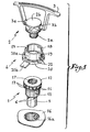
- the shutter 1 illustrated in fig. 1 has been described in document FR-A-1 330 155 of the present Applicant and therefore does not have to be described in detail. However and as illustrated in fig. 2, it includes a bottom 5 provided with perforations 6 and a bore 8. Its upper part has a flange 7 crimped relative to the shutter 1. In the bore 8 of the bottom 5 is arranged a ball 9 loaded by a spring 10 in the direction of a seat 11, so that the gas contained in the tank cannot escape until the ball 9 is pressed.
- the upper part of the shutter 1 is produced under the form a flange 12, the periphery of which is hollowed out with notches 13 fifteen in number and which are separated by zones 14 representing portions of the cylinder.
- the plug 2 comprises a threaded body 2a and a head 2b with respect to which a handle 3 is articulated by means of two diametrically opposite pins 3a, 3b which engage in corresponding holes in said head so that the handle can pivot around of a transverse axis relative to this head 2b.
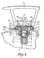
- the capsule according to the invention comprises first of all a tubular sleeve 18 with a smooth inner face and which is provided with two diametrically opposite notches 19 open towards its free edge.
- the inside diameter of the sleeve 18 is at play nearly equal to that of the head 2b, so that it can be easily engaged inside the sleeve with its pins placed at the bottom of the notches 19 whose width corresponds to the play to the diameter of each pin.
- the capsule 4 also has a ring 20 of larger diameter than the sleeve 18, so that between its internal wall 20a and the external wall of the sleeve 18 is a space in which is formed a zone of least resistance 21 connecting the ring and the sleeve 18.
- This zone of least resistance is produced by means of teeth 22 coming from the internal face 20a of the ring 20 and which extend over the entire height of the latter. As illustrated in fig. 3, the teeth are inclined, that is to say that they have a triangular shape in profile in plan.
- One of their faces 22a is normally oriented to the wall 20a of the ring 20, while their other face 22b is oblique.
- This oblique face is oriented in such a way that during the screwing of the stopper and the capsule, the oblique faces attack the edges of the notches 13 and jump them in the manner of a ratchet relative to a ratchet wheel, the latter being represented by the notches 13 and the zones 14 of the periphery of the flange 12.
- the ring also has a tab 20b intended to receive an identification or marking engraving.
- the teeth of one series are angularly offset with respect to those of the other series by an angle equal to half the angle determined by two successive notches 13 of the shutter 1.
- C ' is thus that the teeth 22 of one series are offset by 9 ° relative to those of the other series if there are 20 notches on the flange 12 of the shutter 1 (notches offset by 18 °).
- the teeth 22 cooperate over the entire height of the ring 20 with the inner face of the latter. On the contrary, the assembly of the sleeve 18 and of these teeth is carried out only on the end of the latter. As the ends of the teeth are pointed and their sharp edges 22c are oblique, the common area between the teeth 22 and the sleeve 18 is extremely reduced (FIGS. 6 and 7).
- a tamper-evident capsule was thus produced comprising the desired characteristics. Indeed, it tears during the operation of unscrewing the plug 1 so that it is no longer reusable. It can be easily produced by injection molding, but it is nevertheless necessary to have a tool to make it. expensive which is beyond the reach of those who usually fill tanks unauthorized. Finally, it mounts automatically during the closing operation of the reservoir once it has been filled. And above all, the capsule according to the invention, by being compatible with existing closures, avoids replacing them with new closures incorporating the sought-after tamper-evident function.
Abstract
Description
La présente invention concerne une capsule assurant l'authenticité du contenu d'un réservoir renfermant notamment un gaz de pétrole liquéfié tel que du butane, et pourvu d'un obturateur comportant un alésage central dans lequel est disposé un clapet de retenue et qui débouche à l'extérieur par une partie taraudée destinée à recevoir un bouchon avec poignée de transport, lequel au moment de l'utilisation est démonté et remplacé par une tête de prise de gaz destinée à l'alimentation d'un appareil quelconque. Une partie de l'obturateur dépasse hors du réservoir et sa périphérie comporte une série de crans qui sont, dans la technique actuelle, destinés à permettre la mise en place et le serrage de l'obturateur dans un trou taraudé ménagé dans le réservoir. Un tel obturateur est décrit dans le document FR-A-1 330 155.The present invention relates to a capsule ensuring the authenticity of the contents of a tank containing in particular a liquefied petroleum gas such as butane, and provided with a shutter comprising a central bore in which is arranged a check valve and which opens out to the outside by a threaded part intended to receive a plug with transport handle, which at the time of use is dismantled and replaced by a gas intake head intended for the supply of any device. Part of the shutter protrudes out of the tank and its periphery comprises a series of notches which are, in the current technique, intended to allow the fitting and tightening of the shutter in a tapped hole in the tank. Such a shutter is described in document FR-A-1 330 155.
Actuellement, pour empêcher le remplissage non autorisé des réservoirs de gaz liquéfié du type concerné et pour garantir au consommateur la fiabilité et la sécurité dudit réservoir ainsi que l'origine de la charge de gaz, on applique sur sa zone entourant l'obturateur une bande adhésive de garantie qui traverse la poignée du bouchon. La présence d'une telle bande ne garantit pas absolument les consommateurs que le réservoir n'a pas été rempli illégalement par des tiers non autorisés. Ainsi les bandes de garantie du genre actuellement utilisées peuvent, si l'on prend des précautions, être détachées du réservoir sans être rompues, de sorte qu'elles peuvent être réutilisées abusivement. En outre, les bandes de ce type peuvent être imprimées assez facilement et à un prix de revient assez bas par des contrefacteurs.Currently, to prevent unauthorized filling of liquefied gas tanks of the type concerned and to guarantee the consumer the reliability and safety of said tank as well as the origin of the gas charge, a band is applied to its area surrounding the shutter. Guarantee adhesive which passes through the handle of the cap. The presence of such a strip does not absolutely guarantee consumers that the tank has not been unlawfully filled by unauthorized third parties. Thus the guarantee bands of the kind currently used can, if precautions are taken, be detached from the tank without being broken, so that they can be reused improperly. In addition, tapes of this type can be printed fairly easily and at a fairly low cost price by counterfeiters.
Les perfectionnements qui font l'objet de la présente invention visent à remédier aux inconvénients précités des bandes de garantie et à permettre de réaliser un dispositif de protection susceptible d'assurer aux consommateurs que le réservoir qu'ils ont acheté n'a pas été rempli illégalement. Dans ce but, le dispositif de protection selon l'invention doit présenter des caractéristiques bien précises et en particulier : il doit se rompre consécutivement au dévissage du bouchon du réservoir de telle sorte qu'il soit détruit et ne puisse plus être utilisé ; il ne doit pas pouvoir être aisément reproduit par les personnes qui peuvent normalement être amenées à remplir illégitimement les réservoirs ; enfin il doit avantageusement pouvoir être monté de manière automatique sur les réservoirs normaux existants.The improvements which are the subject of the present invention aim to remedy the aforementioned drawbacks of the guarantee strips and to make it possible to produce a protection device capable of assuring consumers that the tank they have purchased has not been filled. illegally. For this purpose, the protection device according to the invention must have very specific characteristics and in particular: it must break following the unscrewing of the cap of the tank so that it is destroyed and can no longer be used; it must not be able to be easily reproduced by persons who may normally have to fill tanks illegally; finally it must advantageously be able to be mounted automatically on existing normal tanks.
On connaît le document FR-A-1 381 270 qui décrit une capsule de bouchage inviolable en matière plastique constituée de deux parties séparées par une zone de moindre résistance de la matière plastique. La partie supérieure est pourvue de filets internes coopérant avec le pas de vis d'un goulot d'une bouteille, tandis que la partie inférieure, établie sous la forme d'une bague, comporte sur sa face interne des lamelles flexibles convenablement inclinées, de telle sorte qu'elles sont susceptibles de se replier au cours du vissage de la capsule, en s'effaçant au passage de rampes successives ménagées sur l'extérieur du goulot considéré. Lors du dévissage, les lamelles butent contre les pans coupés déterminés par chaque rampe avec sa voisine, interdisant ainsi toute violation de la capsule par dévissage, car cette opération provoque la rupture de la zone de moindre résistance.Document FR-A-1 381 270 is known which describes a tamper-evident plastic closure cap made up of two parts separated by a zone of reduced resistance of the plastic material. The upper part is provided with internal threads cooperating with the thread of a neck of a bottle, while the lower part, established in the form of a ring, has on its internal face flexible strips suitably inclined, of such that they are liable to fold back during the screwing of the capsule, by disappearing in the passage of successive ramps formed on the outside of the neck considered. When unscrewing, the slats abut against the cut sides determined by each ramp with its neighbor, thus preventing any violation of the capsule by unscrewing, because this operation causes the rupture of the zone of least resistance.
Conformément à la présente invention, pour obtenir une capsule inviolable du genre de celle décrite dans le document ci-dessus, on utilise les encoches radiales portées par la périphérie ou crans de la partie dépassante de l'obturateur du réservoir et les zones périphériques qui les séparent à titre de pans coupés tels que ceux décrits dans le document français FR-A-1 381 270.In accordance with the present invention, to obtain a tamper-evident capsule of the kind described in the document above, use is made of the radial notches carried by the periphery or notches of the protruding part of the obturator of the reservoir and the peripheral zones which separate as cut sections such as those described in French document FR-A-1 381 270.
Le problème posé, en ce qui concerne la protection du contenu des réservoirs de gaz liquide, ne consiste pas à éviter le dévissage d'une capsule, mais à ne pas permettre celui d'un bouchon métallique vissé dans l'alésage taraudé de l'obturateur, ledit bouchon étant pourvu d'une poignée articulée à lui au moyen de deux tourillons diamétralement opposés.The problem posed, as regards the protection of the contents of the liquid gas tanks, does not consist in avoiding the unscrewing of a capsule, but in not allowing that of a metal plug screwed into the threaded bore of the shutter, said plug being provided with a handle articulated to it by means of two diametrically opposite pins.
La capsule de protection suivant l'invention, réalisée en matière plastique, comprend un manchon tubulaire pour enserrer la tête du bouchon en soi connu auquel la poignée est associée au moyen de deux tourillons diamétralement opposés, ledit manchon étant pourvu d'encoches ouvertes vers le haut disposées de manière diamétralement opposée afin que les tourillons les traversent, tandis que les lamelles sont destinées à coopérer avec les crans extérieurs de l'obturateur usuel dans lequel se visse le bouchon, de telle sorte que le dévissage de la poignée provoque la rotation du manchon et la rupture de la zone de moindre résistance, du fait que la bague reste angulairement fixe.The protective capsule according to the invention, produced in plastic material, comprises a tubular sleeve for enclosing the head of the plug per se known with which the handle is associated by means of two diametrically opposite pins, said sleeve being provided with notches open upwards arranged in a diametrically opposite manner so that the pins pass through, while the strips are intended to cooperate with the external notches of the usual shutter into which the plug is screwed, so that unscrewing the handle causes the rotation of the sleeve and the rupture of the zone of least resistance, because the ring remains angularly fixed.
Ainsi, un utilisateur en présence d'un réservoir pourvu d'une capsule déchirée peut-il douter de l'authenticité de son contenu.Thus, a user in the presence of a reservoir provided with a torn capsule can doubt the authenticity of its content.
Suivant un mode d'exécution préféré de la disposition qui précède, les lamelles sont réalisées sous la forme de petites dents inclinées, de manière que chacune d'elles fonctionne à la manière d'un cliquet par rapport à une roue à rochet qui est représentée par la périphérie crantée de la partie de l'obturateur située hors du réservoir.According to a preferred embodiment of the above arrangement, the slats are made in the form of small inclined teeth, so that each of them operates in the manner of a pawl relative to a ratchet wheel which is shown by the notched periphery of the part of the shutter located outside the tank.
Suivant une disposition avantageuse, les dents inclinées sont réparties en deux séries diamétralement opposées déterminant entre elles deux espaces libres importants. Comme les crans de la périphérie de l'obturateur sont en nombre impair, aucun d'eux ne se trouve diamétralement opposé par rapport à un autre, de telle sorte qu'en fin de vissage de bouchon, si une série de dents se trouve engagée dans une série correspondante de crans, l'autre série de dents se trouve en appui sur la zone périphérique de la collerette de l'obturateur séparant les crans successifs.According to an advantageous arrangement, the inclined teeth are distributed in two diametrically opposite series determining between them two large free spaces. As the notches of the periphery of the shutter are in odd number, none of them is diametrically opposite with respect to another, so that at the end of screwing in the cap, if a series of teeth is engaged in a corresponding series of notches, the other series of teeth is supported on the peripheral zone of the flange of the shutter separating the successive notches.
Le dessin annexé, donné à titre d'exemple, permettra de mieux comprendre l'invention, les caractéristiques qu'elle présente et les avantages qu'elle est susceptible de procurer :
- Fig. 1 est une vue éclatée montrant l'obturateur usuel d'un réservoir de gaz sous pression et son bouchon muni d'une poignée de manoeuvre et de portage, ainsi qu'une capsule établie conformément à l'invention.
- Fig. 2 montre le bouchon à l'état monté dans l'obturateur d'un réservoir, la capsule suivant l'invention étant inserrée entre eux.
- Fig. 3 est une vue par dessous d'une capsule établie conformément à l'invention.
- Fig. 4 est une vue semblable à celle de fig. 3, mais montrant la capsule associée à la collerette de l'obturateur du réservoir.
- Fig. 5 illustre à plus grande échelle la capsule suivant l'invention associée au bouchon avant la mise en place de celui-ci dans l'obturateur du réservoir.
- Fig. 6 est une vue semblable à celle de fig. 5, mais montrant les pièces au moment de la fin du vissage du bouchon.
- Fig. 7 est une vue semblable à celle de fig. 6, mais montrant la capsule déchirée après le début du dévissage du bouchon.
- Fig. 1 is an exploded view showing the usual shutter of a pressurized gas tank and its cap provided with an operating and carrying handle, as well as a capsule established in accordance with the invention.
- Fig. 2 shows the cap in the state mounted in the shutter of a reservoir, the capsule according to the invention being inserted between them.
- Fig. 3 is a view from below of a capsule established in accordance with the invention.
- Fig. 4 is a view similar to that of FIG. 3, but showing the capsule associated with the collar of the tank shutter.
- Fig. 5 illustrates on a larger scale the capsule according to the invention associated with the stopper before the latter is put into place in the shutter of the reservoir.
- Fig. 6 is a view similar to that of FIG. 5, but showing the parts at the end of the screwing of the cap.
- Fig. 7 is a view similar to that of FIG. 6, but showing the torn capsule after the beginning of the unscrewing of the cap.
L'obturateur 1 illustré en fig. 1 a été décrit dans le document FR-A-1 330 155 de la présente Demanderesse et n'a donc pas à être décrit de manière détaillée. Toutefois et comme illustré en fig. 2, il comprend un fond 5 pourvu de perforations 6 et d'un alésage 8. Sa partie supérieure comporte une bride 7 sertie par rapport à l'obturateur 1. Dans l'alésage 8 du fond 5 est disposée une bille 9 chargée par un ressort 10 en direction d'un siège 11, de telle manière que le gaz contenu par le réservoir ne puisse pas s'échapper tant qu'on n'appuie pas sur la bille 9. La partie supérieure de l'obturateur 1 est réalisée sous la forme d'une collerette 12 dont la périphérie est creusée de crans 13 au nombre de quinze et qui sont séparés par des zones 14 représentant des portions de cylindre.The
Le bouchon 2 comporte un corps fileté 2a et une tête 2b par rapport à laquelle une poignée 3 est articulée au moyen de deux tourillons diamétralement opposés 3a, 3b qui s'engagent dans des trous correspondants de ladite tête de manière que la poignée puisse pivoter autour d'un axe transversal par rapport à cette tête 2b.The
La capsule suivant l'invention comporte tout d'abord un manchon tubulaire 18 à face intérieure lisse et qui est pourvu de deux encoches 19 diamétralement opposées ouvertes en direction de son arête libre. Le diamètre intérieur du manchon 18 est au jeu près égal à celui de la tête 2b, de manière que celle-ci puisse être engagée facilement à l'intérieur du manchon avec ses tourillons placés au fond des encoches 19 dont la largeur correspond au jeu près au diamètre de chaque tourillon.The capsule according to the invention comprises first of all a
La capsule 4 comporte encore une bague 20 de plus grand diamètre que le manchon 18, de telle sorte qu'entre sa paroi interne 20a et la paroi externe du manchon 18 se trouve un espace dans lequel est constituée une zone de moindre résistance 21 reliant la bague et le manchon 18. Cette zone de moindre résistance est réalisée au moyen de dents 22 issues de la face interne 20a de la bague 20 et qui s'étendent sur toute la hauteur de celle-ci. Comme illustré en fig. 3, les dents sont inclinées, c'est-à-dire qu'elles ont une forme triangulaire en profil en plan. L'une 22a de leurs faces se trouve orientée normalement à la paroi 20a de la bague 20, tandis que leur autre face 22b est oblique. Cette face oblique se trouve orientée de telle manière que lors du vissage du bouchon et de la capsule, les faces obliques attaquent les arêtes des crans 13 et les sautent à la manière d'un cliquet par rapport à une roue à rochet, cette dernière étant représentée par les crans 13 et les zones 14 de la périphérie de la collerette 12. Au contraire, lors du dévissage, c'est la face normale 22a de chaque dent qui vient porter contre la face latérale correspondante de chaque cran 13. On observe que la bague comporte encore une patte 20b destinée à recevoir une gravure d'identification ou marquage.The
Comme on peut l'observer sur la fig. 3, il existe deux séries de dents 22, chacune en comportant six. Ces dents se trouvent de manière diamétralement opposées les unes par rapport aux autres. Etant donné qu'il y a quinze crans 13, ceux-ci sont séparés d'un angle de 24°, tant et si bien qu'aucun d'eux ne se trouve diamétralement opposé à un autre, mais au contraire qu'ils présentent entre eux un décalage de douze degrés. Ainsi, en fin de vissage, les dents 22 d'une série tombent dans le nombre correspondant de crans 13, tandis que les dents de l'autre série restent en appui contre les zones 14 de la périphérie de la collerette 12 situées entre les crans 13. Ainsi, on est assuré qu'en fin de vissage du bouchon 2 dans l'obturateur 1, les dents d'une série se trouvent orientées dans le plus mauvais des cas suivant un angle de 12° par rapport aux crans 13. Ainsi, au cas ou quelqu'un essaierait de dévisser le bouchon, dans ces conditions, celui-ci n'effectuerait qu'un déplacement angulaire de 12° au maximum, avant que les dents 22 d'une des deux séries ne tombent dans les crans correspondants 13. Un tel déplacement angulaire n'entraîne aucun desserrage substantiel du bouchon, un tel desserrage n'ayant aucune influence sur la fermeture du réservoir, puisqu'en fait l'étanchéité n'est pas faite au niveau de ce bouchon, mais à celui de la bille 9 dans l'obturateur 1.As can be seen in fig. 3, there are two sets of
Suivant une réalisation avantageuse et plus générale les dents d'une série sont angulairement décalées par rapport à celles de l'autre série d'un angle égal à la moitié de l'angle déterminé par deux crans successifs 13 de l'obturateur 1. C'est ainsi que les dents 22 d'une série sont décalées de 9° par rapport à celles de l'autre série s'il y a 20 crans sur la collerette 12 de l'obturateur 1 (crans décalés de 18°).According to an advantageous and more general embodiment, the teeth of one series are angularly offset with respect to those of the other series by an angle equal to half the angle determined by two
Les dents 22 coopèrent sur toute la hauteur de la bague 20 avec la face intérieure de celle-ci. Au contraire, l'assemblage du manchon 18 et de ces dents ne s'effectue que sur l'extrémité de celles-ci. Comme les extrémités des dents sont pointues et que leurs arêtes vives 22c sont obliques, la surface commune entre les dents 22 et le manchon 18 est extrêmement réduite (fig. 6 et 7).The
La mise en place sur un réservoir s'effectue de la manière suivante :
- De manière automatique, le
bouchon 2 est engagé dans lacapsule 4 suivant une certaine orientation afin que lestourillons poignée 3 pénètrent dans les encoches 19 (fig. 5). Puis, au moyen d'un mandrin approprié, l'ensemble de la capsule et du bouchon est amené au-dessus de l'alésage taraudé 17 de l'obturateur 1. Le mandrin est mis en rotation de manière que le bouchon 2 se visse dans ledit alésage. En fin de course de vissage, les pièces 1, 2et 4 occupent la position illustrée en fig. 2.
- Automatically, the
plug 2 is engaged in thecapsule 4 in a certain orientation so that thepins handle 3 penetrate into the notches 19 (fig. 5). Then, by means of a suitable mandrel, the whole of the capsule and the plug is brought above the threaded bore 17 of theshutter 1. The mandrel is rotated so that theplug 2 is screwed in said bore. At the end of the screwing stroke, theparts
Lorsqu'un utilisateur veut avoir accès au gaz contenu dans le réservoir 16, il dévisse le bouchon en prenant en main la poignée 3. Les faces 22a des dents viennent buter contre la face latérale correspondante des crans 13, de sorte que la bague 20 est immobilisée en rotation par rapport à la collerette 12 de l'obturateur 1. L'effort de dévissage qui entraîne la rotation de la bague 18 de la capsule 4 produit la rupture des liaisons très faibles existant entre les dents 22 et le manchon 18 comme illustré en fig. 7, de telle sorte qu'alors ce dernier et la bague 20 sont séparés de manière visible.When a user wants to have access to the gas contained in the
On a ainsi réalisé une capsule d'inviolabilité comportant les caractéristiques désirées. En effet, elle se déchire lors de l'opération de dévissage du bouchon 1 de manière qu'elle ne soit plus réutilisable. Elle peut être facilement réalisée par moulage par injection, mais il est néanmoins nécessaire de disposer pour la fabriquer d'un outillage coûteux qui n'est pas à la portée de ceux qui remplissent habituellement les réservoirs de manière non autorisée. Elle se monte enfin de manière automatique pendant l'opération de fermeture du réservoir une fois celui-ci rempli. Et surtout, la capsule selon l'invention, en étant compatible avec les bouchons existants, évite de leur substituer de nouveaux bouchons incorporant la fonction d'inviolabilité recherchée.A tamper-evident capsule was thus produced comprising the desired characteristics. Indeed, it tears during the operation of unscrewing the
Claims (5)
Applications Claiming Priority (1)
| Application Number | Priority Date | Filing Date | Title |
|---|---|---|---|
| IT2191284U IT206006Z2 (en) | 1984-05-25 | 1984-05-25 | GUARANTEE CAPSULE AGAINST ABUSIVE FILLING OF LIQUID GAS CYLINDERS HAVING A HEAD WITH SEALING VALVE AND THREADED HOLE RESPECTIVELY FOR A CAP WITH TRANSPORT HANDLE AND A GAS SOCKET. |
Publications (2)
| Publication Number | Publication Date |
|---|---|
| EP0166664A2 true EP0166664A2 (en) | 1986-01-02 |
| EP0166664A3 EP0166664A3 (en) | 1986-02-26 |
Family
ID=11188658
Family Applications (1)
| Application Number | Title | Priority Date | Filing Date |
|---|---|---|---|
| EP85420100A Withdrawn EP0166664A3 (en) | 1984-05-25 | 1985-05-24 | Plastic protecting capsule |
Country Status (5)
| Country | Link |
|---|---|
| EP (1) | EP0166664A3 (en) |
| DK (1) | DK233085A (en) |
| ES (1) | ES286980Y (en) |
| IT (1) | IT206006Z2 (en) |
| PT (1) | PT80503A (en) |
Cited By (4)
| Publication number | Priority date | Publication date | Assignee | Title |
|---|---|---|---|---|
| GR880100009A (en) * | 1987-01-15 | 1988-12-16 | Applic Gaz Sa | Protective cap intended for safeguarding the closing of a stopper |
| EP0324196A2 (en) * | 1988-01-11 | 1989-07-19 | Rieke Corporation | Tamper-evident buttress plug closure |
| EP1437560A1 (en) * | 2003-01-07 | 2004-07-14 | Behr Lorraine S.A.R.L. | Protective cap for an air conditioner collection vessel |
| EP1626373A1 (en) * | 2004-08-10 | 2006-02-15 | LA BOITA S.r.l. | Coin-operated lock for supermarket carts, luggage trolleys and the like |
Citations (2)
| Publication number | Priority date | Publication date | Assignee | Title |
|---|---|---|---|---|
| FR1330155A (en) * | 1962-03-01 | 1963-06-21 | Applic Gaz Sa | Refinements to poppet valves |
| FR1435928A (en) * | 1965-03-08 | 1966-04-22 | Pierre Remy Et Cie Ets | Seal guaranteeing the closure of a container |
-
1984
- 1984-05-25 IT IT2191284U patent/IT206006Z2/en active
-
1985
- 1985-05-21 PT PT8050385A patent/PT80503A/en unknown
- 1985-05-23 ES ES1985286980U patent/ES286980Y/en not_active Expired
- 1985-05-24 EP EP85420100A patent/EP0166664A3/en not_active Withdrawn
- 1985-05-24 DK DK233085A patent/DK233085A/en not_active Application Discontinuation
Patent Citations (2)
| Publication number | Priority date | Publication date | Assignee | Title |
|---|---|---|---|---|
| FR1330155A (en) * | 1962-03-01 | 1963-06-21 | Applic Gaz Sa | Refinements to poppet valves |
| FR1435928A (en) * | 1965-03-08 | 1966-04-22 | Pierre Remy Et Cie Ets | Seal guaranteeing the closure of a container |
Cited By (7)
| Publication number | Priority date | Publication date | Assignee | Title |
|---|---|---|---|---|
| GR880100009A (en) * | 1987-01-15 | 1988-12-16 | Applic Gaz Sa | Protective cap intended for safeguarding the closing of a stopper |
| EP0324196A2 (en) * | 1988-01-11 | 1989-07-19 | Rieke Corporation | Tamper-evident buttress plug closure |
| EP0324196A3 (en) * | 1988-01-11 | 1990-08-01 | Rieke Corporation | Tamper-evident buttress plug closure |
| EP1437560A1 (en) * | 2003-01-07 | 2004-07-14 | Behr Lorraine S.A.R.L. | Protective cap for an air conditioner collection vessel |
| WO2004061376A1 (en) * | 2003-01-07 | 2004-07-22 | Behr Lorraine S.A.R.L. | Protective cap for a sealing stopper on a container for a capacitor |
| US7334607B2 (en) | 2003-01-07 | 2008-02-26 | Behr France Hambach | Protective cap for a sealing stopper in a collecting vessel of a condenser |
| EP1626373A1 (en) * | 2004-08-10 | 2006-02-15 | LA BOITA S.r.l. | Coin-operated lock for supermarket carts, luggage trolleys and the like |
Also Published As
| Publication number | Publication date |
|---|---|
| PT80503A (en) | 1985-06-01 |
| IT206006Z2 (en) | 1987-03-02 |
| IT8421912V0 (en) | 1984-05-25 |
| ES286980U (en) | 1985-12-16 |
| EP0166664A3 (en) | 1986-02-26 |
| ES286980Y (en) | 1986-07-16 |
| DK233085A (en) | 1985-11-26 |
| DK233085D0 (en) | 1985-05-24 |
Similar Documents
| Publication | Publication Date | Title |
|---|---|---|
| EP3741703B1 (en) | Screw cap intended to remain attached to a container after opening of the container | |
| EP0244327B1 (en) | Container spout provided with means for preventing refilling after dispensing with the initial contents | |
| EP0641721A1 (en) | Screwcap with tamper evidence band, package provided with such a cap, method of making such a cap and such a package | |
| FR2553737A1 (en) | CHILD RESISTANT CLOSURE AND INDICATION OF SPOLIATION | |
| EP0166664A2 (en) | Plastic protecting capsule | |
| LU88070A1 (en) | SEAL FOR BOTTLE CAPS | |
| FR3108317A3 (en) | CAP FOR CONTAINER WITH THREADED NECK EQUIPPED WITH A LOCKING BODY BY ENGAGEMENT | |
| FR3096361A1 (en) | Screw cap intended to remain attached to a container after opening the container. | |
| FR2663300A1 (en) | Valve cap with safety ring for bottles and other containers | |
| EP0794129A1 (en) | Closure for a container, particularlyfor a medical vial | |
| FR2701010A1 (en) | Clogging device with irreversible unscrewing. | |
| EP3984906B1 (en) | Screw cap intended to remain attached to a container after opening and which can be held in an open position | |
| EP3984905B1 (en) | Screw cap intended to remain attached to a container after opening, containing in particular an effervescent liquid | |
| FR2647185A1 (en) | Security capsule for gas cylinders before they are first opened | |
| FR2779702A1 (en) | Tamper proof cap for bottles such as a medicine bottle | |
| EP0045708B1 (en) | Security cap for the tamper-proof fastening of non refillable stoppers for bottles and other containers | |
| FR2996534A1 (en) | Capsule for bottle utilized in e.g. pharmacy field, has body with anti-return notches, hinged cover to seal body, and safety unit cooperating with complementary unit provided by body, where safety unit is arranged for opening of cover | |
| EP1311439B1 (en) | Closure comprising means for locking radial deformation of the tamperproof band | |
| EP4005945B1 (en) | Assembly comprising a container and a closure device attached to the container | |
| EP4026783B1 (en) | Sealing device intended to be attached to the neck of a container | |
| CH669368A5 (en) | Protective cap for gas bottle - guarantees closure of obturator with externally notched collar into which stopper is screwed with handle arms projecting through slots | |
| FR2778643A1 (en) | Tamperproof device especially for bottle cap of synthetic material | |
| WO2003011703A1 (en) | Container closure cap and neck preventing self-unscrewing of the closure cap under the effect of internal pressure in the container | |
| FR1389177A (en) | Improvements to tamper-proof closing devices for crown ring necks | |
| FR2842177A1 (en) | Stopper with hinged cap comprises base and cap with top cover articulated to ring by strap enabling cap to be molded in closed position |
Legal Events
| Date | Code | Title | Description |
|---|---|---|---|
| PUAI | Public reference made under article 153(3) epc to a published international application that has entered the european phase |
Free format text: ORIGINAL CODE: 0009012 |
|
| AK | Designated contracting states |
Designated state(s): AT BE CH DE FR GB IT LI LU NL SE |
|
| PUAL | Search report despatched |
Free format text: ORIGINAL CODE: 0009013 |
|
| AK | Designated contracting states |
Designated state(s): AT BE CH DE FR GB IT LI LU NL SE |
|
| RBV | Designated contracting states (corrected) |
Designated state(s): AT BE CH DE FR GB IT LI NL |
|
| STAA | Information on the status of an ep patent application or granted ep patent |
Free format text: STATUS: THE APPLICATION IS DEEMED TO BE WITHDRAWN |
|
| 18D | Application deemed to be withdrawn |
Effective date: 19861028 |
|
| RIN1 | Information on inventor provided before grant (corrected) |
Inventor name: GIACOBELLI, FABIO |