EP0166664A2 - Schutzkapsel aus Kunststoffmaterial - Google Patents
Schutzkapsel aus Kunststoffmaterial Download PDFInfo
- Publication number
- EP0166664A2 EP0166664A2 EP85420100A EP85420100A EP0166664A2 EP 0166664 A2 EP0166664 A2 EP 0166664A2 EP 85420100 A EP85420100 A EP 85420100A EP 85420100 A EP85420100 A EP 85420100A EP 0166664 A2 EP0166664 A2 EP 0166664A2
- Authority
- EP
- European Patent Office
- Prior art keywords
- teeth
- notches
- series
- shutter
- capsule
- Prior art date
- Legal status (The legal status is an assumption and is not a legal conclusion. Google has not performed a legal analysis and makes no representation as to the accuracy of the status listed.)
- Withdrawn
Links
Images


Classifications
-
- F—MECHANICAL ENGINEERING; LIGHTING; HEATING; WEAPONS; BLASTING
- F17—STORING OR DISTRIBUTING GASES OR LIQUIDS
- F17C—VESSELS FOR CONTAINING OR STORING COMPRESSED, LIQUEFIED OR SOLIDIFIED GASES; FIXED-CAPACITY GAS-HOLDERS; FILLING VESSELS WITH, OR DISCHARGING FROM VESSELS, COMPRESSED, LIQUEFIED, OR SOLIDIFIED GASES
- F17C13/00—Details of vessels or of the filling or discharging of vessels
- F17C13/06—Closures, e.g. cap, breakable member
-
- B—PERFORMING OPERATIONS; TRANSPORTING
- B65—CONVEYING; PACKING; STORING; HANDLING THIN OR FILAMENTARY MATERIAL
- B65D—CONTAINERS FOR STORAGE OR TRANSPORT OF ARTICLES OR MATERIALS, e.g. BAGS, BARRELS, BOTTLES, BOXES, CANS, CARTONS, CRATES, DRUMS, JARS, TANKS, HOPPERS, FORWARDING CONTAINERS; ACCESSORIES, CLOSURES, OR FITTINGS THEREFOR; PACKAGING ELEMENTS; PACKAGES
- B65D55/00—Accessories for container closures not otherwise provided for
- B65D55/02—Locking devices; Means for discouraging or indicating unauthorised opening or removal of closure
- B65D55/022—Locking devices; Means for discouraging or indicating unauthorised opening or removal of closure with ratchet effect between relatively rotating parts
-
- F—MECHANICAL ENGINEERING; LIGHTING; HEATING; WEAPONS; BLASTING
- F17—STORING OR DISTRIBUTING GASES OR LIQUIDS
- F17C—VESSELS FOR CONTAINING OR STORING COMPRESSED, LIQUEFIED OR SOLIDIFIED GASES; FIXED-CAPACITY GAS-HOLDERS; FILLING VESSELS WITH, OR DISCHARGING FROM VESSELS, COMPRESSED, LIQUEFIED, OR SOLIDIFIED GASES
- F17C2205/00—Vessel construction, in particular mounting arrangements, attachments or identifications means
- F17C2205/03—Fluid connections, filters, valves, closure means or other attachments
- F17C2205/0302—Fittings, valves, filters, or components in connection with the gas storage device
- F17C2205/0308—Protective caps
-
- F—MECHANICAL ENGINEERING; LIGHTING; HEATING; WEAPONS; BLASTING
- F17—STORING OR DISTRIBUTING GASES OR LIQUIDS
- F17C—VESSELS FOR CONTAINING OR STORING COMPRESSED, LIQUEFIED OR SOLIDIFIED GASES; FIXED-CAPACITY GAS-HOLDERS; FILLING VESSELS WITH, OR DISCHARGING FROM VESSELS, COMPRESSED, LIQUEFIED, OR SOLIDIFIED GASES
- F17C2205/00—Vessel construction, in particular mounting arrangements, attachments or identifications means
- F17C2205/05—Vessel or content identifications, e.g. labels
-
- F—MECHANICAL ENGINEERING; LIGHTING; HEATING; WEAPONS; BLASTING
- F17—STORING OR DISTRIBUTING GASES OR LIQUIDS
- F17C—VESSELS FOR CONTAINING OR STORING COMPRESSED, LIQUEFIED OR SOLIDIFIED GASES; FIXED-CAPACITY GAS-HOLDERS; FILLING VESSELS WITH, OR DISCHARGING FROM VESSELS, COMPRESSED, LIQUEFIED, OR SOLIDIFIED GASES
- F17C2270/00—Applications
- F17C2270/07—Applications for household use
- F17C2270/0736—Capsules, e.g. CO2
Definitions
- the present invention relates to a capsule ensuring the authenticity of the contents of a tank containing in particular a liquefied petroleum gas such as butane, and provided with a shutter comprising a central bore in which is arranged a check valve and which opens out to the outside by a threaded part intended to receive a plug with transport handle, which at the time of use is dismantled and replaced by a gas intake head intended for the supply of any device.
- Part of the shutter protrudes out of the tank and its periphery comprises a series of notches which are, in the current technique, intended to allow the fitting and tightening of the shutter in a tapped hole in the tank.
- a shutter is described in document FR-A-1 330 155.
- the improvements which are the subject of the present invention aim to remedy the aforementioned drawbacks of the guarantee strips and to make it possible to produce a protection device capable of assuring consumers that the tank they have purchased has not been filled. illegally.
- the protection device according to the invention must have very specific characteristics and in particular: it must break following the unscrewing of the cap of the tank so that it is destroyed and can no longer be used; it must not be able to be easily reproduced by persons who may normally have to fill tanks illegally; finally it must advantageously be able to be mounted automatically on existing normal tanks.
- Document FR-A-1 381 270 which describes a tamper-evident plastic closure cap made up of two parts separated by a zone of reduced resistance of the plastic material.
- the upper part is provided with internal threads cooperating with the thread of a neck of a bottle, while the lower part, established in the form of a ring, has on its internal face flexible strips suitably inclined, of such that they are liable to fold back during the screwing of the capsule, by disappearing in the passage of successive ramps formed on the outside of the neck considered.
- unscrewing the slats abut against the cut sides determined by each ramp with its neighbor, thus preventing any violation of the capsule by unscrewing, because this operation causes the rupture of the zone of least resistance.
- the problem posed, as regards the protection of the contents of the liquid gas tanks, does not consist in avoiding the unscrewing of a capsule, but in not allowing that of a metal plug screwed into the threaded bore of the shutter, said plug being provided with a handle articulated to it by means of two diametrically opposite pins.
- the protective capsule according to the invention produced in plastic material, comprises a tubular sleeve for enclosing the head of the plug per se known with which the handle is associated by means of two diametrically opposite pins, said sleeve being provided with notches open upwards arranged in a diametrically opposite manner so that the pins pass through, while the strips are intended to cooperate with the external notches of the usual shutter into which the plug is screwed, so that unscrewing the handle causes the rotation of the sleeve and the rupture of the zone of least resistance, because the ring remains angularly fixed.
- the slats are made in the form of small inclined teeth, so that each of them operates in the manner of a pawl relative to a ratchet wheel which is shown by the notched periphery of the part of the shutter located outside the tank.
- the inclined teeth are distributed in two diametrically opposite series determining between them two large free spaces.
- the notches of the periphery of the shutter are in odd number, none of them is diametrically opposite with respect to another, so that at the end of screwing in the cap, if a series of teeth is engaged in a corresponding series of notches, the other series of teeth is supported on the peripheral zone of the flange of the shutter separating the successive notches.
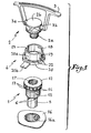
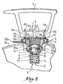
- the shutter 1 illustrated in fig. 1 has been described in document FR-A-1 330 155 of the present Applicant and therefore does not have to be described in detail. However and as illustrated in fig. 2, it includes a bottom 5 provided with perforations 6 and a bore 8. Its upper part has a flange 7 crimped relative to the shutter 1. In the bore 8 of the bottom 5 is arranged a ball 9 loaded by a spring 10 in the direction of a seat 11, so that the gas contained in the tank cannot escape until the ball 9 is pressed.
- the upper part of the shutter 1 is produced under the form a flange 12, the periphery of which is hollowed out with notches 13 fifteen in number and which are separated by zones 14 representing portions of the cylinder.
- the plug 2 comprises a threaded body 2a and a head 2b with respect to which a handle 3 is articulated by means of two diametrically opposite pins 3a, 3b which engage in corresponding holes in said head so that the handle can pivot around of a transverse axis relative to this head 2b.
- the capsule according to the invention comprises first of all a tubular sleeve 18 with a smooth inner face and which is provided with two diametrically opposite notches 19 open towards its free edge.
- the inside diameter of the sleeve 18 is at play nearly equal to that of the head 2b, so that it can be easily engaged inside the sleeve with its pins placed at the bottom of the notches 19 whose width corresponds to the play to the diameter of each pin.
- the capsule 4 also has a ring 20 of larger diameter than the sleeve 18, so that between its internal wall 20a and the external wall of the sleeve 18 is a space in which is formed a zone of least resistance 21 connecting the ring and the sleeve 18.
- This zone of least resistance is produced by means of teeth 22 coming from the internal face 20a of the ring 20 and which extend over the entire height of the latter. As illustrated in fig. 3, the teeth are inclined, that is to say that they have a triangular shape in profile in plan.
- One of their faces 22a is normally oriented to the wall 20a of the ring 20, while their other face 22b is oblique.
- This oblique face is oriented in such a way that during the screwing of the stopper and the capsule, the oblique faces attack the edges of the notches 13 and jump them in the manner of a ratchet relative to a ratchet wheel, the latter being represented by the notches 13 and the zones 14 of the periphery of the flange 12.
- the ring also has a tab 20b intended to receive an identification or marking engraving.
- the teeth of one series are angularly offset with respect to those of the other series by an angle equal to half the angle determined by two successive notches 13 of the shutter 1.
- C ' is thus that the teeth 22 of one series are offset by 9 ° relative to those of the other series if there are 20 notches on the flange 12 of the shutter 1 (notches offset by 18 °).
- the teeth 22 cooperate over the entire height of the ring 20 with the inner face of the latter. On the contrary, the assembly of the sleeve 18 and of these teeth is carried out only on the end of the latter. As the ends of the teeth are pointed and their sharp edges 22c are oblique, the common area between the teeth 22 and the sleeve 18 is extremely reduced (FIGS. 6 and 7).
- a tamper-evident capsule was thus produced comprising the desired characteristics. Indeed, it tears during the operation of unscrewing the plug 1 so that it is no longer reusable. It can be easily produced by injection molding, but it is nevertheless necessary to have a tool to make it. expensive which is beyond the reach of those who usually fill tanks unauthorized. Finally, it mounts automatically during the closing operation of the reservoir once it has been filled. And above all, the capsule according to the invention, by being compatible with existing closures, avoids replacing them with new closures incorporating the sought-after tamper-evident function.
Applications Claiming Priority (1)
| Application Number | Priority Date | Filing Date | Title |
|---|---|---|---|
| IT2191284U IT206006Z2 (it) | 1984-05-25 | 1984-05-25 | Capsula di garanzia contro i riempimenti abusivi di bombole di gas liquido aventi una testa con valvola di tenuta e foro filettato rispettivamente per un tappo con manico di trasporto e una presa di gas. |
Publications (2)
| Publication Number | Publication Date |
|---|---|
| EP0166664A2 true EP0166664A2 (de) | 1986-01-02 |
| EP0166664A3 EP0166664A3 (de) | 1986-02-26 |
Family
ID=11188658
Family Applications (1)
| Application Number | Title | Priority Date | Filing Date |
|---|---|---|---|
| EP85420100A Withdrawn EP0166664A3 (de) | 1984-05-25 | 1985-05-24 | Schutzkapsel aus Kunststoffmaterial |
Country Status (5)
| Country | Link |
|---|---|
| EP (1) | EP0166664A3 (de) |
| DK (1) | DK233085A (de) |
| ES (1) | ES286980Y (de) |
| IT (1) | IT206006Z2 (de) |
| PT (1) | PT80503A (de) |
Cited By (4)
| Publication number | Priority date | Publication date | Assignee | Title |
|---|---|---|---|---|
| GR880100009A (el) * | 1987-01-15 | 1988-12-16 | Applic Gaz Sa | Προστατευτικο καλλυμμα προορισμενο για την εξασφαλιση του κλεισιματος ενος πωματος (βουλωματος). |
| EP0324196A2 (de) * | 1988-01-11 | 1989-07-19 | Rieke Corporation | Originalitätsverschluss in Form eines mit einem Flansch versehenen Stopfens |
| EP1437560A1 (de) * | 2003-01-07 | 2004-07-14 | Behr Lorraine S.A.R.L. | Schutzkappe für den Sammelbehälter einer Klimaanlage |
| EP1626373A1 (de) * | 2004-08-10 | 2006-02-15 | LA BOITA S.r.l. | Münzpfandschloss für Einkaufs-, Gepäckwagen oder ähnliches |
Citations (2)
| Publication number | Priority date | Publication date | Assignee | Title |
|---|---|---|---|---|
| FR1330155A (fr) * | 1962-03-01 | 1963-06-21 | Applic Gaz Sa | Perfectionnements aux obturateurs à clapet |
| FR1435928A (fr) * | 1965-03-08 | 1966-04-22 | Pierre Remy Et Cie Ets | Sceau de garantie de la fermeture d'un récipient |
-
1984
- 1984-05-25 IT IT2191284U patent/IT206006Z2/it active
-
1985
- 1985-05-21 PT PT8050385A patent/PT80503A/pt unknown
- 1985-05-23 ES ES1985286980U patent/ES286980Y/es not_active Expired
- 1985-05-24 EP EP85420100A patent/EP0166664A3/de not_active Withdrawn
- 1985-05-24 DK DK233085A patent/DK233085A/da not_active Application Discontinuation
Patent Citations (2)
| Publication number | Priority date | Publication date | Assignee | Title |
|---|---|---|---|---|
| FR1330155A (fr) * | 1962-03-01 | 1963-06-21 | Applic Gaz Sa | Perfectionnements aux obturateurs à clapet |
| FR1435928A (fr) * | 1965-03-08 | 1966-04-22 | Pierre Remy Et Cie Ets | Sceau de garantie de la fermeture d'un récipient |
Cited By (7)
| Publication number | Priority date | Publication date | Assignee | Title |
|---|---|---|---|---|
| GR880100009A (el) * | 1987-01-15 | 1988-12-16 | Applic Gaz Sa | Προστατευτικο καλλυμμα προορισμενο για την εξασφαλιση του κλεισιματος ενος πωματος (βουλωματος). |
| EP0324196A2 (de) * | 1988-01-11 | 1989-07-19 | Rieke Corporation | Originalitätsverschluss in Form eines mit einem Flansch versehenen Stopfens |
| EP0324196A3 (en) * | 1988-01-11 | 1990-08-01 | Rieke Corporation | Tamper-evident buttress plug closure |
| EP1437560A1 (de) * | 2003-01-07 | 2004-07-14 | Behr Lorraine S.A.R.L. | Schutzkappe für den Sammelbehälter einer Klimaanlage |
| WO2004061376A1 (de) * | 2003-01-07 | 2004-07-22 | Behr Lorraine S.A.R.L. | Schutzkappe für einen verschlussstopfen in einem sammelbehälter eines kondensators |
| US7334607B2 (en) | 2003-01-07 | 2008-02-26 | Behr France Hambach | Protective cap for a sealing stopper in a collecting vessel of a condenser |
| EP1626373A1 (de) * | 2004-08-10 | 2006-02-15 | LA BOITA S.r.l. | Münzpfandschloss für Einkaufs-, Gepäckwagen oder ähnliches |
Also Published As
| Publication number | Publication date |
|---|---|
| ES286980U (es) | 1985-12-16 |
| IT206006Z2 (it) | 1987-03-02 |
| PT80503A (fr) | 1985-06-01 |
| DK233085A (da) | 1985-11-26 |
| DK233085D0 (da) | 1985-05-24 |
| ES286980Y (es) | 1986-07-16 |
| IT8421912V0 (it) | 1984-05-25 |
| EP0166664A3 (de) | 1986-02-26 |
Similar Documents
| Publication | Publication Date | Title |
|---|---|---|
| EP0244327B1 (de) | Behältermundstück mit Mitteln zum Verhindern des Wiederfüllens nach der Entleerung des ursprünglichen Inhaltes | |
| EP0641721A1 (de) | Schraubkappe mit Originalitäts-Sicherungsband, mit solcher Kappe versehene Verpackung, Verfahren zur Herstellung einer solchen Kappe und solche Verpackung | |
| FR2553737A1 (fr) | Fermeture resistant aux enfants et a indication de spoliation | |
| FR3108317A3 (fr) | Bouchon pour recipient a col filete muni d’un organe de blocage par engagement | |
| EP0166664A2 (de) | Schutzkapsel aus Kunststoffmaterial | |
| LU88070A1 (fr) | Cachet pour bouchons de bouteilles | |
| FR3096361A1 (fr) | Bouchon à vis destiné à rester attaché à un récipient après ouverture du récipient. | |
| FR2663300A1 (fr) | Clapet-capsule a bague de securite pour flacons et autres recipients. | |
| EP0794129A1 (de) | Verschlussvorrichtung für einen Behälter,insbesondere für ein medizinisches Fläschchen | |
| FR2701010A1 (fr) | Dispositif de bouchage à dévissage irréversible. | |
| EP3984906B1 (de) | Schraubverschluss, der nach dem öffnen an einem behälter befestigt und in geöffneter position aufrechterhalten bleiben kann | |
| EP3984905B1 (de) | Schraubverschluss, der nach dem öffnen an einem behälter befestigt bleibt, der insbesondere eine kohlensäurehaltige flüssigkeit enthält | |
| FR2647185A1 (fr) | Capsule de securite avant premiere ouverture pour bouteilles de gaz | |
| FR2779702A1 (fr) | Dispositif de bouchage a vis de type inviolable | |
| EP0045708B1 (de) | Sicherheitskappe für das originalitätssichere Fixieren von Stopfen, mit einer das Nachfüllen verhindernden Einrichtung, auf Flaschen und andere Behälter | |
| FR2996534A1 (fr) | Capsule pour flacon | |
| EP1311439B1 (de) | Verschluss versehen mit mitteln zur verhinderung von radialverformung des garantiebandes | |
| EP4005945B1 (de) | Anordnung mit einem behälter und einer am behälter befestigten verschlussvorrichtung | |
| EP4026783B1 (de) | Verschlussvorrichtung zur befestigung am hals eines behälters | |
| CH669368A5 (en) | Protective cap for gas bottle - guarantees closure of obturator with externally notched collar into which stopper is screwed with handle arms projecting through slots | |
| FR2778643A1 (fr) | Dispositif d'inviolabilite pour un bouchon a vis | |
| WO2003011703A1 (fr) | Bouchon et col de recipient empechant l'auto-devissage du bouchon sous l'effet de la pression interne au recipient | |
| FR1389177A (fr) | Perfectionnements aux dispositifs de fermeture inviolables pour goulots à bague couronne | |
| FR2842177A1 (fr) | Bouchon comportant un temoin d'inviolabilite imperdable et nettement visible | |
| EP0051528A1 (de) | Verschluss mit Abgabevorrichtung |
Legal Events
| Date | Code | Title | Description |
|---|---|---|---|
| PUAI | Public reference made under article 153(3) epc to a published international application that has entered the european phase |
Free format text: ORIGINAL CODE: 0009012 |
|
| AK | Designated contracting states |
Designated state(s): AT BE CH DE FR GB IT LI LU NL SE |
|
| PUAL | Search report despatched |
Free format text: ORIGINAL CODE: 0009013 |
|
| AK | Designated contracting states |
Designated state(s): AT BE CH DE FR GB IT LI LU NL SE |
|
| RBV | Designated contracting states (corrected) |
Designated state(s): AT BE CH DE FR GB IT LI NL |
|
| STAA | Information on the status of an ep patent application or granted ep patent |
Free format text: STATUS: THE APPLICATION IS DEEMED TO BE WITHDRAWN |
|
| 18D | Application deemed to be withdrawn |
Effective date: 19861028 |
|
| RIN1 | Information on inventor provided before grant (corrected) |
Inventor name: GIACOBELLI, FABIO |