EP0045060B1 - Fixation pour le support flexible d'une section à disques du cadre d'un pulvériseur à disques ou d'outils semblables - Google Patents
Fixation pour le support flexible d'une section à disques du cadre d'un pulvériseur à disques ou d'outils semblables Download PDFInfo
- Publication number
- EP0045060B1 EP0045060B1 EP81105819A EP81105819A EP0045060B1 EP 0045060 B1 EP0045060 B1 EP 0045060B1 EP 81105819 A EP81105819 A EP 81105819A EP 81105819 A EP81105819 A EP 81105819A EP 0045060 B1 EP0045060 B1 EP 0045060B1
- Authority
- EP
- European Patent Office
- Prior art keywords
- mounting
- frame
- support member
- mounting arm
- arm
- Prior art date
- Legal status (The legal status is an assumption and is not a legal conclusion. Google has not performed a legal analysis and makes no representation as to the accuracy of the status listed.)
- Expired
Links
Images

Classifications
-
- A—HUMAN NECESSITIES
- A01—AGRICULTURE; FORESTRY; ANIMAL HUSBANDRY; HUNTING; TRAPPING; FISHING
- A01B—SOIL WORKING IN AGRICULTURE OR FORESTRY; PARTS, DETAILS, OR ACCESSORIES OF AGRICULTURAL MACHINES OR IMPLEMENTS, IN GENERAL
- A01B21/00—Harrows with rotary non-driven tools
- A01B21/08—Harrows with rotary non-driven tools with disc-like tools
Definitions
- the invention relates to a holder for a resilient support of a set of discs on the frame of a disc harrow or the like on the bearing arm engaging elastic device, which is articulated with its lower end to a central region of the bearing arm between its front articulation end and its rear bearing for the set of discs, the front end of the bearing arm being attached to and from the lower end of a frame below projecting support member is articulated so that it can only perform pivoting movements about a horizontal axis and the elastic device opposes the upward movement of the bearing arm a predetermined elastic resistance.
- the rod has a compression spring which is threaded on the upper end of the rod and is supported on an abutment at the upper end.
- the fork connected to the pivot shaft is additionally connected to the bearing arm via a chain, so that the bearing arm can be raised when the pivot shaft is pivoted.
- all parts of the support rod forming the bracket protrude far beyond the circumference of the discs which form the disc set. The arrangement is therefore not only complicated, but also requires a lot of installation space and is easily exposed to damage due to the numerous parts and their great length.
- the upper end of the support member has a substantially rearward projecting flange, that the elastic device is supported with its upper end on this flange of the support member and that the effective length of the bearing arm between the articulation point and the storage end having no greater than the radius of the discs of the disc set.
- the support member serves at the same time to support the bearing arm and the elastic device.
- the elastic device is practically parallel and directly next to the support member.
- the installation space for the bracket is therefore extremely small, with no parts protruding above the harrow frame.
- Due to the compact structure, the arrangement is also extremely robust. It consists of only a few parts and is therefore easy to assemble. It has only a few storage positions and is therefore subject to only slight wear. Because of the short overall lengths of the individual parts, they can be designed to be particularly resilient without increasing their weight.
- the articulation point of the bearing arm on the support member comes to lie comparatively deep under the harrow frame, since the length of the support member is approximately the length of the elastic device tung corresponds.
- the reaction force acts on the bearing arm during normal operation with only a relatively small torque arm, so that a relatively low pretensioning force is sufficient to hold the bearing arm in a predetermined position during normal operation and to hold the disks of the disk set in the soil at a predetermined depth of penetration.
- the reaction force that occurs when hitting an obstacle is sufficient to reliably overcome the pretensioning force.
- the structure of the holder is extremely simple and easy and inexpensive to manufacture and has only a few places subject to wear.
- the compact structure also simplifies the assembly of a conventional scraping device to keep the individual disks of the disk set free.
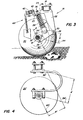
- the disc harrow 10 which is shown in Fig. 1, comprises a plurality of disc sets 12. Each is supported suspended by a frame member 14 of rectangular cross-section with the aid of at least two brackets 16. Each disc extension 12 comprises an elongated set bolt 18, on which a plurality of discs 20 designed as tillage tools are arranged at fixed mutual axial distances.
- each bracket 16 comprises a rigid support member 22, the upper end 23 of which is attached or screwed to the frame member 14.
- the upper end of the support member 22 includes a generally rearwardly projecting flange 24 with a bore 25.
- the support member 22 extends between the upper end 23 and the lower end 26 substantially downward and slightly forward or in the direction of travel.
- Each bracket 16 further includes a rigid support arm 28, the front end of which is articulated at the articulation point 30 on the lower end 26 of the support member 22.
- the articulation point 30 enables the bearing arm 28 to be pivoted in a vertical plane, but prevents the arm 28 from being able to pivot or tilt relative to the support member 22 in a horizontal plane.
- a bearing arrangement 32 is screwed tight.
- the horizontal distance between the articulation point 30 and the bearing arrangement 32 is greater than the vertical or perpendicular distance between these two points.
- a yoke element 34 is articulated to a central region of the bearing arm 28 between its front and rear ends.
- the shaft of a bolt 36 extends through the bore 25 of the flange 24. Its threaded end engages in the yoke part 34.
- the head of the bolt 36 lies against the top of the flange 24 and in this way limits the pivoting movement of the bearing arm 28 downwards.
- a predetermined preload or compression of a spring element 38 is maintained by this system.
- the spring element 38 is shown in the example shown as a coil spring.
- the coil spring 38 coaxially surrounds the shaft of the bolt 36.
- the spring is clamped in this way between the yoke 34 and the underside of the flange 24.
- the rear end of the flange 24 ends in a holder 40 to which a tubular cross member 42 can be screwed.
- a plurality of scraper blades 44 are pivotally mounted on the cross member 42 and are each held or biased into engagement with one of the disks 20 by springs 45.
- the discs 20 are typically pulled through the ground in one direction, as indicated by the arrow 50 in FIG. 2.
- the direction of travel is at a predetermined angle with respect to the vertical planes of the disks 20.
- the passage of the disks 20 through the soil typically generates labor or reaction forces which act on the disk set 12 in a direction which is relatively small in inclination has on the horizontal plane and the direction of travel of the disks 20 is opposite.
- These workers can act nonuniformly on the opposite ends of a set of disks 12, for example when one end of the set of disks engages deeper than the other end. These unequal workers tend to tilt or pivot the disc set 12 in a horizontal plane relative to the frame 14.
- the bearing arm extends essentially horizontally and backwards from the lower end 26 of the support member 22 when the disc harrow is in the normal working position. Due to this arrangement and due to the pivot connection at the articulation point 30 between the support member 22 and the bearing arm 28 it is achieved that the bearing arm 28 is prevented from pivoting or tilting in a horizontal plane in relation to the support member 22 and the frame member 14 by the bearing arm so on the support is guided member that it can only pivot about the horizontal axis of the articulation point 30.
- the set pin 18 is guided with the associated disks 20 so that this unit can essentially only move in a vertical direction while movement in a horizontal or lateral direction is largely excluded, for example under the influence of the above-mentioned unequal reaction forces.
- Two such holders 16, which are arranged at a mutual distance between the frame member 14 and the disk set 12, can thus reliably prevent the disk set 12 from tilting in a horizontal plane relative to the frame member 14. Rather, the two brackets can reliably maintain the desired angle between the planes of the disks 20 and the associated direction of travel.
- a typical reaction force during normal operation acts on the disks 20 in the direction of the arrow 54 (see FIG. 3). This force tends to pivot the bearing arm 28, the set pin 18 and the disks 20 upward and thus clockwise with respect to the frame member 14 and the support member 22 (based on the illustration in FIG. 3).
- the adjusting bolt 36 can be adjusted to adjust the bias of the spring 38 so that the bias or preload of the spring 38 is large enough to substantially preclude any pivoting movement of the bearing arm 28 and the washers 20 during normal operation.
- the holder is thus a rigid link as long as normal working conditions with normal reaction forces prevail due to the ground intervention.
- the reaction force from the obstacle has a substantially larger vertical component which is sufficient to overcome the bias of the springs 38 so that the bearing arm 28 with the disk 20 can pivot clockwise around the articulation point 30, whereby the disk 20 over the obstacle climbs away.
- the spring 38 can absorb and dissipate the impact energy between the disc 20 and the obstacle, so that damage to the components of the disc harrow 10 is reliably excluded.
- the typical working or reaction force 54 acts on the bearing arm 28 over a moment arm with the length A, which is shown in FIG. 3.
- the substantially steeper reaction force 60 of the obstacle acts on the bearing arm over a substantially longer moment arm B, which is also shown in FIG. 3.
- Figure 3 it can be seen that the moment arm through which some force acts on the bearing arm 28 decreases as the angle of the force decreases with respect to a horizontal plane.
- the disk 20 and the bearing arm 28 tilt about a pivot point 30 which is substantially below the plane of the frame member 14 and almost at the same vertical level as the axis of the set pin 18.
- the moment resulting from this force tends to urge the support arm 28 and one of the washers 20 upward during a collision between the washer and an obstacle, much greater than the moment of force that results from normal, typical operation.
- the bracket 16 according to the invention is essentially rigid during normal operation, but can yield in the desired manner when one of the disks hits an obstacle.
Landscapes
- Life Sciences & Earth Sciences (AREA)
- Engineering & Computer Science (AREA)
- Mechanical Engineering (AREA)
- Soil Sciences (AREA)
- Environmental Sciences (AREA)
- Soil Working Implements (AREA)
Claims (4)
Applications Claiming Priority (2)
| Application Number | Priority Date | Filing Date | Title |
|---|---|---|---|
| US172363 | 1980-07-25 | ||
| US06/172,363 US4333535A (en) | 1980-07-25 | 1980-07-25 | Disc standard assembly |
Publications (2)
| Publication Number | Publication Date |
|---|---|
| EP0045060A1 EP0045060A1 (fr) | 1982-02-03 |
| EP0045060B1 true EP0045060B1 (fr) | 1984-10-10 |
Family
ID=22627408
Family Applications (1)
| Application Number | Title | Priority Date | Filing Date |
|---|---|---|---|
| EP81105819A Expired EP0045060B1 (fr) | 1980-07-25 | 1981-07-23 | Fixation pour le support flexible d'une section à disques du cadre d'un pulvériseur à disques ou d'outils semblables |
Country Status (9)
| Country | Link |
|---|---|
| US (1) | US4333535A (fr) |
| EP (1) | EP0045060B1 (fr) |
| AR (1) | AR230916A1 (fr) |
| AU (1) | AU533922B2 (fr) |
| CA (1) | CA1154292A (fr) |
| DE (1) | DE3166604D1 (fr) |
| DK (1) | DK330481A (fr) |
| ES (1) | ES8204575A1 (fr) |
| ZA (1) | ZA814530B (fr) |
Cited By (2)
| Publication number | Priority date | Publication date | Assignee | Title |
|---|---|---|---|---|
| DE4137587A1 (de) * | 1990-11-15 | 1992-06-04 | Kverneland Klepp As | Pflugkoerperaufhaengung |
| DE10137624A1 (de) * | 2001-08-03 | 2003-05-15 | Fritz Guettler | Scheibenschar |
Families Citing this family (31)
| Publication number | Priority date | Publication date | Assignee | Title |
|---|---|---|---|---|
| US4396070A (en) * | 1981-07-09 | 1983-08-02 | Harley Brandner | Pivotal disc gang section |
| US4407372A (en) * | 1981-09-17 | 1983-10-04 | International Harvester Co. | Disk harrow with cushion gang |
| US4492272A (en) * | 1982-03-15 | 1985-01-08 | Deere & Company | Tillage implement and improved gang assembly therefor |
| GB2146881B (en) * | 1983-09-22 | 1986-10-08 | Dowdeswell C V R | Yieldable mounting of plough members |
| NZ211009A (en) * | 1984-06-12 | 1986-09-10 | I M Miller | Eccentric wheel mounting for wheelbarrow and similar applications |
| US4796550A (en) * | 1985-03-29 | 1989-01-10 | Deere & Co. | Single angled blade coulter and fertilizer opener |
| US4842077A (en) * | 1988-06-20 | 1989-06-27 | Deere & Company | Disk harrow standard for support beams of different cross sections |
| US4883126A (en) * | 1989-02-21 | 1989-11-28 | Gregory Leland | Ridge planter guide unit |
| US5042590A (en) * | 1990-09-20 | 1991-08-27 | Deere & Company | Tapered C-spring for a disk harrow |
| WO1993000791A1 (fr) * | 1991-07-02 | 1993-01-21 | Januschkowetz Gesellschaft M.B.H. | Semoir mobile |
| US5785129A (en) * | 1995-12-01 | 1998-07-28 | Keller; Russell J. | Row crop cultivator having a fixed depth of penetration |
| CA2250677A1 (fr) * | 1998-10-20 | 2000-04-20 | Dean Jay Mayerle | Fertilisant/ouvreur de feves de soya (fofs) |
| US6158523A (en) | 1998-10-30 | 2000-12-12 | Sunflower Manufacturing Co., Inc. | Agricultural disc mounting system and method |
| CA2273461C (fr) | 1999-06-02 | 2007-08-07 | Bourgault Industries Ltd. | Systeme de degagement rapide et de rangement base sur un element a rotation excentrique |
| US6223832B1 (en) * | 1999-06-03 | 2001-05-01 | Deere & Company | Constant pressure scraper system with adjustment |
| CA2375755C (fr) | 2001-03-06 | 2005-07-05 | Salford Farm Machinery Ltd. | Bras de palier de pivot a ressort |
| US7290620B2 (en) * | 2004-02-27 | 2007-11-06 | Cnh America Llc | Disk blade scrapers for tillage apparatus |
| US11252852B2 (en) | 2006-05-15 | 2022-02-22 | Pro Mags Llc | Gauge wheel and universal scraper for use with a conventional row planter assembly |
| US9769971B2 (en) * | 2006-05-15 | 2017-09-26 | Pro Mags Llc | Gauge wheel and universal scraper for use with a conventional row planter assembly |
| US8196671B2 (en) * | 2008-04-10 | 2012-06-12 | Deere & Company | Opener disk blade scraper hinge geometry to maintain contact with deflected disk blade |
| US7753134B1 (en) | 2009-07-31 | 2010-07-13 | Cnh America Llc | Coulter assembly |
| US8381827B2 (en) * | 2009-12-09 | 2013-02-26 | Salford Farm Machinery Ltd. | Spring mounted blade assembly and tillage implement therewith |
| DK177697B1 (en) | 2012-11-26 | 2014-03-17 | Dal Bo As | A device for stubble treatment |
| RU2568469C1 (ru) | 2013-08-21 | 2015-11-20 | СиЭнЭйч ИНДАСТРИАЛ АМЕРИКА ЭлЭлСи | Почвообрабатывающее орудие со стопором для упругой опоры |
| RU2014124720A (ru) * | 2013-08-21 | 2015-12-27 | СиЭнЭйч ИНДАСТРИАЛ АМЕРИКА ЭлЭлСи | Шпиндель дискового ножа |
| US20150129262A1 (en) * | 2013-11-13 | 2015-05-14 | Cnh Industrial America Llc | Tillage implement scraper assembly |
| WO2015103707A1 (fr) | 2014-01-09 | 2015-07-16 | Salford Group Inc. | Ensemble roue coutre à angle réglable |
| US9769974B2 (en) | 2014-06-24 | 2017-09-26 | Deere & Company | Combination C-shaped spring and system |
| AR102012A1 (es) * | 2014-10-30 | 2017-02-01 | A M A S P A | Unidad y método de labranza del terreno |
| US10287005B2 (en) * | 2015-03-13 | 2019-05-14 | Bell Helicopter Textron Inc. | Friction damper with centering flexure |
| EP3487279B1 (fr) | 2016-07-25 | 2022-10-05 | AGCO Corporation | Outil de travail du sol comprenant un mécanisme permettant de régler un angle de lame de disque |
Family Cites Families (23)
| Publication number | Priority date | Publication date | Assignee | Title |
|---|---|---|---|---|
| US2675659A (en) * | 1954-04-20 | Resilient biasing means ifor harrow | ||
| US1331722A (en) * | 1919-01-18 | 1920-02-24 | Burch Plow Works Co | Pulverizer |
| US1884273A (en) * | 1930-04-02 | 1932-10-25 | Ernest C Sandeen | Disk pulverizer |
| US2336848A (en) * | 1942-07-08 | 1943-12-14 | Joseph E Cruse | Hydraulic disk frame |
| US2762182A (en) * | 1952-07-05 | 1956-09-11 | Ferguson Harry Inc | Disc harrow |
| US2979138A (en) * | 1959-01-28 | 1961-04-11 | Int Harvester Co | Flexible disk tiller |
| US3061018A (en) * | 1960-04-26 | 1962-10-30 | Howard O Olson | Spring-loaded coulter disc |
| US3213947A (en) * | 1964-02-19 | 1965-10-26 | Int Harvester Co | Cushioned frame for agricultural implement |
| FR1417208A (fr) * | 1964-09-22 | 1965-11-12 | Gard Pere & Fils | Support élastique de disque pour pulvériseur à disques à usage agricole |
| US3493055A (en) * | 1966-04-25 | 1970-02-03 | Kewanee Mach & Conveyor Co | Cultivator shank structure |
| US3442336A (en) * | 1966-07-21 | 1969-05-06 | Int Harvester Co | Flexible mounting for disk harrow gang |
| US3454106A (en) * | 1966-09-26 | 1969-07-08 | Deere & Co | Disk harrow |
| US3620310A (en) * | 1969-07-22 | 1971-11-16 | Massey Ferguson Inc | Implement spring cushion |
| US3640348A (en) * | 1970-02-02 | 1972-02-08 | Kewanee Mach & Conveyor Co | S-shaped standard |
| US3700037A (en) * | 1971-01-25 | 1972-10-24 | Deere & Co | Plow colter with yieldable force-applying means and adjustable overload mount for colter carrying arm |
| US3700038A (en) * | 1971-03-03 | 1972-10-24 | Deere & Co | Adjustable spring trip shank assembly |
| US3700039A (en) * | 1971-03-03 | 1972-10-24 | Deere & Co | Spring trip shank assembly |
| US3757871A (en) * | 1972-01-26 | 1973-09-11 | Deere & Co | Minimum tillage agricultural implement |
| US3981367A (en) * | 1975-09-29 | 1976-09-21 | Allis-Chalmers Corporation | Spring trip cultivator shank assembly |
| US4066132A (en) * | 1976-02-20 | 1978-01-03 | Deere & Company | Disk harrow with beam member suspended by u-shaped springs |
| US4004640A (en) * | 1976-02-23 | 1977-01-25 | Bland Charles W | Hanger mechanism and sail engaging tool attached to tool bar thereby |
| US4193456A (en) * | 1978-04-17 | 1980-03-18 | Ankeman Dale E | Biased agricultural implement |
| US4213505A (en) * | 1978-08-14 | 1980-07-22 | Jolley Glenn L | Tractor implement carrying apparatus |
-
1980
- 1980-07-25 US US06/172,363 patent/US4333535A/en not_active Expired - Lifetime
-
1981
- 1981-04-29 AU AU69958/81A patent/AU533922B2/en not_active Ceased
- 1981-06-25 CA CA000380588A patent/CA1154292A/fr not_active Expired
- 1981-07-03 ZA ZA814530A patent/ZA814530B/xx unknown
- 1981-07-22 ES ES504187A patent/ES8204575A1/es not_active Expired
- 1981-07-23 AR AR286198A patent/AR230916A1/es active
- 1981-07-23 DE DE8181105819T patent/DE3166604D1/de not_active Expired
- 1981-07-23 EP EP81105819A patent/EP0045060B1/fr not_active Expired
- 1981-07-24 DK DK330481A patent/DK330481A/da not_active Application Discontinuation
Cited By (3)
| Publication number | Priority date | Publication date | Assignee | Title |
|---|---|---|---|---|
| DE4137587A1 (de) * | 1990-11-15 | 1992-06-04 | Kverneland Klepp As | Pflugkoerperaufhaengung |
| DE10137624A1 (de) * | 2001-08-03 | 2003-05-15 | Fritz Guettler | Scheibenschar |
| DE10137624B4 (de) * | 2001-08-03 | 2006-04-27 | Güttler, Fritz | Scheibenschar |
Also Published As
| Publication number | Publication date |
|---|---|
| AU533922B2 (en) | 1983-12-15 |
| AU6995881A (en) | 1982-01-21 |
| DE3166604D1 (en) | 1984-11-15 |
| ES504187A0 (es) | 1982-05-16 |
| US4333535A (en) | 1982-06-08 |
| ES8204575A1 (es) | 1982-05-16 |
| ZA814530B (en) | 1983-02-23 |
| DK330481A (da) | 1982-01-26 |
| CA1154292A (fr) | 1983-09-27 |
| AR230916A1 (es) | 1984-08-31 |
| EP0045060A1 (fr) | 1982-02-03 |
Similar Documents
| Publication | Publication Date | Title |
|---|---|---|
| EP0045060B1 (fr) | Fixation pour le support flexible d'une section à disques du cadre d'un pulvériseur à disques ou d'outils semblables | |
| DE19818960A1 (de) | Aufhängung eines Vorsatzes | |
| DE2532996A1 (de) | Ueberlastsicherung der verbindung zwischen bodenbearbeitungswerkzeugen und ihren tragrahmen | |
| DE2725233C2 (de) | Bodenbearbeitungsmaschine | |
| EP0081121A1 (fr) | Dent flexible | |
| EP0081742A1 (fr) | Appareil à travailler la terre déplaçable sur un champ | |
| EP1266551A2 (fr) | Appareil de travail pour le montage sur véhicule | |
| EP0394830B1 (fr) | Machine agricole, en particulier faucheuse, destinée à être montée sur un tracteur | |
| DE2632002C2 (de) | Mähmaschine | |
| DE2528928A1 (de) | Landwirtschaftliches bodenbearbeitungsgeraet, insbesondere kruemler | |
| DE7118201U (de) | Bodenbearbeitungsgeraet mit werkzeugausloesevorrichtung | |
| DE2807240A1 (de) | Drehpflug | |
| DE2633428A1 (de) | Anbauvorrichtung zum anbau von geraeten, insbesondere schneeraeumgeraeten | |
| DE4202771C2 (de) | Überlastsicherung von Bodenbearbeitungsmaschinen | |
| DE2532783A1 (de) | Maehvorrichtung | |
| DE3546445A1 (de) | Vorrichtung zum vorschnitt von rebholz an weinstoecken in drahtrahmenanlagen mit kordonerziehung | |
| EP0313835B1 (fr) | Plaque d'arrêt pour outil combiné comportant une fraise | |
| DE3106660C2 (de) | Bodenbearbeitungsgerät im wesentlichen in Art einer Scheibenegge oder dergleichen | |
| DE3546479C2 (fr) | ||
| EP0295510B1 (fr) | Rouleau de sol | |
| DE1582292B2 (de) | Mähmaschine | |
| DE2835505C2 (fr) | ||
| EP0118868A2 (fr) | Machine pour le travail du sol | |
| DE3325620C2 (de) | Schneepflug | |
| EP0182162B1 (fr) | Machine pour le travail du sol entraînée par un tracteur |
Legal Events
| Date | Code | Title | Description |
|---|---|---|---|
| PUAI | Public reference made under article 153(3) epc to a published international application that has entered the european phase |
Free format text: ORIGINAL CODE: 0009012 |
|
| AK | Designated contracting states |
Designated state(s): DE FR GB |
|
| 17P | Request for examination filed |
Effective date: 19820122 |
|
| EL | Fr: translation of claims filed | ||
| GRAA | (expected) grant |
Free format text: ORIGINAL CODE: 0009210 |
|
| AK | Designated contracting states |
Designated state(s): DE FR GB |
|
| REF | Corresponds to: |
Ref document number: 3166604 Country of ref document: DE Date of ref document: 19841115 |
|
| ET | Fr: translation filed | ||
| PLBE | No opposition filed within time limit |
Free format text: ORIGINAL CODE: 0009261 |
|
| STAA | Information on the status of an ep patent application or granted ep patent |
Free format text: STATUS: NO OPPOSITION FILED WITHIN TIME LIMIT |
|
| 26N | No opposition filed | ||
| PG25 | Lapsed in a contracting state [announced via postgrant information from national office to epo] |
Ref country code: FR Free format text: LAPSE BECAUSE OF NON-PAYMENT OF DUE FEES Effective date: 19880331 |
|
| PG25 | Lapsed in a contracting state [announced via postgrant information from national office to epo] |
Ref country code: DE Effective date: 19880401 |
|
| GBPC | Gb: european patent ceased through non-payment of renewal fee | ||
| REG | Reference to a national code |
Ref country code: FR Ref legal event code: ST |
|
| PG25 | Lapsed in a contracting state [announced via postgrant information from national office to epo] |
Ref country code: GB Free format text: LAPSE BECAUSE OF NON-PAYMENT OF DUE FEES Effective date: 19881118 |