EP0045060B1 - Holding device for the flexible mounting of a disk gang to the frame of a disk harrow or the like - Google Patents
Holding device for the flexible mounting of a disk gang to the frame of a disk harrow or the like Download PDFInfo
- Publication number
- EP0045060B1 EP0045060B1 EP81105819A EP81105819A EP0045060B1 EP 0045060 B1 EP0045060 B1 EP 0045060B1 EP 81105819 A EP81105819 A EP 81105819A EP 81105819 A EP81105819 A EP 81105819A EP 0045060 B1 EP0045060 B1 EP 0045060B1
- Authority
- EP
- European Patent Office
- Prior art keywords
- mounting
- frame
- support member
- mounting arm
- arm
- Prior art date
- Legal status (The legal status is an assumption and is not a legal conclusion. Google has not performed a legal analysis and makes no representation as to the accuracy of the status listed.)
- Expired
Links
Images

Classifications
-
- A—HUMAN NECESSITIES
- A01—AGRICULTURE; FORESTRY; ANIMAL HUSBANDRY; HUNTING; TRAPPING; FISHING
- A01B—SOIL WORKING IN AGRICULTURE OR FORESTRY; PARTS, DETAILS, OR ACCESSORIES OF AGRICULTURAL MACHINES OR IMPLEMENTS, IN GENERAL
- A01B21/00—Harrows with rotary non-driven tools
- A01B21/08—Harrows with rotary non-driven tools with disc-like tools
Definitions
- the invention relates to a holder for a resilient support of a set of discs on the frame of a disc harrow or the like on the bearing arm engaging elastic device, which is articulated with its lower end to a central region of the bearing arm between its front articulation end and its rear bearing for the set of discs, the front end of the bearing arm being attached to and from the lower end of a frame below projecting support member is articulated so that it can only perform pivoting movements about a horizontal axis and the elastic device opposes the upward movement of the bearing arm a predetermined elastic resistance.
- the rod has a compression spring which is threaded on the upper end of the rod and is supported on an abutment at the upper end.
- the fork connected to the pivot shaft is additionally connected to the bearing arm via a chain, so that the bearing arm can be raised when the pivot shaft is pivoted.
- all parts of the support rod forming the bracket protrude far beyond the circumference of the discs which form the disc set. The arrangement is therefore not only complicated, but also requires a lot of installation space and is easily exposed to damage due to the numerous parts and their great length.
- the upper end of the support member has a substantially rearward projecting flange, that the elastic device is supported with its upper end on this flange of the support member and that the effective length of the bearing arm between the articulation point and the storage end having no greater than the radius of the discs of the disc set.
- the support member serves at the same time to support the bearing arm and the elastic device.
- the elastic device is practically parallel and directly next to the support member.
- the installation space for the bracket is therefore extremely small, with no parts protruding above the harrow frame.
- Due to the compact structure, the arrangement is also extremely robust. It consists of only a few parts and is therefore easy to assemble. It has only a few storage positions and is therefore subject to only slight wear. Because of the short overall lengths of the individual parts, they can be designed to be particularly resilient without increasing their weight.
- the articulation point of the bearing arm on the support member comes to lie comparatively deep under the harrow frame, since the length of the support member is approximately the length of the elastic device tung corresponds.
- the reaction force acts on the bearing arm during normal operation with only a relatively small torque arm, so that a relatively low pretensioning force is sufficient to hold the bearing arm in a predetermined position during normal operation and to hold the disks of the disk set in the soil at a predetermined depth of penetration.
- the reaction force that occurs when hitting an obstacle is sufficient to reliably overcome the pretensioning force.
- the structure of the holder is extremely simple and easy and inexpensive to manufacture and has only a few places subject to wear.
- the compact structure also simplifies the assembly of a conventional scraping device to keep the individual disks of the disk set free.
- the disc harrow 10 which is shown in Fig. 1, comprises a plurality of disc sets 12. Each is supported suspended by a frame member 14 of rectangular cross-section with the aid of at least two brackets 16. Each disc extension 12 comprises an elongated set bolt 18, on which a plurality of discs 20 designed as tillage tools are arranged at fixed mutual axial distances.
- each bracket 16 comprises a rigid support member 22, the upper end 23 of which is attached or screwed to the frame member 14.
- the upper end of the support member 22 includes a generally rearwardly projecting flange 24 with a bore 25.
- the support member 22 extends between the upper end 23 and the lower end 26 substantially downward and slightly forward or in the direction of travel.
- Each bracket 16 further includes a rigid support arm 28, the front end of which is articulated at the articulation point 30 on the lower end 26 of the support member 22.
- the articulation point 30 enables the bearing arm 28 to be pivoted in a vertical plane, but prevents the arm 28 from being able to pivot or tilt relative to the support member 22 in a horizontal plane.
- a bearing arrangement 32 is screwed tight.
- the horizontal distance between the articulation point 30 and the bearing arrangement 32 is greater than the vertical or perpendicular distance between these two points.
- a yoke element 34 is articulated to a central region of the bearing arm 28 between its front and rear ends.
- the shaft of a bolt 36 extends through the bore 25 of the flange 24. Its threaded end engages in the yoke part 34.
- the head of the bolt 36 lies against the top of the flange 24 and in this way limits the pivoting movement of the bearing arm 28 downwards.
- a predetermined preload or compression of a spring element 38 is maintained by this system.
- the spring element 38 is shown in the example shown as a coil spring.
- the coil spring 38 coaxially surrounds the shaft of the bolt 36.
- the spring is clamped in this way between the yoke 34 and the underside of the flange 24.
- the rear end of the flange 24 ends in a holder 40 to which a tubular cross member 42 can be screwed.
- a plurality of scraper blades 44 are pivotally mounted on the cross member 42 and are each held or biased into engagement with one of the disks 20 by springs 45.
- the discs 20 are typically pulled through the ground in one direction, as indicated by the arrow 50 in FIG. 2.
- the direction of travel is at a predetermined angle with respect to the vertical planes of the disks 20.
- the passage of the disks 20 through the soil typically generates labor or reaction forces which act on the disk set 12 in a direction which is relatively small in inclination has on the horizontal plane and the direction of travel of the disks 20 is opposite.
- These workers can act nonuniformly on the opposite ends of a set of disks 12, for example when one end of the set of disks engages deeper than the other end. These unequal workers tend to tilt or pivot the disc set 12 in a horizontal plane relative to the frame 14.
- the bearing arm extends essentially horizontally and backwards from the lower end 26 of the support member 22 when the disc harrow is in the normal working position. Due to this arrangement and due to the pivot connection at the articulation point 30 between the support member 22 and the bearing arm 28 it is achieved that the bearing arm 28 is prevented from pivoting or tilting in a horizontal plane in relation to the support member 22 and the frame member 14 by the bearing arm so on the support is guided member that it can only pivot about the horizontal axis of the articulation point 30.
- the set pin 18 is guided with the associated disks 20 so that this unit can essentially only move in a vertical direction while movement in a horizontal or lateral direction is largely excluded, for example under the influence of the above-mentioned unequal reaction forces.
- Two such holders 16, which are arranged at a mutual distance between the frame member 14 and the disk set 12, can thus reliably prevent the disk set 12 from tilting in a horizontal plane relative to the frame member 14. Rather, the two brackets can reliably maintain the desired angle between the planes of the disks 20 and the associated direction of travel.
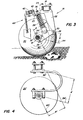
- a typical reaction force during normal operation acts on the disks 20 in the direction of the arrow 54 (see FIG. 3). This force tends to pivot the bearing arm 28, the set pin 18 and the disks 20 upward and thus clockwise with respect to the frame member 14 and the support member 22 (based on the illustration in FIG. 3).
- the adjusting bolt 36 can be adjusted to adjust the bias of the spring 38 so that the bias or preload of the spring 38 is large enough to substantially preclude any pivoting movement of the bearing arm 28 and the washers 20 during normal operation.
- the holder is thus a rigid link as long as normal working conditions with normal reaction forces prevail due to the ground intervention.
- the reaction force from the obstacle has a substantially larger vertical component which is sufficient to overcome the bias of the springs 38 so that the bearing arm 28 with the disk 20 can pivot clockwise around the articulation point 30, whereby the disk 20 over the obstacle climbs away.
- the spring 38 can absorb and dissipate the impact energy between the disc 20 and the obstacle, so that damage to the components of the disc harrow 10 is reliably excluded.
- the typical working or reaction force 54 acts on the bearing arm 28 over a moment arm with the length A, which is shown in FIG. 3.
- the substantially steeper reaction force 60 of the obstacle acts on the bearing arm over a substantially longer moment arm B, which is also shown in FIG. 3.
- Figure 3 it can be seen that the moment arm through which some force acts on the bearing arm 28 decreases as the angle of the force decreases with respect to a horizontal plane.
- the disk 20 and the bearing arm 28 tilt about a pivot point 30 which is substantially below the plane of the frame member 14 and almost at the same vertical level as the axis of the set pin 18.
- the moment resulting from this force tends to urge the support arm 28 and one of the washers 20 upward during a collision between the washer and an obstacle, much greater than the moment of force that results from normal, typical operation.
- the bracket 16 according to the invention is essentially rigid during normal operation, but can yield in the desired manner when one of the disks hits an obstacle.
Landscapes
- Life Sciences & Earth Sciences (AREA)
- Engineering & Computer Science (AREA)
- Mechanical Engineering (AREA)
- Soil Sciences (AREA)
- Environmental Sciences (AREA)
- Soil Working Implements (AREA)
Description
Die Erfindung betrifft eine Halterung für eine nachgiebige Abstützung eines Scheibensatzes an dem Rahmen einer Scheibenegge oder dgl. Gerät, mit einem mit dem Rahmen gelenkig verbundenen, sich im wesentlichen etwa horizontal erstreckenden Lagerarm, der an seinem rückwärtigen Ende den Scheibensatz drehbar unterstützt, und mit einer an dem Lagerarm angreifenden elastischen Einrichtung, die mit ihrem unteren Ende an einem mittleren Bereich des Lagerarmes zwischen dessen vorderem Anlenkende und dessen rückwärtiger Lagerung für den Scheibensatz angelenkt ist, wobei das vordere Ende des Lagerarmes an dem unteren Ende eines am Rahmen befestigten und von diesem nach unten ragenden Stützglied so angelenkt ist, daß er Schwenkbewegungen nur um eine horizontale Achse ausführen kann und die elastische Einrichtung der Aufwärtsbewegung des Lagerarmes einen vorbestimmten elastischen Widerstand entgegengesetzt.The invention relates to a holder for a resilient support of a set of discs on the frame of a disc harrow or the like on the bearing arm engaging elastic device, which is articulated with its lower end to a central region of the bearing arm between its front articulation end and its rear bearing for the set of discs, the front end of the bearing arm being attached to and from the lower end of a frame below projecting support member is articulated so that it can only perform pivoting movements about a horizontal axis and the elastic device opposes the upward movement of the bearing arm a predetermined elastic resistance.
Halterungen für die nachgiebige Abstützung eines Scheibensatzes sind in verschiedenen Ausführungsformen bekannt. So hat man in bestimmter Weise geformte Plattfedern vorgesehen, die in Seitenansicht C-förmig, S-förmig, Z-förmig oder nach Art einer Sicherheitsnadel gebogen und mit ihren Schenkelenden an dem Eggenrahmen bzw. an einem Lagerhalter des Scheibensatzes befestigt sein können (vgl. US-A-3 442 336, 3 640 348 oder 4 066 132).Mounts for the resilient support of a set of disks are known in various embodiments. Thus, in a certain way, shaped flat springs have been provided which, in side view, are C-shaped, S-shaped, Z-shaped or bent in the manner of a safety pin and can be attached with their leg ends to the harrow frame or to a bearing holder of the disk set (cf. US-A-3 442 336, 3 640 348 or 4 066 132).
Ferner sind relativ komplizierte Stützgestänge zwischen Eggenrahmen und dem Scheibensatz bekannt, deren Gestängeglieder eine oder mehrere Schraubenfedern als elastische Einrichtung zugeordnet sind. Solche komplizierten Gestängeanordnungen zeigen beispielsweise die US-A-2762182, 1884273 oder die US-A-2979138.Furthermore, relatively complicated support rods between the harrow frame and the disc set are known, the link members of which are assigned one or more coil springs as an elastic device. Such complicated linkage arrangements are shown, for example, in US-A-2762182, 1884273 or US-A-2979138.
Von der letzteren ist im Oberbegriff des Anspruchs 1 ausgegangen. Bei der bekannten Halterung ist ein am Rahmen befestigtes und von diesem nach unten ragendes Stützglied vorgesehen, an dessem unteren Ende das vordere Ende eines Lagerarms angelenkt ist, der an seinem etwa horizontal nach hinten weisenden rückwärtigen Ende die Lagerhalterung für den Scheibensatz trägt. Im Bereich der Mitte zwischen den Enden des Lagerarms greift eine elastische Einrichtung an, die eine nach oben ragende Stange aufweist, die etwa auf halber Länge an dem rückwärtigen freien Ende einer Gabel angelenkt ist, die ihrerseits sich nach vorn in Richtung auf das Rahmenglied erstreckt und an einer Schwenkwelle befestigt ist, die in einer an dem Rahmenglied befestigten Schwenklagerung drehbar gelagert ist. Oberhalb der Anlenkstelle an die Gabel weist die Stange eine Druckfeder auf, die auf dem oberen Ende der Stange aufgefädelt ist und sich am oberen Ende an einem Widerlager abstützt. Die mit der Schwenkwelle verbundene Gabel ist mit dem Lagerarm zusätzlich über eine Kette verbunden, so daß bei Verschwenken der Schwenkwelle der Lagerarm angehoben werden kann. Bei dieser bekannten Anordnung ragen alle Teile des die Halterung bildenden Stützgestänges weit über den Umfang der Scheiben hinaus, welche den Scheibensatz bilden. Die Anordnung ist daher nicht nur kompliziert, sondern benötigt auch sehr viel Einbauraum und ist wegen der zahlreichen Teile und ihrer großen Länge leicht Beschädigungen ausgesetzt.The latter is based on the preamble of claim 1. In the known holder is attached to the frame and projecting downward from this support member is provided, at the lower end of which the front end of a bearing arm is articulated, which carries the bearing holder for the set of discs at its rear end, which points approximately horizontally to the rear. In the region between the ends of the bearing arm, an elastic device engages, which has an upwardly projecting rod which is articulated approximately halfway along the rear free end of a fork, which in turn extends forward towards the frame member and is attached to a pivot shaft which is rotatably mounted in a pivot bearing attached to the frame member. Above the articulation point on the fork, the rod has a compression spring which is threaded on the upper end of the rod and is supported on an abutment at the upper end. The fork connected to the pivot shaft is additionally connected to the bearing arm via a chain, so that the bearing arm can be raised when the pivot shaft is pivoted. In this known arrangement, all parts of the support rod forming the bracket protrude far beyond the circumference of the discs which form the disc set. The arrangement is therefore not only complicated, but also requires a lot of installation space and is easily exposed to damage due to the numerous parts and their great length.
Wenn zur Abstützung von Scheibensätzen C-förmige Stützplattfedern verwendet werden, führen diese bei Auftreffen der Scheiben auf Hindernisse zu ungleichen Reaktionskräften und damit zu ungleicher Auslenkung. Dadurch verändert sich die relative Lage des Scheibensatzes gegenüber der Fahrtrichtung, was unerwünscht ist. Mit Halterungen, die durch Gestänge ausgebildet sind, kann erreicht werden, daß diese relative Lageänderung vermieden wird. Derartige, als Gestänge ausgebildete Halterungen, sind jedoch, wie aufgezeigt, kompliziert und nachteilig. Dies gilt nicht nur für Herstellung, sondern auch für Montage und Wartung.If C-shaped support springs are used to support sets of disks, these lead to unequal reaction forces and thus to unequal deflection when the disks hit obstacles. This changes the relative position of the set of disks with respect to the direction of travel, which is undesirable. With brackets which are formed by linkage, this relative change in position can be avoided. Such brackets designed as linkages are, as shown, complicated and disadvantageous. This applies not only to manufacture, but also to assembly and maintenance.
Es ist Aufgabe der Erfindung, eine Halterung der eingangs näher bezeichneten Art so weiterzubilden, daß die gewünschte Nachgiebigkeit ohne relative Veränderung der Lage gegenüber dem Eggenrahmen in einer horizontalen Ebene sichergestellt ist und zwar mit einer Halterung, die besonders einfach, robust, billig in Herstellung, Montage und Wartung und nur geringem Verschleiß unterworfen ist.It is an object of the invention to develop a holder of the type specified in the introduction in such a way that the desired flexibility is ensured in a horizontal plane without a relative change in the position relative to the harrow frame, specifically with a holder which is particularly simple, robust, inexpensive to manufacture, Assembly and maintenance and subject to little wear.
Diese Aufgabe wird erfindungsgemäß dadurch gelöst, daß das obere Ende des Stützgliedes einen im wesentlichen nach rückwärts ragenden Flansch aufweist, daß die elastische Einrichtung sich mit ihrem oberen Ende an diesem Flansch des Stützgliedes abstützt und daß die wirksame Länge des Lagerarmes zwischen Anlenkstelle und dem die Lagerung aufweisenden Ende nicht größer als der Radius der Scheiben des Scheibensatzes ist.This object is achieved in that the upper end of the support member has a substantially rearward projecting flange, that the elastic device is supported with its upper end on this flange of the support member and that the effective length of the bearing arm between the articulation point and the storage end having no greater than the radius of the discs of the disc set.
Bei dieser Ausführungsform dient das Stützglied gleichzeitig zur Abstützung des Lagerarmes und der elastischen Einrichtung. Dabei liegt die elastische Einrichtung praktisch parallel und unmittelbar neben dem Stützglied. Der Einbauraum für die Halterung ist damit außerordentlich klein, wobei keine Teile über den Eggenrahmen nach oben hinausragen. Durch den gedrängten Aufbau ist die Anordnung auch außerordentlich robust. Sie besteht nur aus wenigen Teilen und läßt sich daher leicht montieren. Sie hat nur wenige Lagerstellung und ist daher nur geringem Verschleiß unterworfen. Wegen der kurzen Baulängen der einzelnen Teile können diese ohne Gewichtsvermehrung besonders belastbar ausgebildet sein. Trotz der gedrängten Bauweise kommt der Anlenkpunkt des Lagerarms an dem Stützglied vergleichsweise tief unter dem Eggenrahmen zu liegen, da die Länge des Stützgliedes etwa der Länge der elastischen Einrichtung entspricht. Die Reaktionskraft greift bei normalem Betrieb mit nur relativ kleinem Drehmomentarm an dem Lagerarm an, so daß eine relativ geringe Vorspannkraft ausreicht, um den Lagerarm während des normalen Betriebes in einer vorbestimmten Stellung und die Scheiben des Scheibensatzes in einer vorbestimmten Eindringtiefe in das Erdreich zu halten. Auf der anderen Seite reicht die bei Auftreffen auf ein Hindernis auftretende Reaktionskraft aus, um die Vorspannkraft zuverlässig zu überwinden.In this embodiment, the support member serves at the same time to support the bearing arm and the elastic device. The elastic device is practically parallel and directly next to the support member. The installation space for the bracket is therefore extremely small, with no parts protruding above the harrow frame. Due to the compact structure, the arrangement is also extremely robust. It consists of only a few parts and is therefore easy to assemble. It has only a few storage positions and is therefore subject to only slight wear. Because of the short overall lengths of the individual parts, they can be designed to be particularly resilient without increasing their weight. Despite the compact design, the articulation point of the bearing arm on the support member comes to lie comparatively deep under the harrow frame, since the length of the support member is approximately the length of the elastic device tung corresponds. The reaction force acts on the bearing arm during normal operation with only a relatively small torque arm, so that a relatively low pretensioning force is sufficient to hold the bearing arm in a predetermined position during normal operation and to hold the disks of the disk set in the soil at a predetermined depth of penetration. On the other hand, the reaction force that occurs when hitting an obstacle is sufficient to reliably overcome the pretensioning force.
Die Halterung ist in ihrem Aufbau außerordentlich einfach und leicht und billig herzustellen und weist nur wenige, einem Verschleiß unterworfene Stellen auf. Der gedrängte Aufbau vereinfacht auch die Montage einer üblichen Schabeeinrichtung zum Freihalten der einzelnen Scheiben des Scheibensatzes.The structure of the holder is extremely simple and easy and inexpensive to manufacture and has only a few places subject to wear. The compact structure also simplifies the assembly of a conventional scraping device to keep the individual disks of the disk set free.
Die Erfindung wird nachfolgend anhand schematischer Zeichnungen an einem Ausführungsbeispiel näher erläutert: Es zeigt
- Fig. 1 eine perspektivische Ansicht einer Scheibenegge mit der Halterung gemäß der Erfindung.
- Fig. 2 in Draufsicht einen Scheibensatz, der an dem Eggenrahmen mit Hilfe der Halterung gemäß der Erfindung angebracht ist, wobei die Lage der einzelnen Scheiben gegenüber der Fahrtrichtung angedeutet ist.
- Fig. 3 eine Seitenansicht der neuen Halterung mit Blickrichtung entsprechend der Pfeile 3-3 in Fig. 2, und
- Fig. 4 in ähnlicher Darstellung wie Fig. 3 die Ausführung einer bisher häufig verwendeten Halterung.
- Fig. 1 is a perspective view of a disc harrow with the holder according to the invention.
- Fig. 2 in plan view a disc set which is attached to the harrow frame by means of the holder according to the invention, the position of the individual discs relative to the direction of travel is indicated.
- Fig. 3 is a side view of the new bracket looking in the direction of arrows 3-3 in Fig. 2, and
- Fig. 4 in a similar representation as Fig. 3, the execution of a previously used bracket.
Die Scheibenegge 10, die in Fig. 1 dargestellt ist, umfaßt mehrere Scheibensätze 12. Jeder ist von einem Rahmenglied 14 von rechteckförmigem Querschnitt mit Hilfe von wenigstens zwei Halterungen 16 hängend unterstützt. Jeder Scheibenansatz 12 umfaßt einen langgestreckten Satzbolzen 18, auf dem mehrere als Bodenbearbeitungswerkzeuge ausgebildete Scheiben 20 in festen gegenseitigen axialen Abständen angeordnet sind.The
Gemäß Fig. 2 und 3 umfaßt jede Halterung 16 ein starres Stützglied 22, dessen oberes Ende 23 an dem Rahmenglied 14 befestigt oder festgeschraubt ist. Das obere Ende des Stützgliedes 22 umfaßt einen im wesentlichen nach rückwärts ragenden Flansch 24 mit einer Bohrung 25. Das Stützglied 22 erstreckt sich zwischen dem oberen Ende 23 und dem unteren Ende 26 im wesentlichen nach unten und leicht nach vorne oder in Fahrtrichtung. Jede Halterung 16 umfaßt ferner einen starren Lagerarm 28, dessen vorderes Ende bei der Anlenkstelle 30 an dem unteren Ende 26 des Stützgliedes 22 angelenkt ist. Die Anlenkstelle 30 ermöglicht ein Schwenken des Lagerarmes 28 in einer senkrechten Ebene, verhindert jedoch, daß der Arm 28 gegenüber dem Stützglied 22 in einer horizontalen Ebene verschwenken oder verkippen kann. Am rückwärtigen Ende des Lagerarmes 28 ist eine Lageranordnung 32 festgeschraubt. Diese unterstützt drehbar den Satzbolzen 18, der sich durch die Lageranordnung erstreckt. Der horizontale Abstand zwischen der Anlenkstelle 30 und der Lageranordnung 32 ist größer als der senkrechte oder lotrechte Abstand zwischen diesen beiden Stellen. Ein Jochelement 34 ist an einem mittleren Bereich des Lagerarmes 28 zwischen dessen vorderem und rückwärtigem Ende angelenkt. Der Schaft eines Bolzens 36 erstreckt sich durch die Bohrung 25 des Flansches 24. Sein Gewindeende greift in den Jochteil 34 ein. Der Kopf des Bolzens 36 liegt an der Oberseite des Flansches 24 an und begrenzt auf diese Weise die Schwenkbewegung des Lagerarmes 28 nach unten. Gleichzeitig wird durch diese Anlage eine vorbestimmte Vorspannung oder Zusammenpressung eines Federelementes 38 aufrechterhalten. Das Federelement 38 ist im dargestellten Beispiel als Schraubenfeder gezeigt. Es ist jedoch ersichtlich, daß andere elastische Einrichtungen verwendet werden können. Die Schraubenfeder 38 umgibt koaxial den Schaft des Bolzens 36. Die Feder ist auf diese Weise zwischen dem Joch 34 und der Unterseite des Flansches 24 eingespannt. Das rückwärtige Ende des Flansches 24 endet in einer Halterung 40, an die ein rohrförmiges Querglied 42 angeschraubt sein kann. Mehrere Schaberklingen 44 sind an dem Querglied 42 schwenkbar gelagert und werden durch Federn 45 jeweils in Eingriff mit einer der Scheiben 20 gehalten oder vorgespannt.2 and 3, each
Bei Betrieb der Scheibenegge 10 werden die Scheiben 20 typischerweise in eine Richtung durch den Boden gezogen, wie sie in Fig. 2 durch den Pfeil 50 angedeutet ist. Dabei verläuft die Fahrtrichtung unter einem vorbestimmten Winkel in bezug auf die senkrechten Ebenen der Scheiben 20. Der Durchgang der Scheiben 20 durch das Erdreich erzeugt typischerweise Arbeits- oder Reaktionskräfte, welche auf den Scheibensatz 12 in einer Richtung einwirken, die eine relativ kleine Neigung in bezug auf die horizontale Ebene besitzt und der Fahrtrichtung der Scheiben 20 entgegengerichtet ist. Diese Arbeitskräfte können auf die entgegengesetzten Enden eines Scheibensatzes 12 ungleichförmig einwirken, beispielsweise dann, wenn das eine Ende des Scheibensatzes tiefer in das Erdreich eingreift als das andere Ende. Diese ungleichen Arbeitskräfte haben die Tendenz, den Scheibensatz 12 in einer horizontalen Ebene gegenüber dem Rahmen 14 zu kippen oder verschwenken.During operation of the
Mit Hilfe der neuen Halterung 16 erstreckt sich der Lagerarm im wesentlichen horizontal und gegenüber der Fahrtrichtung nach rückwärts vom unteren Ende 26 des Stützgliedes 22 aus, wenn sich die Scheibenegge in üblicher Arbeitsstellung befindet. Aufgrund dieser Anordnung und aufgrund der Schwenkverbindung am Anlenkpunkt 30 zwischen dem Stützglied 22 und dem Lagerarm 28 wird erreicht, daß der Lagerarm 28 gegenüber einem Verschwenken oder Kippen in einer horizontalen Ebene im Verhältnis zu dem Stützglied 22 und dem Rahmenglied 14 gehindert ist, indem der Lagerarm so an dem Stützglied geführt ist, daß er nur um die horizontale Achse der Anlenkstelle 30 schwenken kann. Damit wird der Satzbolzen 18 mit den zugehörigen Scheiben 20 so geführt, daß diese Einheit sich im wesentlichen nur in einer senkrechten Richtung bewegen kann während eine Bewegung in einer horizontalen oder seitlichen Richtung etwa unter dem Einfluß der oben erwähnten ungleichen Reaktionskräfte, weitgehend ausgeschlossen ist. Damit können zwei solche Halterungen 16, die im gegenseitigen Abstand zwischen dem Rahmenglied 14 und dem Scheibensatz 12 angeordnet sind, ein Kippen des Scheibensatzes 12 in einer horizontalen Ebene gegenüber dem Rahmenglied 14 zuverlässig verhindern. Die beiden Halterungen können vielmehr den gewünschten Winkel zwischen den Ebenen der Scheiben 20 und der zugehörigen Fahrtrichtung zuverlässig aufrechterhalten.With the help of the
Eine typische Reaktionskraft bei normalem Betrieb wirkt auf die Scheiben 20 in Richtung des Pfeiles 54 (vergl. Fig. 3). Diese Kraft neigt dazu, den Lagerarm 28, den Satzbolzen 18 und die Scheiben 20 nach oben und damit Uhrzeigersinne gegenüber dem Rahmenglied 14 und dem Stützglied 22 zu verschwenken (bezogen auf die Darstellung in Fig. 3). Der Einstellbolzen 36 kann jedoch zur Einstellung der Vorspannung der Feder 38 so verstellt werden, daß die Vorspannung oder Vorlast der Feder 38 ausreichend groß ist, um im wesentlichen jede Schwenkbewegung des Lagerarmes 28 und der Scheiben 20 während des normalen Betriebes auszuschließen. In diesem Falle und unter den genannten Umständen wird die Halterung somit als starres Glied, solange normale Arbeitsbedingungen bei normalen Reaktionskräften durch den Bodeneingriff vorherrschen.A typical reaction force during normal operation acts on the
Wenn jedoch eine der Scheiben 20 auf einen Felsen oder auf ein ähnliches Hindernis im Boden trifft kann diese Scheibe einem Widerstand ausgesetzt werden, dessen Reaktionskraft in bezug auf die horizontale Ebene eine wesentlich größere Neigung der Wirkrichtung als normalerweise aufweist, wie dies durch den Pfeil 60 in Fig. 3 angedeutet ist. Dadurch weist die Reaktionskraft von dem Hindernis eine wesentlich größere vertikale Komponente auf, die ausreicht, die Vorspannung der Federn 38 zu überwinden, so daß der Lagerarm 28 mit der Scheibe 20 um die Anlenkstelle 30 im Uhrzeigersinne schwenken kann, wodurch die Scheibe 20 über das Hindernis hinwegsteigt. Auf diese Weise kann die Feder 38 die Stoßenergie zwischen Scheibe 20 und dem Hindernis absorbieren und ableiten, so daß eine Beschädigung der Komponenten der Scheibenegge 10 zuverlässig ausgeschlossen ist.However, if one of the
Das Verständnis der Wirkungsweise der Halterung 16 kann durch eine Erörterung des auftretenden Momentenarmes noch erleichtert werden. Während des normalen Arbeitsbetriebes wirkt die typische Arbeits- oder Reaktionskraft 54 auf den Lagerarm 28 über einen Momentarm mit der Länge A, die in Fig. 3 aufgezeigt ist. Während des Auftreffens auf ein Hindernis wirkt die wesentlich steilere Reaktionskraft 60 des Hindernisses auf den Lagerarm über einen wesentlich längeren Momentenarm B, der ebenfalls in Fig. 3 eingezeichnet ist. Betrachtet man Fig. 3, so ist in der Tat ersichtlich, daß der Momentenarm, über den irgendeine Kraft auf den Lagerarm 28 einwirkt, abnimmt, wenn der Winkel der Kraft in bezug auf eine horizontale Ebene abnimmt.Understanding the operation of the
Vergleicht man demgegenüber eine bekannte Halterung gemäß Fig.4 mit C-förmiger Blattfeder, so wird deutlich, daß der Momentenarm A' über den die typischerweise relativ flach geneigte normale Reaktionskraft 54' auf die Halterung einwirkt, wesentlich größer ist als der Momentenarm B', mit dem die wesentlich steilere Reaktionskraft 60' bei Auftreffen einer Scheibe auf ein Hindernis zur Wirkung kommt. Dies ergibt sich aus der Tatsache, daß die Scheibe 20' um einen Anlenkpunkt 30' verschwenkt wird, der nahe dem oberen Ende der C-förmigen Blattfeder liegt.If, on the other hand, a known holder according to FIG. 4 is compared with a C-shaped leaf spring, it becomes clear that the moment arm A ', via which the typically relatively flat inclined normal reaction force 54' acts on the holder, is considerably larger than the moment arm B ', with which the substantially steeper reaction force 60 'comes into effect when a disk hits an obstacle. This results from the fact that the disc 20 'is pivoted about a pivot point 30' which is close to the upper end of the C-shaped leaf spring.
Im Gegensatz dazu kippen bei der neuen Halterung 60 die Scheibe 20 und der Lagerarm 28 um einen Schwenkpunkt 30, der wesentlich unterhalb der Ebene des Rahmengliedes 14 und nahezu auf dem gleichen senkrechten Niveau wie die Achse des Satzbolzens 18 liegt. Da außerdem die Reaktionskraft eines Hindernisses dazu neigt größer zu sein als die normale Arbeits-Reaktionskraft ist das sich aus dieser Kraft ergebende Moment, welches den Lagerarm 28 und eine der Scheiben 20 während einer Kollision zwischen der Scheibe und einem Hindernis nach oben zu drängen sucht, viel größer als das Kraftmoment, das sich bei normaler typischer Arbeitsweise ergibt. Damit ist die Halterung 16 gemäß der Erfindung während des normalen Arbeitsvorganges im wesentlichen starr, kann aber in der gewünschten Weise nachgeben, wenn eine der Scheiben auf ein Hindernis trifft.In contrast, in the
Claims (4)
Applications Claiming Priority (2)
| Application Number | Priority Date | Filing Date | Title |
|---|---|---|---|
| US06/172,363 US4333535A (en) | 1980-07-25 | 1980-07-25 | Disc standard assembly |
| US172363 | 2005-06-29 |
Publications (2)
| Publication Number | Publication Date |
|---|---|
| EP0045060A1 EP0045060A1 (en) | 1982-02-03 |
| EP0045060B1 true EP0045060B1 (en) | 1984-10-10 |
Family
ID=22627408
Family Applications (1)
| Application Number | Title | Priority Date | Filing Date |
|---|---|---|---|
| EP81105819A Expired EP0045060B1 (en) | 1980-07-25 | 1981-07-23 | Holding device for the flexible mounting of a disk gang to the frame of a disk harrow or the like |
Country Status (9)
| Country | Link |
|---|---|
| US (1) | US4333535A (en) |
| EP (1) | EP0045060B1 (en) |
| AR (1) | AR230916A1 (en) |
| AU (1) | AU533922B2 (en) |
| CA (1) | CA1154292A (en) |
| DE (1) | DE3166604D1 (en) |
| DK (1) | DK330481A (en) |
| ES (1) | ES504187A0 (en) |
| ZA (1) | ZA814530B (en) |
Cited By (2)
| Publication number | Priority date | Publication date | Assignee | Title |
|---|---|---|---|---|
| DE4137587A1 (en) * | 1990-11-15 | 1992-06-04 | Kverneland Klepp As | PLOW BODY SUSPENSION |
| DE10137624A1 (en) * | 2001-08-03 | 2003-05-15 | Fritz Guettler | Disk share, e.g. for stubble plowing or mulch seeding, has concave side and is mounted on spring shaped like question mark, share being attached to straight section and curved section being attached to frame |
Families Citing this family (31)
| Publication number | Priority date | Publication date | Assignee | Title |
|---|---|---|---|---|
| US4396070A (en) * | 1981-07-09 | 1983-08-02 | Harley Brandner | Pivotal disc gang section |
| US4407372A (en) * | 1981-09-17 | 1983-10-04 | International Harvester Co. | Disk harrow with cushion gang |
| US4492272A (en) * | 1982-03-15 | 1985-01-08 | Deere & Company | Tillage implement and improved gang assembly therefor |
| GB2146881B (en) * | 1983-09-22 | 1986-10-08 | Dowdeswell C V R | Yieldable mounting of plough members |
| NZ211009A (en) * | 1984-06-12 | 1986-09-10 | I M Miller | Eccentric wheel mounting for wheelbarrow and similar applications |
| US4796550A (en) * | 1985-03-29 | 1989-01-10 | Deere & Co. | Single angled blade coulter and fertilizer opener |
| US4842077A (en) * | 1988-06-20 | 1989-06-27 | Deere & Company | Disk harrow standard for support beams of different cross sections |
| US4883126A (en) * | 1989-02-21 | 1989-11-28 | Gregory Leland | Ridge planter guide unit |
| US5042590A (en) * | 1990-09-20 | 1991-08-27 | Deere & Company | Tapered C-spring for a disk harrow |
| WO1993000791A1 (en) * | 1991-07-02 | 1993-01-21 | Januschkowetz Gesellschaft M.B.H. | Transportable sowing machine |
| US5785129A (en) * | 1995-12-01 | 1998-07-28 | Keller; Russell J. | Row crop cultivator having a fixed depth of penetration |
| CA2250677A1 (en) * | 1998-10-20 | 2000-04-20 | Dean Jay Mayerle | Fertilizer/soybean opener (fso) |
| US6158523A (en) * | 1998-10-30 | 2000-12-12 | Sunflower Manufacturing Co., Inc. | Agricultural disc mounting system and method |
| CA2273461C (en) | 1999-06-02 | 2007-08-07 | Bourgault Industries Ltd. | Quick release and storage system based on an eccentric rotating element |
| US6223832B1 (en) * | 1999-06-03 | 2001-05-01 | Deere & Company | Constant pressure scraper system with adjustment |
| US6695069B2 (en) | 2001-03-06 | 2004-02-24 | Salford Farm Machinery Ltd. | Spring rockflex bearing arm |
| US7290620B2 (en) * | 2004-02-27 | 2007-11-06 | Cnh America Llc | Disk blade scrapers for tillage apparatus |
| US9769971B2 (en) * | 2006-05-15 | 2017-09-26 | Pro Mags Llc | Gauge wheel and universal scraper for use with a conventional row planter assembly |
| US11252852B2 (en) | 2006-05-15 | 2022-02-22 | Pro Mags Llc | Gauge wheel and universal scraper for use with a conventional row planter assembly |
| US8196671B2 (en) * | 2008-04-10 | 2012-06-12 | Deere & Company | Opener disk blade scraper hinge geometry to maintain contact with deflected disk blade |
| US7753134B1 (en) | 2009-07-31 | 2010-07-13 | Cnh America Llc | Coulter assembly |
| US8365837B2 (en) * | 2009-12-09 | 2013-02-05 | Salford Farm Machinery Ltd. | Resiliently mounted agricultural tool and implement therewith |
| DK177697B1 (en) | 2012-11-26 | 2014-03-17 | Dal Bo As | A device for stubble treatment |
| RU2014124720A (en) * | 2013-08-21 | 2015-12-27 | СиЭнЭйч ИНДАСТРИАЛ АМЕРИКА ЭлЭлСи | DISK KNIFE SPINDLE |
| RU2568469C1 (en) | 2013-08-21 | 2015-11-20 | СиЭнЭйч ИНДАСТРИАЛ АМЕРИКА ЭлЭлСи | Tillage tool with stopper for elastic support |
| US20150129262A1 (en) * | 2013-11-13 | 2015-05-14 | Cnh Industrial America Llc | Tillage implement scraper assembly |
| CA2935584C (en) | 2014-01-09 | 2022-02-01 | Salford Group Inc. | Angle adjustable coulter wheel assembly |
| US9769974B2 (en) | 2014-06-24 | 2017-09-26 | Deere & Company | Combination C-shaped spring and system |
| AR102012A1 (en) * | 2014-10-30 | 2017-02-01 | A M A S P A | UNIT AND METHOD OF LABRANZA DEL TERRENO |
| US10287005B2 (en) * | 2015-03-13 | 2019-05-14 | Bell Helicopter Textron Inc. | Friction damper with centering flexure |
| CA3030353A1 (en) | 2016-07-25 | 2018-02-01 | Agco Corporation | Tillage implement having a mechanism for adjusting disc blade angle |
Family Cites Families (23)
| Publication number | Priority date | Publication date | Assignee | Title |
|---|---|---|---|---|
| US2675659A (en) * | 1954-04-20 | Resilient biasing means ifor harrow | ||
| US1331722A (en) * | 1919-01-18 | 1920-02-24 | Burch Plow Works Co | Pulverizer |
| US1884273A (en) * | 1930-04-02 | 1932-10-25 | Ernest C Sandeen | Disk pulverizer |
| US2336848A (en) * | 1942-07-08 | 1943-12-14 | Joseph E Cruse | Hydraulic disk frame |
| US2762182A (en) * | 1952-07-05 | 1956-09-11 | Ferguson Harry Inc | Disc harrow |
| US2979138A (en) * | 1959-01-28 | 1961-04-11 | Int Harvester Co | Flexible disk tiller |
| US3061018A (en) * | 1960-04-26 | 1962-10-30 | Howard O Olson | Spring-loaded coulter disc |
| US3213947A (en) * | 1964-02-19 | 1965-10-26 | Int Harvester Co | Cushioned frame for agricultural implement |
| FR1417208A (en) * | 1964-09-22 | 1965-11-12 | Gard Pere & Fils | Elastic disc support for agricultural disc harrows |
| US3493055A (en) * | 1966-04-25 | 1970-02-03 | Kewanee Mach & Conveyor Co | Cultivator shank structure |
| US3442336A (en) * | 1966-07-21 | 1969-05-06 | Int Harvester Co | Flexible mounting for disk harrow gang |
| US3454106A (en) * | 1966-09-26 | 1969-07-08 | Deere & Co | Disk harrow |
| US3620310A (en) * | 1969-07-22 | 1971-11-16 | Massey Ferguson Inc | Implement spring cushion |
| US3640348A (en) * | 1970-02-02 | 1972-02-08 | Kewanee Mach & Conveyor Co | S-shaped standard |
| US3700037A (en) * | 1971-01-25 | 1972-10-24 | Deere & Co | Plow colter with yieldable force-applying means and adjustable overload mount for colter carrying arm |
| US3700038A (en) * | 1971-03-03 | 1972-10-24 | Deere & Co | Adjustable spring trip shank assembly |
| US3700039A (en) * | 1971-03-03 | 1972-10-24 | Deere & Co | Spring trip shank assembly |
| US3757871A (en) * | 1972-01-26 | 1973-09-11 | Deere & Co | Minimum tillage agricultural implement |
| US3981367A (en) * | 1975-09-29 | 1976-09-21 | Allis-Chalmers Corporation | Spring trip cultivator shank assembly |
| US4066132A (en) * | 1976-02-20 | 1978-01-03 | Deere & Company | Disk harrow with beam member suspended by u-shaped springs |
| US4004640A (en) * | 1976-02-23 | 1977-01-25 | Bland Charles W | Hanger mechanism and sail engaging tool attached to tool bar thereby |
| US4193456A (en) * | 1978-04-17 | 1980-03-18 | Ankeman Dale E | Biased agricultural implement |
| US4213505A (en) * | 1978-08-14 | 1980-07-22 | Jolley Glenn L | Tractor implement carrying apparatus |
-
1980
- 1980-07-25 US US06/172,363 patent/US4333535A/en not_active Expired - Lifetime
-
1981
- 1981-04-29 AU AU69958/81A patent/AU533922B2/en not_active Ceased
- 1981-06-25 CA CA000380588A patent/CA1154292A/en not_active Expired
- 1981-07-03 ZA ZA814530A patent/ZA814530B/en unknown
- 1981-07-22 ES ES504187A patent/ES504187A0/en active Granted
- 1981-07-23 DE DE8181105819T patent/DE3166604D1/en not_active Expired
- 1981-07-23 AR AR286198A patent/AR230916A1/en active
- 1981-07-23 EP EP81105819A patent/EP0045060B1/en not_active Expired
- 1981-07-24 DK DK330481A patent/DK330481A/en not_active Application Discontinuation
Cited By (3)
| Publication number | Priority date | Publication date | Assignee | Title |
|---|---|---|---|---|
| DE4137587A1 (en) * | 1990-11-15 | 1992-06-04 | Kverneland Klepp As | PLOW BODY SUSPENSION |
| DE10137624A1 (en) * | 2001-08-03 | 2003-05-15 | Fritz Guettler | Disk share, e.g. for stubble plowing or mulch seeding, has concave side and is mounted on spring shaped like question mark, share being attached to straight section and curved section being attached to frame |
| DE10137624B4 (en) * | 2001-08-03 | 2006-04-27 | Güttler, Fritz | disc Plow |
Also Published As
| Publication number | Publication date |
|---|---|
| US4333535A (en) | 1982-06-08 |
| AR230916A1 (en) | 1984-08-31 |
| AU6995881A (en) | 1982-01-21 |
| AU533922B2 (en) | 1983-12-15 |
| ES8204575A1 (en) | 1982-05-16 |
| EP0045060A1 (en) | 1982-02-03 |
| ZA814530B (en) | 1983-02-23 |
| DK330481A (en) | 1982-01-26 |
| ES504187A0 (en) | 1982-05-16 |
| DE3166604D1 (en) | 1984-11-15 |
| CA1154292A (en) | 1983-09-27 |
Similar Documents
| Publication | Publication Date | Title |
|---|---|---|
| EP0045060B1 (en) | Holding device for the flexible mounting of a disk gang to the frame of a disk harrow or the like | |
| DE2226449A1 (en) | PLOW TREE | |
| DE19818960A1 (en) | Wheel suspension for agricultural machine | |
| DE2532996A1 (en) | OVERLOAD PROTECTION OF THE CONNECTION BETWEEN SOIL WORKING TOOLS AND THEIR SUPPORTING FRAME | |
| DE3011212A1 (en) | HAY ADVERTISING MACHINE | |
| DE2725233C2 (en) | Tillage machine | |
| EP0081121A1 (en) | Spring tine | |
| EP0081742A1 (en) | Soil-working implement movable across a field | |
| EP1266551A2 (en) | Working machine for mounting on a vehicle | |
| EP0394830B1 (en) | Tractormounted agricultural tool, particularly circular mower | |
| DE2632002C2 (en) | mower | |
| DE2528928A1 (en) | AGRICULTURAL TILLAGE EQUIPMENT, IN PARTICULAR CROWDERS | |
| DE7118201U (en) | SOIL TILLING EQUIPMENT WITH TOOL RELEASE DEVICE | |
| DE2807240A1 (en) | ROTATING PLOW | |
| DE2633428A1 (en) | ATTACHMENT DEVICE FOR THE ATTACHMENT OF DEVICES, IN PARTICULAR SNOW ROOM DEVICES | |
| DE4202771C2 (en) | Overload protection of tillage machines | |
| DE2532783A1 (en) | MOWING DEVICE | |
| EP0313835B1 (en) | Stop plate for a combined apparatus comprising a rotary cultivator | |
| DE3546479C2 (en) | ||
| EP0295510B1 (en) | Landroller | |
| DE3106660C2 (en) | Soil cultivation device essentially in the form of a disc harrow or the like | |
| DE940380C (en) | Turning mechanism for tractor-drawn turning plows works automatically when the plow is lifted out | |
| DE1582292B2 (en) | mower | |
| DE2835505C2 (en) | ||
| EP0118868A2 (en) | Soil-working implement |
Legal Events
| Date | Code | Title | Description |
|---|---|---|---|
| PUAI | Public reference made under article 153(3) epc to a published international application that has entered the european phase |
Free format text: ORIGINAL CODE: 0009012 |
|
| AK | Designated contracting states |
Designated state(s): DE FR GB |
|
| 17P | Request for examination filed |
Effective date: 19820122 |
|
| EL | Fr: translation of claims filed | ||
| GRAA | (expected) grant |
Free format text: ORIGINAL CODE: 0009210 |
|
| AK | Designated contracting states |
Designated state(s): DE FR GB |
|
| REF | Corresponds to: |
Ref document number: 3166604 Country of ref document: DE Date of ref document: 19841115 |
|
| ET | Fr: translation filed | ||
| PLBE | No opposition filed within time limit |
Free format text: ORIGINAL CODE: 0009261 |
|
| STAA | Information on the status of an ep patent application or granted ep patent |
Free format text: STATUS: NO OPPOSITION FILED WITHIN TIME LIMIT |
|
| 26N | No opposition filed | ||
| PG25 | Lapsed in a contracting state [announced via postgrant information from national office to epo] |
Ref country code: FR Free format text: LAPSE BECAUSE OF NON-PAYMENT OF DUE FEES Effective date: 19880331 |
|
| PG25 | Lapsed in a contracting state [announced via postgrant information from national office to epo] |
Ref country code: DE Effective date: 19880401 |
|
| GBPC | Gb: european patent ceased through non-payment of renewal fee | ||
| REG | Reference to a national code |
Ref country code: FR Ref legal event code: ST |
|
| PG25 | Lapsed in a contracting state [announced via postgrant information from national office to epo] |
Ref country code: GB Free format text: LAPSE BECAUSE OF NON-PAYMENT OF DUE FEES Effective date: 19881118 |