EP0394830B1 - Tractormounted agricultural tool, particularly circular mower - Google Patents
Tractormounted agricultural tool, particularly circular mower Download PDFInfo
- Publication number
- EP0394830B1 EP0394830B1 EP90107396A EP90107396A EP0394830B1 EP 0394830 B1 EP0394830 B1 EP 0394830B1 EP 90107396 A EP90107396 A EP 90107396A EP 90107396 A EP90107396 A EP 90107396A EP 0394830 B1 EP0394830 B1 EP 0394830B1
- Authority
- EP
- European Patent Office
- Prior art keywords
- attachment according
- machine frame
- frame structure
- arms
- agricultural attachment
- Prior art date
- Legal status (The legal status is an assumption and is not a legal conclusion. Google has not performed a legal analysis and makes no representation as to the accuracy of the status listed.)
- Expired - Lifetime
Links
Images


Classifications
-
- A—HUMAN NECESSITIES
- A01—AGRICULTURE; FORESTRY; ANIMAL HUSBANDRY; HUNTING; TRAPPING; FISHING
- A01B—SOIL WORKING IN AGRICULTURE OR FORESTRY; PARTS, DETAILS, OR ACCESSORIES OF AGRICULTURAL MACHINES OR IMPLEMENTS, IN GENERAL
- A01B61/00—Devices for, or parts of, agricultural machines or implements for preventing overstrain
- A01B61/04—Devices for, or parts of, agricultural machines or implements for preventing overstrain of the connection between tools and carrier beam or frame
- A01B61/044—Devices for, or parts of, agricultural machines or implements for preventing overstrain of the connection between tools and carrier beam or frame the connection enabling a yielding pivoting movement around a substantially horizontal and transverse axis
- A01B61/046—Devices for, or parts of, agricultural machines or implements for preventing overstrain of the connection between tools and carrier beam or frame the connection enabling a yielding pivoting movement around a substantially horizontal and transverse axis the device including an energy accumulator for restoring the tool to its working position
-
- A—HUMAN NECESSITIES
- A01—AGRICULTURE; FORESTRY; ANIMAL HUSBANDRY; HUNTING; TRAPPING; FISHING
- A01B—SOIL WORKING IN AGRICULTURE OR FORESTRY; PARTS, DETAILS, OR ACCESSORIES OF AGRICULTURAL MACHINES OR IMPLEMENTS, IN GENERAL
- A01B59/00—Devices specially adapted for connection between animals or tractors and agricultural machines or implements
- A01B59/06—Devices specially adapted for connection between animals or tractors and agricultural machines or implements for machines mounted on tractors
- A01B59/064—Devices specially adapted for connection between animals or tractors and agricultural machines or implements for machines mounted on tractors for connection to the front of the tractor
Definitions
- the invention relates to an agricultural implement for front three-point attachment to a tractor according to the preamble of claim 1.
- the object of the present invention is to improve a generic machine so that it no longer has the defects inherent in it.
- This goal is achieved in that, in an embodiment according to the generic term, the arms on the support frame are directed so far down that the articulated connection at a distance below the machine frame immediately above that in Working tools close to the ground. Now that the distance from the support of the mowing drums on the ground to the transverse axis is small, the torque around the transverse axis remains so small even with relatively large starting forces on obstacles on the ground that the mower rotor tilts around the transverse axis and the associated operation Risk of damage to the mower rotors is avoided.
- a three-point linkage with an upper link (2) and lower links (3) is mounted at the top and bottom link points (4, 5) on the front of a tractor (1).
- Tension springs (6) act so that the three-point linkage is relieved.
- a support frame (7) belonging to a rotary mower is attached to the upper and lower links (2, 3).
- Firmly connected to the support frame (7) are two arms (8) (FIGS. 1 and 2) which point forwards and downwards from the support frame (7).
- a number of mowing drums (10) are mounted on a machine frame (9) and carry a casing (11), an annular collar (12) with knives (13) and a sliding plate (14).
- tension springs (15), elongated hole plates (16) and damping cylinders (17) establish a connection between the machine frame (9) and the support frame (7).
- support arms (18) are attached to the outer end faces of the machine frame (9). With their lower end, tabs (19) are connected in an articulated manner, which in turn are connected in an articulated manner at a pivot point (20) to the free ends of the arms (8).
- the tabs (19) are limited in their movement up and down by stops, not shown.
- the arms (27) receive a sleeve (28) at the lower end, which is penetrated by a transverse axis (29).
- Booms (31) are attached to the machine frame (9) and pass between the arms (21) to the rear. They carry stop bolts (32) which can interact with the back of the arms (21) and the stop cams (23) when reversing.
- Figures 5 and 6 show an embodiment which is similar to that of Figures 3 and 4.
- the arms (33) have angular slits at the lower end with a horizontal section (34) and a section (35) which rises backwards.
- the rollers (30) are at the front end of the slot (22).
- the stop bolts (32) then rest on the back of the arms (21) and on the stop cam (23).
- the mower is held in place and cannot impale itself in the ground. If the mower encounters an off-center obstacle while driving forward, a moment arises that turns the relevant side of the mower backwards. Because of the inclined position of the pendulum axis (25), the side of the mower that rotates backwards lifts up and can thus overcome the obstacle.
- the springs (6) are tensioned such that the rollers (30) lie in the kink of the angular slots (34, 35). For forward and backward travel, the same applies as described above. If the mower encounters an off-center obstacle, the roller (30) can rise on the corresponding side in the slot (35), as a result of which the mower side in question can move backwards and upwards. The effect is equivalent to that in the previously described versions.
Abstract
Description
Die Erfindung bezieht sich auf ein landwirtschaftliches Anbaugerät zum Front-Dreipunkt-Anbau an einem Schlepper nach dem Gattungsbegriff des Anspruches 1.The invention relates to an agricultural implement for front three-point attachment to a tractor according to the preamble of
Eine bekanntgewordene Ausführung eines solchen Gerätes ist zum Beispiel in der DE-U 87 01 093 dargestellt. Beim Vorschlag nach dieser Schrift ist das die Mähwerkzeuge tragende Maschinengestell um eine mit Abstand oberhalb des Maschinengestells liegende Querachse am Tragrahmen schwenkbar gelagert, so daß bei der Arbeit die Mähkreisel den Bodenkonturen folgen können. Nachteilig ist, daß der Höhenabstand von der Abstützung der Mähtrommeln am Boden bis zu der Querachse sehr groß ist. Dadurch ergibt sich bei Anlaufen der Mähtrommeln an Hindernissen am Boden durch die Anlaufkraft ein Drehmoment um die Querachse, das schon bei verhältnismäßig geringen Anlaufkräften zur Folge hat, daß die Mähtrommeln um die Querachse kippen und so mit dem Außenumfang ihrer die Mähmesser tragenden Ringkragen in den Boden einspießen. Beschädigungen der Mähtrommeln können die Folge sein.A known version of such a device is shown for example in DE-U 87 01 093. In the proposal according to this document, the machine frame carrying the mowing tools is pivotally mounted on the supporting frame about a transverse axis lying at a distance above the machine frame, so that the mowing rotors can follow the ground contours at work. It is disadvantageous that the height distance from the support of the mowing drums on the ground to the transverse axis is very large. This results in a torque around the transverse axis when the mowing drums start up against obstacles on the ground due to the starting force, which, even with relatively low starting forces, results in the mowing drums tipping over the transverse axis and thus with the outer circumference of their ring collars carrying the mowing blades into the ground impale. Damage to the mowing drums can result.
Aufgabe der vorliegenden Erfindung ist es, eine gattungsgemäße Maschine so zu verbessern, daß sie die ihr anhaftenden Mängel nicht mehr aufweist. Dieses Ziel wird dadurch erreicht, daß bei einer Ausführung nach dem Gattungsbegriff die Arme am Tragrahmen so weit nach unten gerichtet sind, daß die Gelenkverbindung mit Abstand unterhalb des Maschinengestelles unmittelbar oberhalb der in Bodennähe arbeitenden Arbeitswerkzeuge liegt. Da nun der Abstand von der Abstützung der Mähtrommeln am Boden bis zu der Querachse klein ist, bleibt auch bei verhältnismäßig großen Anlaufkräften an Hindernisse am Boden das Drehmoment um die Querachse immer noch so klein, daß ein Kippen der Mähkreisel um die Querachse und das damit verbundene Risiko einer Beschädigung der Mähkreisel vermieden wird.The object of the present invention is to improve a generic machine so that it no longer has the defects inherent in it. This goal is achieved in that, in an embodiment according to the generic term, the arms on the support frame are directed so far down that the articulated connection at a distance below the machine frame immediately above that in Working tools close to the ground. Now that the distance from the support of the mowing drums on the ground to the transverse axis is small, the torque around the transverse axis remains so small even with relatively large starting forces on obstacles on the ground that the mower rotor tilts around the transverse axis and the associated operation Risk of damage to the mower rotors is avoided.
Weitere Merkmale der Erfindung ergeben sich aus den Unteransprüchen, sowie aus der nachfolgenden Beschreibung.Further features of the invention emerge from the subclaims and from the following description.
Die Erfindung wird anhand von sechs Abbildungen am Beispiel eines Kreiselmähwerkes im Frontanbau erläutert.
Figur 1 zeigt ein Kreiselmähwerk in Arbeitsstellung in SeitenansichtFigur 2 zeigt den gleichen Gegenstand von vorneFigur 3 zeigt eine andere Ausführung in SeitenansichtFigur 4 zeigt den gleichen Gegenstand von vorneFigur 5 zeigt eine weitere Ausführung in Seitenansicht- Figur 6 zeigt den gleichen Gegenstand von vorne
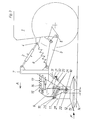
- Figure 1 shows a rotary mower in the working position in side view
- Figure 2 shows the same object from the front
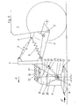
- Figure 3 shows another embodiment in side view
- Figure 4 shows the same object from the front
- Figure 5 shows another embodiment in side view
- Figure 6 shows the same object from the front
An der Stirnseite eines Schleppers (1) ist ein Dreipunktgestänge mit einem Oberlenker (2) und Unterlenkern (3) an oberen und unteren Anlenkpunkten (4, 5) montiert. Zugfedern (6) wirken so, daß das Dreipunkt-Gestänge entlastet wird. An den Ober- und Unterlenkern (2, 3) wird ein einem Kreiselmähwerk zugehöriger Tragrahmen (7) angebaut. Fest mit dem Tragrahmen (7) verbunden sind zwei Arme (8) (Figuren 1 und 2), die vom Tragrahmen (7) aus nach vorne und unten weisen.A three-point linkage with an upper link (2) and lower links (3) is mounted at the top and bottom link points (4, 5) on the front of a tractor (1). Tension springs (6) act so that the three-point linkage is relieved. A support frame (7) belonging to a rotary mower is attached to the upper and lower links (2, 3). Firmly connected to the support frame (7) are two arms (8) (FIGS. 1 and 2) which point forwards and downwards from the support frame (7).
An einem Maschinengestell (9) sind mehrere Mähtrommeln (10) gelagert, die einen Mantel (11), einen Ringkragen (12) mit Messern (13) und einen Gleitteller (14) tragen. Oberhalb des Maschinengestells (9) stellen Zugfedern (15), Langlochlaschen (16) und Dämpfungszylinder (17) eine Verbindung zwischen Maschinengestell (9) und Tragrahmen (7) her.A number of mowing drums (10) are mounted on a machine frame (9) and carry a casing (11), an annular collar (12) with knives (13) and a sliding plate (14). Above the machine frame (9), tension springs (15), elongated hole plates (16) and damping cylinders (17) establish a connection between the machine frame (9) and the support frame (7).
Bei der Ausführung nach Figuren 1 und 2 sind an den äußeren Stirnflächen des Maschinengestells (9) Stützarme (18) befestigt. Mit deren unterem Ende sind Laschen (19) gelenkig verbunden, die ihrerseits wieder in einem Drehpunkt (20) gelenkig an die freien Enden der Arme (8) angeschlossen sind. Die Laschen (19) sind durch nicht dargestellte Anschläge in ihrer Bewegung nach oben und unten begrenzt.In the embodiment according to FIGS. 1 and 2, support arms (18) are attached to the outer end faces of the machine frame (9). With their lower end, tabs (19) are connected in an articulated manner, which in turn are connected in an articulated manner at a pivot point (20) to the free ends of the arms (8). The tabs (19) are limited in their movement up and down by stops, not shown.
Bei einer Ausführung nach Figuren 3 und 4 stimmen wesentliche Teile mit denen der vorbeschriebenen Ausführung überein. Es werden deshalb nur die Abweichungen erläutert. An dem Tragrahmen (7) sind Arme (21) befestigt, die wieder nach vorne und unten weisen. Sie sind aber so eng gestellt, daß sie zwischen den mittleren Mähtrommeln (10) Platz finden. An ihrem unteren Ende haben sie horizontale Schlitze (22). An ihrer Rückseite befinden sich Anschlagnocken (23). An einem fest mit dem Maschinengestell (9) verbundenen Bock (24) ist eine Pendelachse (25) mit einer nach hinten abfallenden Neigung von ungefähr 30° gelagert. Die Pendelachse (25) wird von einem Träger (26) umfaßt, dessen beide Arme (27) nach unten verlaufen. Die Arme (27) nehmen am unteren Ende eine Hülse (28) auf, die von einer Querachse (29) durchsetzt wird. Die Querachse (29), die an ihren Enden Rollen (30) trägt, durchsetzt die horizontalen Schlitze (22) der Arme (21). Am Maschinengestell (9) sind Ausleger (31) befestigt, die zwischen den Armen (21) nach hinten durchtreten. Sie tragen Anschlagbolzen (32), die mit der Rückseite der Arme (21) und den Anschlagnocken (23) bei Rückwärtsfahrt in Wirkverbindung treten können.In an embodiment according to FIGS. 3 and 4, essential parts correspond to those of the embodiment described above. Therefore only the deviations are explained. On the support frame (7) arms (21) are attached, which point backwards and forwards. But they are so close that they find space between the middle mowing drums (10). At their lower end they have horizontal slots (22). There are stop cams (23) on their rear. A pendulum axis (25) is mounted on a bracket (24) which is firmly connected to the machine frame (9) and has a backward slope of approximately 30 °. The pendulum axis (25) is encompassed by a carrier (26), the two arms (27) of which extend downwards. The arms (27) receive a sleeve (28) at the lower end, which is penetrated by a transverse axis (29). The transverse axis (29), which carries rollers (30) at its ends, passes through the horizontal slots (22) of the arms (21). Booms (31) are attached to the machine frame (9) and pass between the arms (21) to the rear. They carry stop bolts (32) which can interact with the back of the arms (21) and the stop cams (23) when reversing.
Die Figuren 5 und 6 zeigen eine Ausführung, die der von Figuren 3 und 4 ähnlich ist. Die Arme (33) haben am unteren Ende winkelförmige Schlitze mit einem horizontalen Abschnitt (34) und einem nach hinten schräg ansteigenden Abschnitt (35). Mit dem Maschinengestell (9) fest verbunden ist ein Träger (36) mit einer Hülse (28), die von einer Querachse (29) mit Rollen (30) durchsetzt wird.Figures 5 and 6 show an embodiment which is similar to that of Figures 3 and 4. The arms (33) have angular slits at the lower end with a horizontal section (34) and a section (35) which rises backwards. A support (36) with a sleeve (28), through which a transverse axis (29) with rollers (30) passes, is fixedly connected to the machine frame (9).
Die Abbildungen zeigen die Mähwerke in Arbeitsstellung. Sie werden in Richtung der Pfeile A bewegt.The illustrations show the mowers in the working position. They are moved in the direction of arrows A.
Wenn das Mähwerk nach Figuren 1 und 2 gegen ein in der Längsmittelebene liegendes Hindernis trifft, kann es nach oben und hinten ausweichen, weil sich beide Laschen (19) um den Drehpunkt (20) drehen können. Liegt das Hindernis außermittig, was der häufigste Fall ist, dann wird nur die Lasche (19) geschwenkt, auf deren Seite das Hindernis liegt. Diese Seite wird dadurch angehoben, während die andere Seite auf dem Boden bleibt. Nach der Überwindung des Hindernisses fällt die entsprechende Seite wieder auf den Boden zurück.If the mower according to FIGS. 1 and 2 hits an obstacle lying in the longitudinal median plane, it can deflect upwards and backwards because both brackets (19) can rotate about the pivot point (20). If the obstacle is off-center, which is the most common case, then only the tab (19) is pivoted, on the side of which the obstacle lies. This will raise this side while keeping the other side on the ground. After overcoming the obstacle, the corresponding side falls back on the ground.
Bei dem Mähwerk nach Figuren 3 und 4 liegen bei der Vorwärtsfahrt die Rollen (30), wie gezeigt, am hinteren Ende des Schlitzes (22). Wenn das Mähwerk nach rückwärts bewegt wird, liegen die Rollen (30) am vorderen Ende des Schlitzes (22). Die Anschlagbolzen (32) liegen dann an der Rückseite der Arme (21) und an dem Anschlagnocken (23) an. Das Mähwerk ist dadurch festgehalten und kann sich nicht in den Boden einspießen. Wenn das Mähwerk bei der Vorwärtsfahrt auf ein außermittiges Hindernis auftrifft, entsteht ein Moment, das die betreffende Seite des Mähwerkes nach hinten dreht. Wegen der Schräglage der Pendelachse (25) hebt sich die Mähwerkseite, die nach hinten dreht zwangsweise an und kann dadurch das Hindernis überwinden.3 and 4, the rollers (30), as shown, lie at the rear end of the slot (22) when driving forward. When the mower is moved backwards, the rollers (30) are at the front end of the slot (22). The stop bolts (32) then rest on the back of the arms (21) and on the stop cam (23). As a result, the mower is held in place and cannot impale itself in the ground. If the mower encounters an off-center obstacle while driving forward, a moment arises that turns the relevant side of the mower backwards. Because of the inclined position of the pendulum axis (25), the side of the mower that rotates backwards lifts up and can thus overcome the obstacle.
Bei einer Ausführung nach Figuren 5 und 6 werden die Federn (6) derart gespannt, daß die Rollen (30) in der Knickstelle der winkelförmigen Schlitze (34, 35) liegen. Für die Vor- und Rückwärtsfahrt gilt sinngemäß das gleiche, wie vorher beschrieben. Wenn das Mähwerk auf ein außermittiges Hindernis auftrifft, kann die Rolle (30) auf der entsprechenden Seite in dem Schlitz (35) ansteigen, wodurch die betreffende Mähwerksseite nach hinten und oben ausweichen kann. Die Wirkung ist äquivalent zu der bei den vorher beschriebenen Ausführungen.In an embodiment according to Figures 5 and 6, the springs (6) are tensioned such that the rollers (30) lie in the kink of the angular slots (34, 35). For forward and backward travel, the same applies as described above. If the mower encounters an off-center obstacle, the roller (30) can rise on the corresponding side in the slot (35), as a result of which the mower side in question can move backwards and upwards. The effect is equivalent to that in the previously described versions.
Claims (17)
- Agricultural attachment, in particular a rotary mower, comprising a support frame (7) which can be pivotally connected to the front three-point suspension (2, 3) of a tractor, and a spring (6) by way of which a part of the weight of the attachment is transmitted to the tractor, and a machine frame structure (9) for the working tools which are operative at a spacing below same at a small height above the ground and which are for example in the form of mowing drums (10) with annular collars (12) carrying cutting blades (13), which machine frame structure (9) is rotatably connected by way of a pivot connection with a transverse axis (19, 20, 28, 29) to the free end of arms (8, 21, 33) facing downwardly on the support frame (7), wherein in the working position upon the occurrence of a longitudinal force (F) which is caused for example by an obstacle and which acts approximately at the height of the working tools (12, 13) centrally or eccentrically relative to the longitudinal central plane, the side of the mower at which the longitudinal force (F) acts on the mower can deflect upwardly and rearwardly, characterised in that the arms (8, 21, 33) on the support frame (7) are directed downwardly to such a degree that the pivot connection (19, 20, 28, 29) lies at a spacing beneath the machine frame structure (9) directly above the working tools (the annular collars 12) which operate in the vicinity of the ground.
- Agricultural attachment according to claim 1 characterised in that the pivot connection is formed by bars (19) which at one end are pivotally connected to the free end (20) of the arms (8), extend in the working position from there downwardly and rearwardly and at their rear end are pivotally connected to support arms (18) of the machine frame structure (9).
- Agricultural attachment according to claim 2 characterised in that the arms (8), the support arms (18) and the bars (19) are provided at both ends of the machine frame structure (9) and the working tools (10) are arranged same on the machine frame structure (9).
- Agricultural attachment according to claims 2 and 3 characterised in that free mobility of the bars (19) upwardly and downwardly is limited by stops.
- Agricultural attachment according to claim 1 characterised in that provided between the middle drums (10) is a carrier (27, 36) which extends downwardly substantially beneath the machine frame structure (9) and which at its lower end carries a transverse axis (29) which is operatively connected to the arms (21, 33) of the support frame (7).
- Agricultural attachment according to claim 5 characterised in that the transverse axis (29) is arranged between the peripheral surfaces (11) of the middle mowing drums (10) and above the annular collars (12) of the mowing drums (10).
- Agricultural attachment according to claims 5 and 6 characterised in that the carrier (27) is connected to the machine frame structure (9) by way of an inclined pendulum axis (25) which is inclined from the front at the top rearwardly and downwardly.
- Agricultural attachment according to claim 7 characterised in that the inclination of the inclined pendum axis (25) relative to the horizontal is at least 25°.
- Agricultural attachment according to claims 5 and 6 characterised in that the carriers (36) are fixedly connected to the machine frame structure (9).
- Agricultural attachment according to claims 5 and 6 characterised in that the arms (21, 33) have slots (22, 34, 35) through which the free ends of the transverse axes (29) pass.
- Agricultural attachment according to claim 10 characterised in that the slots (22) are disposed horizontally in the arms (21).
- Agricultural attachment according to claim 10 characterised in that the slots have a horizontal portion (34) and/or rearwardly rising inclined portion (35).
- Agricultural attachment according to claims 10 to 12 characterised in that in forward travel the free ends of the transverse axis (29) bear against the ends, which are at the rear in the direction of travel, of the horizontal portions (22, 34) of the slots and in reverse travel the free ends of the transverse axis bear against the front ends of the horizontal portions (22, 34).
- Agricultural attachment according to one or more of the preceding claims characterised in that there are provided stops (32) which are fixed to the machine frame structure (9) and which in reverse travel bear against stop projections (23) or the like on the arms (21, 33) in such a way that the machine frame structure (9) cannot rotate about a transverse axis (29).
- Agricultural attachment according to one or more of the preceding claims characterised in that springs (6) are connected between the top link (2) and the bottom links (3) of the three-point suspension, which springs in the working position lift the support frame (7) upwardly to the extent permitted by the pivot connection between the support frame (7) and the machine frame structure (9).
- Agricultural attachment according to claims 5 and 6 characterised in that the arms (21, 33) and the carriers (27, 36) are provided at both ends of the machine frame structure (9) and the mowing drums (10) are arranged between them on the machine frame structure (9).
- Agricultural attachment according to claims 1 and 5 to 16 characterised in that the pivot connections with the transverse axes (29) are disposed at a spacing (a) behind the vertical plane connecting the axes of rotation of the mowing drums (10), but still within the surfaces of projection of the peripheral surfaces (11) of the mowing drums (10).
Applications Claiming Priority (2)
| Application Number | Priority Date | Filing Date | Title |
|---|---|---|---|
| DE3914085A DE3914085A1 (en) | 1989-04-28 | 1989-04-28 | AGRICULTURE ATTACHMENT, ESPECIALLY CIRCULAR MOWING MACHINE |
| DE3914085 | 1989-04-28 |
Publications (2)
| Publication Number | Publication Date |
|---|---|
| EP0394830A1 EP0394830A1 (en) | 1990-10-31 |
| EP0394830B1 true EP0394830B1 (en) | 1992-12-02 |
Family
ID=6379695
Family Applications (1)
| Application Number | Title | Priority Date | Filing Date |
|---|---|---|---|
| EP90107396A Expired - Lifetime EP0394830B1 (en) | 1989-04-28 | 1990-04-19 | Tractormounted agricultural tool, particularly circular mower |
Country Status (4)
| Country | Link |
|---|---|
| EP (1) | EP0394830B1 (en) |
| AT (1) | ATE82824T1 (en) |
| DE (2) | DE3914085A1 (en) |
| DK (1) | DK0394830T3 (en) |
Families Citing this family (10)
| Publication number | Priority date | Publication date | Assignee | Title |
|---|---|---|---|---|
| DE8906546U1 (en) * | 1989-05-27 | 1989-07-06 | Fella-Werke Gmbh, 8501 Feucht, De | |
| CH683057A5 (en) * | 1991-01-31 | 1994-01-14 | Walter Rogenmoser | Auxiliary unit for attaching equipment, such as mower, to tractor - is attached between coupling element on tractor and guide rod on equipment and has length adjustable rod type devices |
| DE4212417A1 (en) * | 1992-04-14 | 1993-10-28 | Poettinger Alois Landmasch | Support frame with agricultural harvester, especially rotary mower |
| DE9315877U1 (en) * | 1993-10-18 | 1994-01-05 | Greenland Gmbh & Co Kg | Haymaking machine |
| FR2716335B1 (en) * | 1994-02-21 | 1997-05-16 | Massin Sa | Brushcutting and forest crushing device adaptable to a motor vehicle of the crawler tractor type, or other. |
| DE4415205C1 (en) * | 1994-04-30 | 1995-02-23 | Fortschritt Erntemaschinen | Mounting frame for the front mounting of agricultural working appliances on a carrier vehicle |
| US5960614A (en) * | 1997-07-23 | 1999-10-05 | Jones; Hollis H. | Torsion hitch for tractor with fence mower |
| WO2016185454A1 (en) * | 2015-05-19 | 2016-11-24 | Mchale Engineering | Coupling apparatus for coupling an agricultural implement to a prime mover |
| GB201701778D0 (en) * | 2017-02-03 | 2017-03-22 | Agco Int Gmbh | Sprayer boom suspension assembly |
| DE102019116934A1 (en) * | 2019-06-24 | 2020-12-24 | CLAAS Tractor S.A.S | Front linkage and work machine with a front linkage |
Family Cites Families (6)
| Publication number | Priority date | Publication date | Assignee | Title |
|---|---|---|---|---|
| FR2458981A1 (en) * | 1979-06-19 | 1981-01-09 | Kuhn Sa | BATI OF AGRICULTURAL MACHINE |
| DE3022887A1 (en) * | 1980-06-19 | 1982-02-11 | Claas Saulgau GmbH, 7968 Saulgau | AGRICULTURAL WORK TOOL CONNECTABLE TO THE FRONT THREE-POINT SUSPENSION OF A TRACTOR |
| DE8204027U1 (en) * | 1982-02-13 | 1982-07-15 | Maschinenfabrik Rau Gmbh, 7315 Weilheim | TINE ARRANGEMENT FOR CULTIVATORS |
| DD239708A1 (en) * | 1985-07-30 | 1986-10-08 | Fortschritt Veb K | COMBINED HYDRO-MECHANICAL OVERLOAD PROTECTION AND LIFTING DEVICE FOR FLOOR WORK TOOLS |
| DE8701093U1 (en) * | 1987-01-23 | 1987-03-26 | Maschinenfabriken Bernard Krone Gmbh, 4441 Spelle, De | |
| DE8807406U1 (en) * | 1988-06-07 | 1988-09-08 | Rabewerk Heinrich Clausing, 4515 Bad Essen, De |
-
1989
- 1989-04-28 DE DE3914085A patent/DE3914085A1/en not_active Withdrawn
-
1990
- 1990-04-19 DK DK90107396.5T patent/DK0394830T3/en active
- 1990-04-19 DE DE9090107396T patent/DE59000528D1/en not_active Expired - Lifetime
- 1990-04-19 AT AT90107396T patent/ATE82824T1/en not_active IP Right Cessation
- 1990-04-19 EP EP90107396A patent/EP0394830B1/en not_active Expired - Lifetime
Also Published As
| Publication number | Publication date |
|---|---|
| ATE82824T1 (en) | 1992-12-15 |
| DE59000528D1 (en) | 1993-01-14 |
| DE3914085A1 (en) | 1990-10-31 |
| DK0394830T3 (en) | 1993-03-22 |
| EP0394830A1 (en) | 1990-10-31 |
Similar Documents
| Publication | Publication Date | Title |
|---|---|---|
| EP0234585B1 (en) | Combine harvester | |
| EP0045060B1 (en) | Holding device for the flexible mounting of a disk gang to the frame of a disk harrow or the like | |
| EP0475021B1 (en) | Mower, especially front-mounted mower | |
| DE2527645C3 (en) | Harvester for row crops | |
| DE2948664C2 (en) | Agricultural machine | |
| EP0394830B1 (en) | Tractormounted agricultural tool, particularly circular mower | |
| DE19818960A1 (en) | Wheel suspension for agricultural machine | |
| DE7523511U (en) | SEMI-DETACHED ROTARY PLOW WITH OVERLOAD PROTECTION OF THE CONNECTION BETWEEN SOIL TILLING TOOLS AND THEIR SUPPORTING FRAME | |
| DE2630493C3 (en) | Rotary mower can be connected to the three-point linkage of a tractor | |
| EP1266551B1 (en) | Working machine for mounting on a vehicle | |
| EP0933016A1 (en) | Support device and vehicle for ground maintenance | |
| DE2725233C2 (en) | Tillage machine | |
| DE2632002C2 (en) | mower | |
| DE2528928A1 (en) | AGRICULTURAL TILLAGE EQUIPMENT, IN PARTICULAR CROWDERS | |
| DE2932752C2 (en) | ||
| DE3233560C1 (en) | Front-mounted mower | |
| EP0630553A1 (en) | Implement drive for a vehicle-implement combination | |
| DE3116984C2 (en) | ||
| DE1927793A1 (en) | Combined scanning mowing machine | |
| DE2614652A1 (en) | MOUNTING DEVICE | |
| DE2945062A1 (en) | Rotary soil cultivation machine - has single return spring for each universally-jointed guard plate | |
| EP0566033A1 (en) | Supporting frame for agricultural harvesting machine, particularly circular mower | |
| EP0022283A1 (en) | Device for preventing overstrain of the connection between two parts of an agricultural machine | |
| DE4103011C2 (en) | Mower or hay machine | |
| DE2648293C2 (en) | Tine arrangement on a soil cultivation implement |
Legal Events
| Date | Code | Title | Description |
|---|---|---|---|
| PUAI | Public reference made under article 153(3) epc to a published international application that has entered the european phase |
Free format text: ORIGINAL CODE: 0009012 |
|
| AK | Designated contracting states |
Kind code of ref document: A1 Designated state(s): AT CH DE DK FR GB IT LI NL |
|
| 17P | Request for examination filed |
Effective date: 19901218 |
|
| 17Q | First examination report despatched |
Effective date: 19910131 |
|
| ITF | It: translation for a ep patent filed |
Owner name: DE DOMINICIS & MAYER S. |
|
| GRAA | (expected) grant |
Free format text: ORIGINAL CODE: 0009210 |
|
| AK | Designated contracting states |
Kind code of ref document: B1 Designated state(s): AT CH DE DK FR GB IT LI NL |
|
| REF | Corresponds to: |
Ref document number: 82824 Country of ref document: AT Date of ref document: 19921215 Kind code of ref document: T |
|
| GBT | Gb: translation of ep patent filed (gb section 77(6)(a)/1977) |
Effective date: 19921130 |
|
| REF | Corresponds to: |
Ref document number: 59000528 Country of ref document: DE Date of ref document: 19930114 |
|
| REG | Reference to a national code |
Ref country code: DK Ref legal event code: T3 |
|
| ET | Fr: translation filed | ||
| PLBE | No opposition filed within time limit |
Free format text: ORIGINAL CODE: 0009261 |
|
| STAA | Information on the status of an ep patent application or granted ep patent |
Free format text: STATUS: NO OPPOSITION FILED WITHIN TIME LIMIT |
|
| 26N | No opposition filed | ||
| REG | Reference to a national code |
Ref country code: GB Ref legal event code: IF02 |
|
| PGFP | Annual fee paid to national office [announced via postgrant information from national office to epo] |
Ref country code: GB Payment date: 20030324 Year of fee payment: 14 |
|
| PGFP | Annual fee paid to national office [announced via postgrant information from national office to epo] |
Ref country code: NL Payment date: 20030423 Year of fee payment: 14 |
|
| PG25 | Lapsed in a contracting state [announced via postgrant information from national office to epo] |
Ref country code: GB Free format text: LAPSE BECAUSE OF NON-PAYMENT OF DUE FEES Effective date: 20040419 |
|
| PG25 | Lapsed in a contracting state [announced via postgrant information from national office to epo] |
Ref country code: NL Free format text: LAPSE BECAUSE OF NON-PAYMENT OF DUE FEES Effective date: 20041101 |
|
| GBPC | Gb: european patent ceased through non-payment of renewal fee |
Effective date: 20040419 |
|
| NLV4 | Nl: lapsed or anulled due to non-payment of the annual fee |
Effective date: 20041101 |
|
| PG25 | Lapsed in a contracting state [announced via postgrant information from national office to epo] |
Ref country code: IT Free format text: LAPSE BECAUSE OF NON-PAYMENT OF DUE FEES Effective date: 20050419 |
|
| PGFP | Annual fee paid to national office [announced via postgrant information from national office to epo] |
Ref country code: DK Payment date: 20090423 Year of fee payment: 20 |
|
| PGFP | Annual fee paid to national office [announced via postgrant information from national office to epo] |
Ref country code: DE Payment date: 20080903 Year of fee payment: 20 Ref country code: AT Payment date: 20090423 Year of fee payment: 20 Ref country code: FR Payment date: 20090420 Year of fee payment: 20 |
|
| PGFP | Annual fee paid to national office [announced via postgrant information from national office to epo] |
Ref country code: CH Payment date: 20090427 Year of fee payment: 20 |
|
| REG | Reference to a national code |
Ref country code: CH Ref legal event code: PL |
|
| REG | Reference to a national code |
Ref country code: DK Ref legal event code: EUP |
|
| PG25 | Lapsed in a contracting state [announced via postgrant information from national office to epo] |
Ref country code: DE Free format text: LAPSE BECAUSE OF EXPIRATION OF PROTECTION Effective date: 20100419 |