EP0394830B1 - Machine agricole, en particulier faucheuse, destinée à être montée sur un tracteur - Google Patents
Machine agricole, en particulier faucheuse, destinée à être montée sur un tracteur Download PDFInfo
- Publication number
- EP0394830B1 EP0394830B1 EP90107396A EP90107396A EP0394830B1 EP 0394830 B1 EP0394830 B1 EP 0394830B1 EP 90107396 A EP90107396 A EP 90107396A EP 90107396 A EP90107396 A EP 90107396A EP 0394830 B1 EP0394830 B1 EP 0394830B1
- Authority
- EP
- European Patent Office
- Prior art keywords
- attachment according
- machine frame
- frame structure
- arms
- agricultural attachment
- Prior art date
- Legal status (The legal status is an assumption and is not a legal conclusion. Google has not performed a legal analysis and makes no representation as to the accuracy of the status listed.)
- Expired - Lifetime
Links
Images


Classifications
-
- A—HUMAN NECESSITIES
- A01—AGRICULTURE; FORESTRY; ANIMAL HUSBANDRY; HUNTING; TRAPPING; FISHING
- A01B—SOIL WORKING IN AGRICULTURE OR FORESTRY; PARTS, DETAILS, OR ACCESSORIES OF AGRICULTURAL MACHINES OR IMPLEMENTS, IN GENERAL
- A01B61/00—Devices for, or parts of, agricultural machines or implements for preventing overstrain
- A01B61/04—Devices for, or parts of, agricultural machines or implements for preventing overstrain of the connection between tools and carrier beam or frame
- A01B61/044—Devices for, or parts of, agricultural machines or implements for preventing overstrain of the connection between tools and carrier beam or frame the connection enabling a yielding pivoting movement around a substantially horizontal and transverse axis
- A01B61/046—Devices for, or parts of, agricultural machines or implements for preventing overstrain of the connection between tools and carrier beam or frame the connection enabling a yielding pivoting movement around a substantially horizontal and transverse axis the device including an energy accumulator for restoring the tool to its working position
-
- A—HUMAN NECESSITIES
- A01—AGRICULTURE; FORESTRY; ANIMAL HUSBANDRY; HUNTING; TRAPPING; FISHING
- A01B—SOIL WORKING IN AGRICULTURE OR FORESTRY; PARTS, DETAILS, OR ACCESSORIES OF AGRICULTURAL MACHINES OR IMPLEMENTS, IN GENERAL
- A01B59/00—Devices specially adapted for connection between animals or tractors and agricultural machines or implements
- A01B59/06—Devices specially adapted for connection between animals or tractors and agricultural machines or implements for machines mounted on tractors
- A01B59/064—Devices specially adapted for connection between animals or tractors and agricultural machines or implements for machines mounted on tractors for connection to the front of the tractor
Definitions
- the invention relates to an agricultural implement for front three-point attachment to a tractor according to the preamble of claim 1.
- the object of the present invention is to improve a generic machine so that it no longer has the defects inherent in it.
- This goal is achieved in that, in an embodiment according to the generic term, the arms on the support frame are directed so far down that the articulated connection at a distance below the machine frame immediately above that in Working tools close to the ground. Now that the distance from the support of the mowing drums on the ground to the transverse axis is small, the torque around the transverse axis remains so small even with relatively large starting forces on obstacles on the ground that the mower rotor tilts around the transverse axis and the associated operation Risk of damage to the mower rotors is avoided.
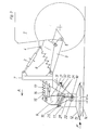
- a three-point linkage with an upper link (2) and lower links (3) is mounted at the top and bottom link points (4, 5) on the front of a tractor (1).
- Tension springs (6) act so that the three-point linkage is relieved.
- a support frame (7) belonging to a rotary mower is attached to the upper and lower links (2, 3).
- Firmly connected to the support frame (7) are two arms (8) (FIGS. 1 and 2) which point forwards and downwards from the support frame (7).
- a number of mowing drums (10) are mounted on a machine frame (9) and carry a casing (11), an annular collar (12) with knives (13) and a sliding plate (14).
- tension springs (15), elongated hole plates (16) and damping cylinders (17) establish a connection between the machine frame (9) and the support frame (7).
- support arms (18) are attached to the outer end faces of the machine frame (9). With their lower end, tabs (19) are connected in an articulated manner, which in turn are connected in an articulated manner at a pivot point (20) to the free ends of the arms (8).
- the tabs (19) are limited in their movement up and down by stops, not shown.
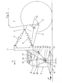
- the arms (27) receive a sleeve (28) at the lower end, which is penetrated by a transverse axis (29).
- Booms (31) are attached to the machine frame (9) and pass between the arms (21) to the rear. They carry stop bolts (32) which can interact with the back of the arms (21) and the stop cams (23) when reversing.
- Figures 5 and 6 show an embodiment which is similar to that of Figures 3 and 4.
- the arms (33) have angular slits at the lower end with a horizontal section (34) and a section (35) which rises backwards.
- the rollers (30) are at the front end of the slot (22).
- the stop bolts (32) then rest on the back of the arms (21) and on the stop cam (23).
- the mower is held in place and cannot impale itself in the ground. If the mower encounters an off-center obstacle while driving forward, a moment arises that turns the relevant side of the mower backwards. Because of the inclined position of the pendulum axis (25), the side of the mower that rotates backwards lifts up and can thus overcome the obstacle.
- the springs (6) are tensioned such that the rollers (30) lie in the kink of the angular slots (34, 35). For forward and backward travel, the same applies as described above. If the mower encounters an off-center obstacle, the roller (30) can rise on the corresponding side in the slot (35), as a result of which the mower side in question can move backwards and upwards. The effect is equivalent to that in the previously described versions.
Claims (17)
- Machine agricole, en particulier rotofaucheuse, comprenant un châssis porteur (7) pouvant être raccordé à l'attelage à trois points avant (2, 3) d'un tracteur et un ressort (6) par lequel une partie du poids de la machine peut être transférée au tracteur, et une monture (9) pour les outils de travail constitués par exemple sous forme de tambours de fauchage (10) qui exercent leur action au-dessous d'elle et à une faible hauteur au-dessus du sol et qui comprennent des collets annulaires (12) supportant des outils de coupe (13), monture qui est raccordée par une liaison articulée à axe transversal (19, 20, 28, 29) pouvant tourner à l'extrémité libre de bras (8, 21, 33) s'étendant vers le bas à partir du châssis porteur (7), moyennant quoi, dans la position de travail et dans le cas de la rencontre par exemple d'une force longitudinale (F) provoquée par un obstacle et agissant sensiblement à la hauteur des outils de travail (12, 13) de façon centrée ou excentrée par rapport au plan longitudinal médian, le côté de l'outil de fauchage sur lequel agit la force longitudinale (F) peut dévier vers le haut et vers l'arrière, caractérisée en ce que les bras (8, 21, 33) sont montés sur la châssis porteur (7) en étant prolongés vers le bas de manière que la liaison articulée (19, 20, 28, 29) soit située directement au-dessus des outils de travail (les collets annulaires 12) qui travaillent à proximité du sol à une certaine distance au-dessous de la monture (9).
- Machine agricole selon la revendication 1, caractérisée en ce que la liaison articulée est constituée par des pattes (19) qui sont reliées sur un côté de façon articulée à l'extrémité libre (20) des bras (8), s'étendent de là vers l'arrière et vers le bas dans la position de travail, et sont reliées à leur extrémité inférieure à des bras d'appui (18) de la monture (9).
- Machine agricole selon la revendication 2, caractérisée en ce que les bras (8), les bras d'appui (18) et les pattes (19) sont prévus des deux côtés de la monture (9) et les outils de travail (10) sont disposés entre ceux-ci sur la monture (9).
- Machine agricole selon les revendications 2 et 3, caractérisée en ce que la liberté de mouvement des pattes (19) est limitée vers le haut et vers le bas par des butées.
- Machine agricole selon la revendication 1, caractérisée en ce qu'il est prévu entre les tambours de fauchage (10) du centre un support (27, 36) qui s'étend vers le bas sensiblement au-dessous de la monture (9) et qui supporte à son extrémité inférieure un axe transversal (29) qui est en liaison avec les bras (21, 33) du châssis porteur (7).
- Machine agricole selon la revendication 5, caractérisée en ce que l'axe transversal (29) est monté entre les enveloppes (11) des tambours de fauchage (10) du centre et au-dessus des collets annulaires (12) des tambours de fauchage (10).
- Machine agricole selon les revendications 5 et 6, caractérisée en ce que le support (27) est relié à la monture (9) par l'intermédiaire d'un axe pendulaire oblique (25) qui est incliné du haut vers le bas et de l'avant vers l'arrière.
- Machine agricole selon la revendication 7, caractérisée en ce que l'inclinaison de l'axe pendulaire oblique (25) est d'au moins 25° par rapport au plan horizontal.
- Machine agricole selon les revendications 5 et 6, caractérisée en ce que les supports (36) sont solidaires de la monture (9).
- Machine agricole selon les revendications 5 et 6, caractérisée en ce que les bras (21, 33) comprennent des fentes (22, 34, 35) traversées par les extrémités libres de l'axe transversal (29).
- Machine agricole selon la revendication 10, caractérisée en ce que les fentes (22) des bras (21) horizontales.
- Machine agricole selon la revendication 10, caractérisée en ce que les fentes comprennent une section horizontale (34) et/ou une section inclinée (35) qui monte vers l'arrière.
- Machine agricole selon les revendications 10 à 12, caractérisée en ce que les extrémités libres de l'axe transversal (29) sont disposées, lors de la marche vers l'avant, aux extrémités arrière des sections horizontales (22, 34) des fentes, et dans le cas d'une marche vers l'arrière, dans les extrémités avant des sections horizontales (22, 34).
- Machine agricole selon l'une quelconque ou plusieurs des revendications précédentes, caractérisée en ce que sont prévues des butées (32) fixées à la monture (9), qui reposent pendant la marche arrière contre des saillies de butée (23) ou analogues des bras (21, 33) de manière que la monture (9) ne puisse pas tourner autour d'un axe transversal (29).
- Machine agricole selon l'une quelconque ou plusieurs des revendications précédentes, caractérisée en ce que des ressorts sont incorporés entre le bras supérieur (2) et les bras inférieurs (3) de la suspension à trois points, qui soulèvent le châssis porteur (7) en position de travail dans la mesure où la liaison articulée entre le châssis porteur (7) et la monture (9) le permettent.
- Machine agricole selon les revendications 5 et 6, caractérisée en ce que les bras (21, 33) et les supports (27, 36) sont prévus sur les deux côtés de la monture (9) et les tambours de fauchage (10) sont montés entre ceux-ci sur la monture (9).
- Machine agricole selon les revendications 1 et 5 à 16, caractérisée en ce que les liaisons articulées avec les axes transversaux (29) sont situées à une certaine distance (a) à l'arrière du plan vertical reliant les axes de rotation des tambours de fauchage (10), mais cependant à l'intérieur de la surface en projection de l'enveloppe (11) des tambours de fauchage (10).
Applications Claiming Priority (2)
| Application Number | Priority Date | Filing Date | Title |
|---|---|---|---|
| DE3914085A DE3914085A1 (de) | 1989-04-28 | 1989-04-28 | Landw. anbaugeraet, insbesondere kreiselmaehwerk |
| DE3914085 | 1989-04-28 |
Publications (2)
| Publication Number | Publication Date |
|---|---|
| EP0394830A1 EP0394830A1 (fr) | 1990-10-31 |
| EP0394830B1 true EP0394830B1 (fr) | 1992-12-02 |
Family
ID=6379695
Family Applications (1)
| Application Number | Title | Priority Date | Filing Date |
|---|---|---|---|
| EP90107396A Expired - Lifetime EP0394830B1 (fr) | 1989-04-28 | 1990-04-19 | Machine agricole, en particulier faucheuse, destinée à être montée sur un tracteur |
Country Status (4)
| Country | Link |
|---|---|
| EP (1) | EP0394830B1 (fr) |
| AT (1) | ATE82824T1 (fr) |
| DE (2) | DE3914085A1 (fr) |
| DK (1) | DK0394830T3 (fr) |
Families Citing this family (10)
| Publication number | Priority date | Publication date | Assignee | Title |
|---|---|---|---|---|
| DE8906546U1 (fr) * | 1989-05-27 | 1989-07-06 | Fella-Werke Gmbh, 8501 Feucht, De | |
| CH683057A5 (de) * | 1991-01-31 | 1994-01-14 | Walter Rogenmoser | Hilfseinrichtung für einen Traktor. |
| DE4212417A1 (de) * | 1992-04-14 | 1993-10-28 | Poettinger Alois Landmasch | Tragrahmen mit landwirtschaftlicher Erntemaschine, insbesondere Rotationsmähwerk |
| DE9315877U1 (de) * | 1993-10-18 | 1994-01-05 | Greenland Gmbh & Co Kg | Heuwerbungsmaschine |
| FR2716335B1 (fr) * | 1994-02-21 | 1997-05-16 | Massin Sa | Dispositif de débroussaillage et broyage forestier adaptable sur un véhicule automobile du type tracteur chenille, ou autre. |
| DE4415205C1 (de) * | 1994-04-30 | 1995-02-23 | Fortschritt Erntemaschinen | Anbaurahmen zum Frontanbau landwirtschaftlicher Arbeitsgeräte an ein Trägerfahrzeug |
| US5960614A (en) * | 1997-07-23 | 1999-10-05 | Jones; Hollis H. | Torsion hitch for tractor with fence mower |
| CA2986255A1 (fr) | 2015-05-19 | 2016-11-24 | Mchale Engineering | Appareil d'accouplement pour accoupler un outil agricole a un moteur d'entrainement |
| GB201701778D0 (en) * | 2017-02-03 | 2017-03-22 | Agco Int Gmbh | Sprayer boom suspension assembly |
| DE102019116934A1 (de) * | 2019-06-24 | 2020-12-24 | CLAAS Tractor S.A.S | Frontkraftheber sowie Arbeitsmaschine mit einem Frontkraftheber |
Family Cites Families (6)
| Publication number | Priority date | Publication date | Assignee | Title |
|---|---|---|---|---|
| FR2458981A1 (fr) * | 1979-06-19 | 1981-01-09 | Kuhn Sa | Bati de machine agricole |
| DE3022887A1 (de) * | 1980-06-19 | 1982-02-11 | Claas Saulgau GmbH, 7968 Saulgau | An die front-dreipunkaufhaengung eines schleppers anschliessbares landwirtschaftliches arbeitsgeraet |
| DE8204027U1 (de) * | 1982-02-13 | 1982-07-15 | Maschinenfabrik Rau Gmbh, 7315 Weilheim | Zinkenanordnung fuer grubbergeraete |
| DD239708A1 (de) * | 1985-07-30 | 1986-10-08 | Fortschritt Veb K | Kombinierte hydro-mechanische ueberlastsicherung und aushebevorrichtung fuer bodenbearbeitungswerkzeuge |
| DE8701093U1 (fr) * | 1987-01-23 | 1987-03-26 | Maschinenfabriken Bernard Krone Gmbh, 4441 Spelle, De | |
| DE8807406U1 (fr) * | 1988-06-07 | 1988-09-08 | Rabewerk Heinrich Clausing, 4515 Bad Essen, De |
-
1989
- 1989-04-28 DE DE3914085A patent/DE3914085A1/de not_active Withdrawn
-
1990
- 1990-04-19 DE DE9090107396T patent/DE59000528D1/de not_active Expired - Lifetime
- 1990-04-19 EP EP90107396A patent/EP0394830B1/fr not_active Expired - Lifetime
- 1990-04-19 AT AT90107396T patent/ATE82824T1/de not_active IP Right Cessation
- 1990-04-19 DK DK90107396.5T patent/DK0394830T3/da active
Also Published As
| Publication number | Publication date |
|---|---|
| ATE82824T1 (de) | 1992-12-15 |
| DE59000528D1 (de) | 1993-01-14 |
| EP0394830A1 (fr) | 1990-10-31 |
| DK0394830T3 (da) | 1993-03-22 |
| DE3914085A1 (de) | 1990-10-31 |
Similar Documents
| Publication | Publication Date | Title |
|---|---|---|
| EP0234585B1 (fr) | Moissonneuse-batteuse | |
| EP0045060B1 (fr) | Fixation pour le support flexible d'une section à disques du cadre d'un pulvériseur à disques ou d'outils semblables | |
| EP0475021B1 (fr) | Tondeuse, en particulier tondeuse frontale | |
| DE2527645C3 (de) | Erntemaschine für in Reihe stehende Halmfrüchte | |
| DE2948664C2 (de) | Landmaschine | |
| EP0394830B1 (fr) | Machine agricole, en particulier faucheuse, destinée à être montée sur un tracteur | |
| DE19818960A1 (de) | Aufhängung eines Vorsatzes | |
| DE7523511U (de) | Aufsatteldrehpflug mit einer ueberlastsicherung der verbindung zwischen bodenbearbeitungswerkzeugen und ihren tragrahmen | |
| DE2630493C3 (de) | An die Dreipunktaufhängung eines Schleppers anschließbarer Kreiselmäher | |
| EP1266551B1 (fr) | Appareil de travail pour le montage sur véhicule | |
| EP0933016A1 (fr) | Dispositif de support et véhicule pour l'entretien du terrain | |
| DE2725233C2 (de) | Bodenbearbeitungsmaschine | |
| DE2632002C2 (de) | Mähmaschine | |
| DE2528928A1 (de) | Landwirtschaftliches bodenbearbeitungsgeraet, insbesondere kruemler | |
| DE2932752C2 (fr) | ||
| DE3233560C1 (de) | Frontmähwerk | |
| EP0630553A1 (fr) | Arrangement d'entraînement d'un appareil, pour une combinaison véhicule-appareil | |
| DE3116984C2 (fr) | ||
| DE1927793A1 (de) | Kombinierte Abtast-Maehmaschine | |
| DE2614652A1 (de) | Anbaumaehvorrichtung | |
| DE2945062A1 (de) | Bodenbearbeitungsmaschine | |
| EP0566033A1 (fr) | Cadre support pour machine de récolte, en particulier faucheuse rotative | |
| EP0022283A1 (fr) | Dispositif pour éviter un effort excessif de la connection entre deux parties d'une machine agricole | |
| DE4103011C2 (de) | Mäh- oder Heumaschine | |
| DE2648293C2 (de) | Zinkenanordnung an einem Bodenbearbeitungsgerät |
Legal Events
| Date | Code | Title | Description |
|---|---|---|---|
| PUAI | Public reference made under article 153(3) epc to a published international application that has entered the european phase |
Free format text: ORIGINAL CODE: 0009012 |
|
| AK | Designated contracting states |
Kind code of ref document: A1 Designated state(s): AT CH DE DK FR GB IT LI NL |
|
| 17P | Request for examination filed |
Effective date: 19901218 |
|
| 17Q | First examination report despatched |
Effective date: 19910131 |
|
| ITF | It: translation for a ep patent filed |
Owner name: DE DOMINICIS & MAYER S. |
|
| GRAA | (expected) grant |
Free format text: ORIGINAL CODE: 0009210 |
|
| AK | Designated contracting states |
Kind code of ref document: B1 Designated state(s): AT CH DE DK FR GB IT LI NL |
|
| REF | Corresponds to: |
Ref document number: 82824 Country of ref document: AT Date of ref document: 19921215 Kind code of ref document: T |
|
| GBT | Gb: translation of ep patent filed (gb section 77(6)(a)/1977) |
Effective date: 19921130 |
|
| REF | Corresponds to: |
Ref document number: 59000528 Country of ref document: DE Date of ref document: 19930114 |
|
| REG | Reference to a national code |
Ref country code: DK Ref legal event code: T3 |
|
| ET | Fr: translation filed | ||
| PLBE | No opposition filed within time limit |
Free format text: ORIGINAL CODE: 0009261 |
|
| STAA | Information on the status of an ep patent application or granted ep patent |
Free format text: STATUS: NO OPPOSITION FILED WITHIN TIME LIMIT |
|
| 26N | No opposition filed | ||
| REG | Reference to a national code |
Ref country code: GB Ref legal event code: IF02 |
|
| PGFP | Annual fee paid to national office [announced via postgrant information from national office to epo] |
Ref country code: GB Payment date: 20030324 Year of fee payment: 14 |
|
| PGFP | Annual fee paid to national office [announced via postgrant information from national office to epo] |
Ref country code: NL Payment date: 20030423 Year of fee payment: 14 |
|
| PG25 | Lapsed in a contracting state [announced via postgrant information from national office to epo] |
Ref country code: GB Free format text: LAPSE BECAUSE OF NON-PAYMENT OF DUE FEES Effective date: 20040419 |
|
| PG25 | Lapsed in a contracting state [announced via postgrant information from national office to epo] |
Ref country code: NL Free format text: LAPSE BECAUSE OF NON-PAYMENT OF DUE FEES Effective date: 20041101 |
|
| GBPC | Gb: european patent ceased through non-payment of renewal fee |
Effective date: 20040419 |
|
| NLV4 | Nl: lapsed or anulled due to non-payment of the annual fee |
Effective date: 20041101 |
|
| PG25 | Lapsed in a contracting state [announced via postgrant information from national office to epo] |
Ref country code: IT Free format text: LAPSE BECAUSE OF NON-PAYMENT OF DUE FEES Effective date: 20050419 |
|
| PGFP | Annual fee paid to national office [announced via postgrant information from national office to epo] |
Ref country code: DK Payment date: 20090423 Year of fee payment: 20 |
|
| PGFP | Annual fee paid to national office [announced via postgrant information from national office to epo] |
Ref country code: DE Payment date: 20080903 Year of fee payment: 20 Ref country code: AT Payment date: 20090423 Year of fee payment: 20 Ref country code: FR Payment date: 20090420 Year of fee payment: 20 |
|
| PGFP | Annual fee paid to national office [announced via postgrant information from national office to epo] |
Ref country code: CH Payment date: 20090427 Year of fee payment: 20 |
|
| REG | Reference to a national code |
Ref country code: CH Ref legal event code: PL |
|
| REG | Reference to a national code |
Ref country code: DK Ref legal event code: EUP |
|
| PG25 | Lapsed in a contracting state [announced via postgrant information from national office to epo] |
Ref country code: DE Free format text: LAPSE BECAUSE OF EXPIRATION OF PROTECTION Effective date: 20100419 |