US4066132A - Disk harrow with beam member suspended by u-shaped springs - Google Patents
Disk harrow with beam member suspended by u-shaped springs Download PDFInfo
- Publication number
- US4066132A US4066132A US05/659,596 US65959676A US4066132A US 4066132 A US4066132 A US 4066132A US 65959676 A US65959676 A US 65959676A US 4066132 A US4066132 A US 4066132A
- Authority
- US
- United States
- Prior art keywords
- beam member
- spring
- flat
- section
- disk
- Prior art date
- Legal status (The legal status is an assumption and is not a legal conclusion. Google has not performed a legal analysis and makes no representation as to the accuracy of the status listed.)
- Expired - Lifetime
Links
Images

Classifications
-
- A—HUMAN NECESSITIES
- A01—AGRICULTURE; FORESTRY; ANIMAL HUSBANDRY; HUNTING; TRAPPING; FISHING
- A01B—SOIL WORKING IN AGRICULTURE OR FORESTRY; PARTS, DETAILS, OR ACCESSORIES OF AGRICULTURAL MACHINES OR IMPLEMENTS, IN GENERAL
- A01B21/00—Harrows with rotary non-driven tools
- A01B21/08—Harrows with rotary non-driven tools with disc-like tools
-
- A—HUMAN NECESSITIES
- A01—AGRICULTURE; FORESTRY; ANIMAL HUSBANDRY; HUNTING; TRAPPING; FISHING
- A01B—SOIL WORKING IN AGRICULTURE OR FORESTRY; PARTS, DETAILS, OR ACCESSORIES OF AGRICULTURAL MACHINES OR IMPLEMENTS, IN GENERAL
- A01B61/00—Devices for, or parts of, agricultural machines or implements for preventing overstrain
- A01B61/04—Devices for, or parts of, agricultural machines or implements for preventing overstrain of the connection between tools and carrier beam or frame
Definitions
- the present invention relates generally to agricultural implements, and more particularly to means for resiliently mounting a gang of earthworking tools on the mobile frame of an agricultural implement.
- Modern agricultural implements such as disk tillers and disk harrows are becoming wider, longer and heavier as the farmer seeks to improve his productivity and profitability.
- shocks encountered by individual implement tools increase, particularly when rocky or stumpy fields are worked.
- U.S. Pat. No. 3,706,345 a U-shaped torsion bar is utilized between the gang standard and standard support shaft to provide a cushioning effect in the vertical and fore-and-aft directions.
- U.S. Pat. No. 3,640,348 there is disclosed a resilient standard supporting a disk gang shaft upon which the disk blades are rotatably mounted. This resilient standard cushions shocks absorbed in a transverse direction as well as fore and aft and vertical. However, the shocks are transmitted directly to the shaft supporting the disk blades. When the disk gang shaft or bolt has to absorb shocks encountered in operating, it may bend or after repeated shock loading may fracture. Further, the working tools or disk blades often become misaligned resulting in premature failure of the disk bearings.
- the invention comprises a tubular member carried by and supported on a disk implement frame and a pair of spaced-apart rearwardly opening generally C-shaped flat springs suspended from the tubular member and secured to a tubular gang frame which in turn supports a gang of disk blades.
- FIG. 1 is a perspective view illustrating a resiliently suspended disk gang.
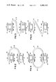
- FIG. 2 is an enlarged side view of a C-shaped resilient suspension.
- FIG. 3 is a view similar to FIG. 2 showing a modified form of the invention.
- FIG. 4 is a view similar to FIG. 2 showing a further modified form of the invention.
- FIG. 5 is a view similar to FIG. 2 showing still a further form of the invention.
- FIG. 1 a disk harrow frame 10 with ground wheels, one of which is shown at 12, which support the frame 10 at a constant height relative to the ground, and a transversely positioned disk gang 14 suspended from the frame 10.
- the gang 14 includes a plurality of earthworking disk blades 16.
- any type of tool supported in a gang could utilize the invention.
- the gang 14 is comprised of a similar second beam member or gang frame tube 22 having a pair of spaced-apart support arms 24 depending therefrom.
- a gang bolt or shaft 26 is supported from the arms 24 and has rotatably mounted thereon the spaced-apart disk blades 16.
- each gang 14 Resiliently suspending each gang 14 from its respective first tubular member 20 are spaced-apart rearwardly opening flat springs 28.
- each spring 28 includes upper and lower flat portions 30 and 32 respectively joined by a vertical fore-and-aft opening C-shaped portion 34.
- a flat spring is utilized since the majority of shocks encountered will cause the gang 14 to move vertically and/or in a fore-and-aft direction. However, since shocks will also be encountered which will result in transverse forces, a spring capable of dissipating tranverse forces is provided.
- a first bracket 36 secures the upper flat portion 30 of each spring 28 to the upper surface of the first tubular member 20 and a second similar bracket 38 secures the lower flat portion 32 of each spring 28 to the upper surface of the gang frame tube or second tubular member 22.
- Each bracket 36 and 38 includes upper and lower flat plate members 40 and 42 respectively.
- the upper plate member 40 cooperates with tubular member 20 or 22 to clamp spring flat portions 30 and 32 therebetween.
- Bolts 44 secure the parts together and the rearward most bolt passes through an opening in the C-shaped spring flat portion to secure it between the bracket plates.
- a bracket flat plate member having a horizontal surface area greater than the tubular member bottom surface is provided.
- the first and second tubular members 20 and 22 are mounted generally parallel and generally transverse to the direction of movement.
- Each C-shaped spring 28 is secured between the tubular members 20 and 22 and opens in a fore-and-aft direction generally perpendicular to the line defined by the tubular members 20 and 22. While the suspension spring 28 utilized in the current embodiment opens to the rear, it is also arranged to absorb transverse shock loading and yet return the disks 16 to their original path of operation. Were the disks 16 held rigid in a transverse direction, damage could more easily be caused to the disk blades 16 and structural members of the harrow.
- each individual gang 14 will penetrate the ground to a generally uniform depth since each gang 14 is resiliently suspended and can therefore conform to ground contours.
- FIGS. 3, 4 and 5 Illustrated in FIGS. 3, 4 and 5 are modifications of the suspension spring utilized in the invention.
- FIG. 2 illustrates a side view of the spring utilized while FIG. 3 illustrates an S-shaped flat spring opening along generally fore-and-aft lines.
- FIG. 4 illustrates an O-shaped flat spring designed to also be suspended along generally fore-and-aft extending lines.
- FIG. 5, which illustrates a Z-shaped spring could also be used in place of the preferred spring illustrated in FIG. 2.
- Each of the illustrated spring modifications are comprised of flat spring material designed to cushion vertical and fore-and-aft forces and also incur, absorb and dissipate transverse forces without incurring structural damage to the spring gang or frame structures.
Abstract
Disk gangs are resiliently suspended from an implement frame by retroverted flat spring members. Flat surfaces of the springs are oriented perpendicularly to the disk blade shaft to thereby permit vertical and fore-and-aft flexing of the disk gangs as obstacles are encountered and yet minimize lateral movement of the gangs to retain gang blade alignment between front and rearwardly positioned disk gangs.
Description
The present invention relates generally to agricultural implements, and more particularly to means for resiliently mounting a gang of earthworking tools on the mobile frame of an agricultural implement.
Modern agricultural implements such as disk tillers and disk harrows are becoming wider, longer and heavier as the farmer seeks to improve his productivity and profitability. As the weight of these implements and frames increases, it becomes desirable to mount the tool gangs on the frame in a resilient rather than rigid manner, so that the gangs independently yield to insure that uneven ground is worked to a uniform depth. Additionally, as the width of implement frames increases, shocks encountered by individual implement tools increase, particularly when rocky or stumpy fields are worked.
Various means have been devised for resiliently mounting a gang of earthworking tools on an implement frame. For example, disclosed in U.S. Pat. No. 3,706,345, a U-shaped torsion bar is utilized between the gang standard and standard support shaft to provide a cushioning effect in the vertical and fore-and-aft directions. In U.S. Pat. No. 3,640,348 there is disclosed a resilient standard supporting a disk gang shaft upon which the disk blades are rotatably mounted. This resilient standard cushions shocks absorbed in a transverse direction as well as fore and aft and vertical. However, the shocks are transmitted directly to the shaft supporting the disk blades. When the disk gang shaft or bolt has to absorb shocks encountered in operating, it may bend or after repeated shock loading may fracture. Further, the working tools or disk blades often become misaligned resulting in premature failure of the disk bearings.
It is therefore a principal object of the present invention to provide a means for resiliently suspending a gang of earthworking tools from an implement frame whereby shock impacts received in vertical, transverse and fore-and-aft directions are absorbed and dissipated to minimize structural damage to the gang and implement.
It is a further object to provide a compact means for resiliently suspending a gang of eathworking tools wherein the buildup of trash and other objects during operation is minimized. It is also an object to provide a simple and reliable means of suspension which is inexpensive to manufacture and maintain.
In pursuance of these and other objects, the invention comprises a tubular member carried by and supported on a disk implement frame and a pair of spaced-apart rearwardly opening generally C-shaped flat springs suspended from the tubular member and secured to a tubular gang frame which in turn supports a gang of disk blades.
FIG. 1 is a perspective view illustrating a resiliently suspended disk gang.
FIG. 2 is an enlarged side view of a C-shaped resilient suspension.
FIG. 3 is a view similar to FIG. 2 showing a modified form of the invention.
FIG. 4 is a view similar to FIG. 2 showing a further modified form of the invention.
FIG. 5 is a view similar to FIG. 2 showing still a further form of the invention.
Referring now to the drawings, there is illustrated in FIG. 1 a disk harrow frame 10 with ground wheels, one of which is shown at 12, which support the frame 10 at a constant height relative to the ground, and a transversely positioned disk gang 14 suspended from the frame 10. The gang 14 includes a plurality of earthworking disk blades 16. However, any type of tool supported in a gang could utilize the invention.
Supported on the upper surface 18 of the mobile frame 10 is an elongated first tubular or beam member 20. The gang 14 is comprised of a similar second beam member or gang frame tube 22 having a pair of spaced-apart support arms 24 depending therefrom. A gang bolt or shaft 26 is supported from the arms 24 and has rotatably mounted thereon the spaced-apart disk blades 16.
Resiliently suspending each gang 14 from its respective first tubular member 20 are spaced-apart rearwardly opening flat springs 28.
As illustrated in FIG. 1, each spring 28 includes upper and lower flat portions 30 and 32 respectively joined by a vertical fore-and-aft opening C-shaped portion 34. A flat spring is utilized since the majority of shocks encountered will cause the gang 14 to move vertically and/or in a fore-and-aft direction. However, since shocks will also be encountered which will result in transverse forces, a spring capable of dissipating tranverse forces is provided.
A first bracket 36 secures the upper flat portion 30 of each spring 28 to the upper surface of the first tubular member 20 and a second similar bracket 38 secures the lower flat portion 32 of each spring 28 to the upper surface of the gang frame tube or second tubular member 22. By securing the spring 28 to the adjacent surface of the tubular members 20 and 22, greater clearance is provided to minimize trash buildup encountered during the operation. Each bracket 36 and 38 includes upper and lower flat plate members 40 and 42 respectively. The upper plate member 40 cooperates with tubular member 20 or 22 to clamp spring flat portions 30 and 32 therebetween. Bolts 44 secure the parts together and the rearward most bolt passes through an opening in the C-shaped spring flat portion to secure it between the bracket plates. To provide greater support for the spring flat portions during operations, a bracket flat plate member having a horizontal surface area greater than the tubular member bottom surface is provided.
The first and second tubular members 20 and 22 are mounted generally parallel and generally transverse to the direction of movement. Each C-shaped spring 28 is secured between the tubular members 20 and 22 and opens in a fore-and-aft direction generally perpendicular to the line defined by the tubular members 20 and 22. While the suspension spring 28 utilized in the current embodiment opens to the rear, it is also arranged to absorb transverse shock loading and yet return the disks 16 to their original path of operation. Were the disks 16 held rigid in a transverse direction, damage could more easily be caused to the disk blades 16 and structural members of the harrow.
In operation, the farmer will raise the ground-engaging wheels 12 thereby lowering the disk gang 14 to the ground. As the disk frame 10 and its earthworking tools are towed across the field, each individual gang 14 will penetrate the ground to a generally uniform depth since each gang 14 is resiliently suspended and can therefore conform to ground contours.
As occasionally happens, rock, stumps and other solid materials are encountered during the disking operation. When such an object is encountered by a disk blade 16, the forces resulting from the shock impact will be transferred through the blade 16 to the shaft 26, through the arms 24 and out the second tubular member 22 to the suspension spring 28. Were the disk blade 16 rigidly mounted with the frame 10, the shock impact could not be cushioned and the frequency and likelihood of structural damage resulting would be increased. As solid objects are encountered by the disk blades 16, the gang 14 is suspended for movement to the rear and up, or transversely to the side as may become necessary to cushion all the forces encountered in the shock.
Illustrated in FIGS. 3, 4 and 5 are modifications of the suspension spring utilized in the invention. FIG. 2 illustrates a side view of the spring utilized while FIG. 3 illustrates an S-shaped flat spring opening along generally fore-and-aft lines. FIG. 4 illustrates an O-shaped flat spring designed to also be suspended along generally fore-and-aft extending lines. FIG. 5, which illustrates a Z-shaped spring could also be used in place of the preferred spring illustrated in FIG. 2. Each of the illustrated spring modifications are comprised of flat spring material designed to cushion vertical and fore-and-aft forces and also incur, absorb and dissipate transverse forces without incurring structural damage to the spring gang or frame structures.
Claims (2)
1. In a disk harrow comprising: a mobile frame having laterally spaced apart frame members; a first beam member transversely fixed to the frame in overlying relationship thereto and having a rectangular cross section with horizontally extending upper and lower flat surfaces; a second beam member beneath and generally parallel to the first beam member, said second beam member also having a rectangular cross section with horizontally extending upper and lower flat surfaces; a pair of spaced apart support arms attached to the second beam member and depending therefrom; a plurality of blades mounted on a common shaft carried by the support arms; spaced apart U-shaped spring members disposed between the laterally spaced apart frame members, the base section of each spring member extending forwardly from the beam members and generally vertically therebetween, with the leg section of each spring member extending rearwardly from the base section and having flat upper and lower portions, each flat portion disposed adjacent a horizontal surface of a respective beam member; and clamp means bearing against the opposite horizontal surfaces of each beam member for securing the respective flat section of the spring member thereto.
2. The invention defined in claim 1 wherein the clamp means are further characterized as having upper and lower horizontal plate members secured together, one plate member adjacent a horizontal flat portion of a respective spring member and the other plate adjacent a respective surface of a respective beam member.
Priority Applications (2)
| Application Number | Priority Date | Filing Date | Title |
|---|---|---|---|
| US05/659,596 US4066132A (en) | 1976-02-20 | 1976-02-20 | Disk harrow with beam member suspended by u-shaped springs |
| CA271,995A CA1066110A (en) | 1976-02-20 | 1977-02-17 | Means for resiliently mounting a disk gang |
Applications Claiming Priority (1)
| Application Number | Priority Date | Filing Date | Title |
|---|---|---|---|
| US05/659,596 US4066132A (en) | 1976-02-20 | 1976-02-20 | Disk harrow with beam member suspended by u-shaped springs |
Publications (1)
| Publication Number | Publication Date |
|---|---|
| US4066132A true US4066132A (en) | 1978-01-03 |
Family
ID=24645991
Family Applications (1)
| Application Number | Title | Priority Date | Filing Date |
|---|---|---|---|
| US05/659,596 Expired - Lifetime US4066132A (en) | 1976-02-20 | 1976-02-20 | Disk harrow with beam member suspended by u-shaped springs |
Country Status (2)
| Country | Link |
|---|---|
| US (1) | US4066132A (en) |
| CA (1) | CA1066110A (en) |
Cited By (15)
| Publication number | Priority date | Publication date | Assignee | Title |
|---|---|---|---|---|
| EP0045060A1 (en) * | 1980-07-25 | 1982-02-03 | Deere & Company | Holding device for the flexible mounting of a disk gang to the frame of a disk harrow or the like |
| US4396070A (en) * | 1981-07-09 | 1983-08-02 | Harley Brandner | Pivotal disc gang section |
| EP0089053A1 (en) * | 1982-03-15 | 1983-09-21 | Deere & Company | Soil tilling implement |
| US4407372A (en) * | 1981-09-17 | 1983-10-04 | International Harvester Co. | Disk harrow with cushion gang |
| US4762182A (en) * | 1983-07-13 | 1988-08-09 | Reimann Harold J | Auxiliary mounting device for cultivating implements |
| US5042590A (en) * | 1990-09-20 | 1991-08-27 | Deere & Company | Tapered C-spring for a disk harrow |
| US6158523A (en) * | 1998-10-30 | 2000-12-12 | Sunflower Manufacturing Co., Inc. | Agricultural disc mounting system and method |
| WO2004004438A1 (en) * | 2002-07-05 | 2004-01-15 | Våderstad-Verken Ab | Soil preparation unit |
| FR2855714A1 (en) * | 2003-06-05 | 2004-12-10 | Auf Der Landwehr Gmbh | Seed drill has disks mounted on beams which are attached to machine frame by spiral leaf springs |
| US20060061022A1 (en) * | 2004-09-20 | 2006-03-23 | Hung-Shen Chang | Shock-absorbing device for wheeled vehicle |
| US7131501B1 (en) | 2005-08-17 | 2006-11-07 | Standens Ltd. | Disk harrow with U-shaped cushions of tapered round section |
| US20090025946A1 (en) * | 2007-07-23 | 2009-01-29 | Kovach Michael G | Crop residue and soil conditioning agricultural implement |
| US20090090523A1 (en) * | 2007-10-08 | 2009-04-09 | Newman Michael R | Disc frame vibration dampening system |
| US20150292591A1 (en) * | 2012-11-26 | 2015-10-15 | Dal-Bo A/S | A device for stubble treatment and a vibration-absorbing arrangement thereof |
| US20150366125A1 (en) * | 2014-06-24 | 2015-12-24 | Deere & Company | Combination c-shaped spring and system |
Citations (5)
| Publication number | Priority date | Publication date | Assignee | Title |
|---|---|---|---|---|
| US564133A (en) * | 1896-07-14 | Woodlltf | ||
| US2750861A (en) * | 1952-07-21 | 1956-06-19 | Ford Motor Co | Mounting for disc type soil working tools |
| US2985248A (en) * | 1960-07-22 | 1961-05-23 | Irwin W Richardson | Gang harrow |
| US3576216A (en) * | 1969-03-21 | 1971-04-27 | Allis Chalmers Mfg Co | Spring mounting for disc harrow blades |
| US3640348A (en) * | 1970-02-02 | 1972-02-08 | Kewanee Mach & Conveyor Co | S-shaped standard |
-
1976
- 1976-02-20 US US05/659,596 patent/US4066132A/en not_active Expired - Lifetime
-
1977
- 1977-02-17 CA CA271,995A patent/CA1066110A/en not_active Expired
Patent Citations (5)
| Publication number | Priority date | Publication date | Assignee | Title |
|---|---|---|---|---|
| US564133A (en) * | 1896-07-14 | Woodlltf | ||
| US2750861A (en) * | 1952-07-21 | 1956-06-19 | Ford Motor Co | Mounting for disc type soil working tools |
| US2985248A (en) * | 1960-07-22 | 1961-05-23 | Irwin W Richardson | Gang harrow |
| US3576216A (en) * | 1969-03-21 | 1971-04-27 | Allis Chalmers Mfg Co | Spring mounting for disc harrow blades |
| US3640348A (en) * | 1970-02-02 | 1972-02-08 | Kewanee Mach & Conveyor Co | S-shaped standard |
Cited By (22)
| Publication number | Priority date | Publication date | Assignee | Title |
|---|---|---|---|---|
| US4333535A (en) * | 1980-07-25 | 1982-06-08 | Deere & Company | Disc standard assembly |
| EP0045060A1 (en) * | 1980-07-25 | 1982-02-03 | Deere & Company | Holding device for the flexible mounting of a disk gang to the frame of a disk harrow or the like |
| US4396070A (en) * | 1981-07-09 | 1983-08-02 | Harley Brandner | Pivotal disc gang section |
| US4407372A (en) * | 1981-09-17 | 1983-10-04 | International Harvester Co. | Disk harrow with cushion gang |
| EP0089053A1 (en) * | 1982-03-15 | 1983-09-21 | Deere & Company | Soil tilling implement |
| US4492272A (en) * | 1982-03-15 | 1985-01-08 | Deere & Company | Tillage implement and improved gang assembly therefor |
| US4762182A (en) * | 1983-07-13 | 1988-08-09 | Reimann Harold J | Auxiliary mounting device for cultivating implements |
| US5042590A (en) * | 1990-09-20 | 1991-08-27 | Deere & Company | Tapered C-spring for a disk harrow |
| USRE38974E1 (en) | 1998-10-30 | 2006-02-14 | Agco Corporation | Agricultural disc mounting system and method |
| US6158523A (en) * | 1998-10-30 | 2000-12-12 | Sunflower Manufacturing Co., Inc. | Agricultural disc mounting system and method |
| WO2004004438A1 (en) * | 2002-07-05 | 2004-01-15 | Våderstad-Verken Ab | Soil preparation unit |
| FR2855714A1 (en) * | 2003-06-05 | 2004-12-10 | Auf Der Landwehr Gmbh | Seed drill has disks mounted on beams which are attached to machine frame by spiral leaf springs |
| US20060061022A1 (en) * | 2004-09-20 | 2006-03-23 | Hung-Shen Chang | Shock-absorbing device for wheeled vehicle |
| US7131501B1 (en) | 2005-08-17 | 2006-11-07 | Standens Ltd. | Disk harrow with U-shaped cushions of tapered round section |
| US20090025946A1 (en) * | 2007-07-23 | 2009-01-29 | Kovach Michael G | Crop residue and soil conditioning agricultural implement |
| US7743844B2 (en) * | 2007-07-23 | 2010-06-29 | Cnh America Llc | Crop residue and soil conditioning agricultural implement |
| US20090090523A1 (en) * | 2007-10-08 | 2009-04-09 | Newman Michael R | Disc frame vibration dampening system |
| US7578356B2 (en) | 2007-10-08 | 2009-08-25 | Cnh America Llc | Disc frame vibration dampening system |
| US20150292591A1 (en) * | 2012-11-26 | 2015-10-15 | Dal-Bo A/S | A device for stubble treatment and a vibration-absorbing arrangement thereof |
| US9500246B2 (en) * | 2012-11-26 | 2016-11-22 | Dal-Bo A/S | Device for stubble treatment and a vibration-absorbing arrangement thereof |
| US20150366125A1 (en) * | 2014-06-24 | 2015-12-24 | Deere & Company | Combination c-shaped spring and system |
| US9769974B2 (en) * | 2014-06-24 | 2017-09-26 | Deere & Company | Combination C-shaped spring and system |
Also Published As
| Publication number | Publication date |
|---|---|
| CA1066110A (en) | 1979-11-13 |
Similar Documents
| Publication | Publication Date | Title |
|---|---|---|
| US4066132A (en) | Disk harrow with beam member suspended by u-shaped springs | |
| US5964300A (en) | Wear shin for a tillage implement | |
| US4194575A (en) | Multiple rotary hoe and support arms | |
| ES8406836A1 (en) | Soil tilling implement. | |
| US3878901A (en) | Extra heavy duty multi-disc harrow with automatic level control | |
| US3759332A (en) | Extra heavy duty multi-disc harrow with automatic level control | |
| US2765609A (en) | Disk harrow including a wheel attachment | |
| US3001590A (en) | Unit carriers | |
| US3292714A (en) | Wheel type offset disk harrow | |
| US3193306A (en) | Cultivator hitch | |
| US3552497A (en) | Unitized side-by-side tractor and ripper combination | |
| US2752837A (en) | Four row cultivator | |
| US2257650A (en) | Agricultural machine | |
| US3825073A (en) | Spring cushion shank mounting assembly | |
| US3442336A (en) | Flexible mounting for disk harrow gang | |
| US2727453A (en) | Implement for alternate strip tilling | |
| US2332616A (en) | Cultivator | |
| GB549114A (en) | Improvements in or relating to agricultural implements | |
| US3151683A (en) | Cultivator attachment for rotary hoe | |
| US2456465A (en) | Convertible disk plow | |
| US4429750A (en) | Ridge leveler | |
| US2952325A (en) | Disk gang mounting means | |
| US3173494A (en) | Overload release trip for cultivator shanks | |
| US3190366A (en) | Agricultural implement | |
| US2172985A (en) | Implement |