US3576216A - Spring mounting for disc harrow blades - Google Patents

Spring mounting for disc harrow blades Download PDF

Info

Publication number
US3576216A
US3576216A US809176A US3576216DA US3576216A US 3576216 A US3576216 A US 3576216A US 809176 A US809176 A US 809176A US 3576216D A US3576216D A US 3576216DA US 3576216 A US3576216 A US 3576216A
Authority
US
United States
Prior art keywords
disc
discs
ground working
spring steel
bolt
Prior art date
Legal status (The legal status is an assumption and is not a legal conclusion. Google has not performed a legal analysis and makes no representation as to the accuracy of the status listed.)
Expired - Lifetime
Application number
US809176A
Inventor
Willard H Tanke
Current Assignee (The listed assignees may be inaccurate. Google has not performed a legal analysis and makes no representation or warranty as to the accuracy of the list.)
Deutz Allis Corp
Original Assignee
Allis Chalmers Corp
Priority date (The priority date is an assumption and is not a legal conclusion. Google has not performed a legal analysis and makes no representation as to the accuracy of the date listed.)
Filing date
Publication date
Application filed by Allis Chalmers Corp filed Critical Allis Chalmers Corp
Application granted granted Critical
Publication of US3576216A publication Critical patent/US3576216A/en
Assigned to DEUTZ-ALLIS CORPORATION A CORP OF DE reassignment DEUTZ-ALLIS CORPORATION A CORP OF DE ASSIGNMENT OF ASSIGNORS INTEREST. Assignors: ALLIS-CHALMER CORPORATION A DE CORP
Anticipated expiration legal-status Critical
Expired - Lifetime legal-status Critical Current

Links

Images

Classifications

    • AHUMAN NECESSITIES
    • A01AGRICULTURE; FORESTRY; ANIMAL HUSBANDRY; HUNTING; TRAPPING; FISHING
    • A01BSOIL WORKING IN AGRICULTURE OR FORESTRY; PARTS, DETAILS, OR ACCESSORIES OF AGRICULTURAL MACHINES OR IMPLEMENTS, IN GENERAL
    • A01B23/00Elements, tools, or details of harrows
    • A01B23/06Discs; Scrapers for cleaning discs; Sharpening attachments; Lubrication of bearings

Definitions

  • disc harrow implement by providing supports for the discs in the nature of multileaf springs so that upon contacting an obstruction the outer portion of the disc will flex adjacent the edge of the outer spring leaf and if the load to which the disc is being subjected is even greater then the disc will also flex about the edge of the next spring leaf closer to the center of the disc and the load is heavy enough the disc will also flex about the outer periphery of the spacers at which point the disc is mounted substantially rigid, and] some deflection may take place in the standard supporting the discs and their gang bolt.
  • the present invention relates generally to ground working disc implements and has for its general object the provision of novel means for supporting the discs whereby the breakage of discs and the supports therefor due to striking of stones and rocks when the discs are drawn through soil are substantially reduced or eliminated.
  • Supporting means for the discs such as spools, shafts and bearing hangers are heavier imposing even greater loads on the discs.
  • FIG. I is a fragmentary sectional elevation of a disc gang of an implement embodying the invention.
  • FIG. 2 is an enlarged fragment of FIG. 1;
  • FIG. 3 is a view similar to FIG. 2 showing a modification
  • FIG. 4 is an end view of the embodiment shown in FIG. 1.
  • the disc gang indicated in its entirety by the reference numeral 10 includes a frame 12 to which are fixed supporting standards 14 (only one of which is shown) by means of U-bolt 16.
  • the lower ends of the standards carry bearings I8 (FIG. 4) which are joumaled in cylindrical bearing sleeves 20, the former having apertures 22 of hexagon cross section to receive a hexagon gang bolt 24.
  • Disposed on the bolt 24 are concave-convex ground working discs 26, each of which is provided with a hexagon opening 28 adapted to receive the bolt 24.
  • the opening 28 is only large enough to pennit axial sliding movement of the disc on the bolt.
  • spacing spool 30 having an interior passage 32 of hexagon cross section adapted to slide over the bolt 24 to prevent rotation of the spool relative to the bolt 24.
  • Adjacent the right-hand end of frame 12 bearing spool 34 (FIG. I) is provided having an interior hexagon passageway 36 of a size to receive bolt 24.
  • a spring steel disc 40 is positioned between end face of spool 30 and a second larger spring steel disc 42 which is mounted to contact one side of disc 26.
  • a spring steel disc 44 is positioned between the end of spacer spool 34 and the other side of disc 26.
  • Disc 44 is identical "to disc 40, however, if desired; disc 40 may be dished to conform to the curvature of disc 26 and disc 44 may be flat as indicated in FIG. 3 but will resiliently conform to the shape of blade 26 when bolt 24 has been tightened. Blade 44 in FIG. 3 thus functions like a Belleville washer.
  • disc 26 strikes a rock or stone when it is being drawn through a soil bed, disc 26 will deflect about the outer periphery of disc 42 and if the contact between rock andblade 26 is severe enough then the blade 26 will additionally deflect about the peripheral edge of blade 40 and if severe enough, about the outer edge of spacer spool 30, much in themanner of a leaf spring. And if the contact between rock and blade 26 is severe enough, standard members 14 will also flex to minimize damage to blade 26.
  • standard 14 (FIG. 4) is tapered and is provided with a relatively large base portion for attachment to frame I2 and its opposite end is much smaller so that standard 14 is in the nature of a cantilever beam of uniform strength.
  • a ground working tool a gang bolt, a ground working disc havingan aperture through which saidbolt extends, a plurality of spring steel discs mounted on said bolt with at least one of said spring steel discs being mounted on each side of said ground working disc in contacting relation thereto, a pair of spacer spools mounted on said bolt outboard from said spring steel discs for comparing said spring steel discs and said ground working disc in rigid relation to said bolt, said spring steel discs having a greater diameter than said spools and a lesser diameter than said ground working disc, the spring steel discs positioned adjacent to said working disc being formed to contact said working disc from said bolt to the peripheral surface of said spring steel discs to provide a leaf spring support for said working disc, one of said discs contacting said ground working disc having a diameter greater than the other of said contacting discs, an additional spring steel disc mounted between one of said contacting discs and one of said spools, said additional disc being of a diameter less than the adjacent contacting disc and being of a conformation

Landscapes

  • Life Sciences & Earth Sciences (AREA)
  • Engineering & Computer Science (AREA)
  • Mechanical Engineering (AREA)
  • Soil Sciences (AREA)
  • Environmental Sciences (AREA)
  • Soil Working Implements (AREA)

Abstract

Apparatus for minimizing damage to discs in a disc harrow implement by providing supports for the discs in the nature of multileaf springs so that upon contacting an obstruction the outer portion of the disc will flex adjacent the edge of the outer spring leaf and if the load to which the disc is being subjected is even greater then the disc will also flex about the edge of the next spring leaf closer to the center of the disc and the load is heavy enough the disc will also flex about the outer periphery of the spacers at which point the disc is mounted substantially rigid, and some deflection may take place in the standard supporting the discs and their gang bolt.

Description

United States Patent Primary Examiner-Robert E. Pulfrey Assistant ExaminerClifford D. Crowder Att0meysl(enneth C. McKivett, Robert B. Benson and Charles L. Schwab ABSTRACT: Apparatus for minimizing damage to discs in a. disc harrow implement by providing supports for the discs in the nature of multileaf springs so that upon contacting an obstruction the outer portion of the disc will flex adjacent the edge of the outer spring leaf and if the load to which the disc is being subjected is even greater then the disc will also flex about the edge of the next spring leaf closer to the center of the disc and the load is heavy enough the disc will also flex about the outer periphery of the spacers at which point the disc is mounted substantially rigid, and] some deflection may take place in the standard supporting the discs and their gang bolt.
SPRING MOUNTING FOR DISC ARROW BLADES The present invention relates generally to ground working disc implements and has for its general object the provision of novel means for supporting the discs whereby the breakage of discs and the supports therefor due to striking of stones and rocks when the discs are drawn through soil are substantially reduced or eliminated.
With the increase in tractor power resulting in disc implements being operated at higher speeds, plus larger, heavier disc harrows and larger diameter disc blades (18 inches --20 inches) far greater loads are imposed on the disc blades than ever before.
This condition has ,forced an increase in the material thickness of the blade. In the past I to years, the disc thickness grew from a 12 (0.109 inch) guage for a 16 inch diameter blade, to a 10 (0.134 inch gauge for the standard 18 inch and inch blades used today; plus having an 8 (0.165 inch) gauge blade as an option for heavy duty applications. An increase in the number of blades used on each harrow has also taken place resulting in'a considerable increase in the cost of harrows.
This above-referred to increase in blade thickness to minimize blade failures has not kept pace with growth in harrow size and weight, and tractor power. Reasons for failure to minimize blade failure can be categorically listed:
1. Supporting means for the discs such as spools, shafts and bearing hangers are heavier imposing even greater loads on the discs.
2. Far greater loads are imposed on the blade cutting edge because of the rigid supporting means and the increase in blade section. However, the cutting edge practically remains unchanged, because a sharp and tapered edge is required for soil penetration and cutting ability and accordingly, the cutting edge resistance to chip and tear has been reduced.
3. Another common failure, usually occurring on the front gang outside disc blades, is a circular break around the periphery of the spool making contact on the backside of the blade. This break indicates a high load stress concentration at this point.
As very little attention has been given through the years on minimizing blade failures through the supporting means it is evident that if a support means was designed that was sufficiently rigid to adequately hold the disc to its proper working position in soil loads, yet have the ability to flex and absorb shock loads when striking obstructions in the soil, disc blade failures would be minimized.
Resilient means have been tried in the prior art but these have not been entirely satisfactory in that they tended to permit the blade to tilt away from its work.
Accordingly, it is the primary object of this invention to provide a support for a disc in the nature of a multileaf spring so that upon contacting an obstruction the outer portion of the disc will flex adjacent the edge of the outer spring leaf and if the load to which the disc is being subject is even greater then the disc will also flex about the edge of the next spring leaf closer to the center of the disc and if the load is heavy enough the disc will also flex about the outer periphery of the spacers at which point the blade is mounted substantially rigid; how ever, if the load is sufficiently heavy, a flexing will also take place in the hanger supporting the discs from the frame.
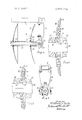
Referring to the drawings:
FIG. I is a fragmentary sectional elevation of a disc gang of an implement embodying the invention;
FIG. 2 is an enlarged fragment of FIG. 1;
FIG. 3 is a view similar to FIG. 2 showing a modification; and
FIG. 4 is an end view of the embodiment shown in FIG. 1.
Referring now to the drawings, and more particularly to FIGS. I and 2, the disc gang indicated in its entirety by the reference numeral 10 includes a frame 12 to which are fixed supporting standards 14 (only one of which is shown) by means of U-bolt 16. The lower ends of the standards carry bearings I8 (FIG. 4) which are joumaled in cylindrical bearing sleeves 20, the former having apertures 22 of hexagon cross section to receive a hexagon gang bolt 24. Disposed on the bolt 24 are concave-convex ground working discs 26, each of which is provided with a hexagon opening 28 adapted to receive the bolt 24. The opening 28 is only large enough to pennit axial sliding movement of the disc on the bolt. Between each pair of adjacent discs is disposed a spacing spool 30 having an interior passage 32 of hexagon cross section adapted to slide over the bolt 24 to prevent rotation of the spool relative to the bolt 24. Adjacent the right-hand end of frame 12 bearing spool 34 (FIG. I) is provided having an interior hexagon passageway 36 of a size to receive bolt 24.
A spring steel disc 40 is positioned between end face of spool 30 and a second larger spring steel disc 42 which is mounted to contact one side of disc 26. A spring steel disc 44 is positioned between the end of spacer spool 34 and the other side of disc 26. Disc 44 is identical "to disc 40, however, if desired; disc 40 may be dished to conform to the curvature of disc 26 and disc 44 may be flat as indicated in FIG. 3 but will resiliently conform to the shape of blade 26 when bolt 24 has been tightened. Blade 44 in FIG. 3 thus functions like a Belleville washer.
It should now be apparent that when bolt 24 is tightened in a conventional manner, spacer spools 30 and 34 will be drawn up against spring steel discs 40 and 44 which in turn clamp discs 42 and 26 therebetween.
Then if the disc 26 strikes a rock or stone when it is being drawn through a soil bed, disc 26 will deflect about the outer periphery of disc 42 and if the contact between rock andblade 26 is severe enough then the blade 26 will additionally deflect about the peripheral edge of blade 40 and if severe enough, about the outer edge of spacer spool 30, much in themanner of a leaf spring. And if the contact between rock and blade 26 is severe enough, standard members 14 will also flex to minimize damage to blade 26.
It is seen that standard 14 (FIG. 4) is tapered and is provided with a relatively large base portion for attachment to frame I2 and its opposite end is much smaller so that standard 14 is in the nature of a cantilever beam of uniform strength.
From the foregoing, it should now be apparent that means has been provided for minimizing damage to discs by providing a resilient mounting but which still maintains the disc in working attitude. That is, the mounting is such that the disc can bend'but it will not tilt relative to .the gang bolt to get out of good working position.
The embodiments of the invention in which an exclusive property or privilege is claimed are defined as follows:
Iclaim:
I. In a ground working tool, a gang bolt, a ground working disc havingan aperture through which saidbolt extends, a plurality of spring steel discs mounted on said bolt with at least one of said spring steel discs being mounted on each side of said ground working disc in contacting relation thereto, a pair of spacer spools mounted on said bolt outboard from said spring steel discs for comparing said spring steel discs and said ground working disc in rigid relation to said bolt, said spring steel discs having a greater diameter than said spools and a lesser diameter than said ground working disc, the spring steel discs positioned adjacent to said working disc being formed to contact said working disc from said bolt to the peripheral surface of said spring steel discs to provide a leaf spring support for said working disc, one of said discs contacting said ground working disc having a diameter greater than the other of said contacting discs, an additional spring steel disc mounted between one of said contacting discs and one of said spools, said additional disc being of a diameter less than the adjacent contacting disc and being of a conformation complementary to' said adjacent disc so as to contact same from said bolt to the periphery of said additional disc to provide an additional spring in the leaf spring mounting of said ground working disc.
2. In a ground working tool as recited in claim 1 and wherein said discs are concave-convex and said additional disc 4. In a ground working tool as recited in claim 3 and wherein said additional disc has a diameter less than the diameter of the spring steel disc mounted adjacent thereto.
5. In a ground working tool as recited in claim 4 and wherein the diameter of said additional steel disc is equal to the diameter of the spring steel disc mounted adjacent to the concave side of said ground wording disc.
POMS) UNITED STATES PA'IEN'E. OFFECE s v, CERTHICATL Oi CORHELLI, F
Patent No. 305760216 Dateh April Inventor(s) Willard H. Tanke It is certified that error appears in the abovc--tifi .113 .ierf p nnni and that said Letters Patent are hereby corrected as; nhmm 'bvlc w:
In the Abstract, line 8, after "and" and before "the" if should be inserted; Column 2, line 56, "compel should read clamping Column 3, line 4, after *2 and should be inserted; Column 4, line 7, "wording should read working Signed and sealed this hth day of January 1972.
(SEAL) Attest:
EDWARD M,FLETGH ER,JR ROBERT GOTTSCHALK Attesting Officer Acting Commissioner of Pa?

Claims (5)

1. In a ground working tool, a gang bolt, a ground working disc having an aperture through which said bolt extends, a plurality of spring steel discs mounted on said bolt with at least one of said spring steel discs being mounted on each side of said ground working disc in contacting relation thereto, a pair of spacer spools mounted on said bolt outboard from said spring steel discs for comparing said spring steel discs and said ground working disc in rigid relation to said bolt, said spring steel discs having a greater diameter than said spools and a lesser diameter than said ground working disc, the spring steel discs positioned adjacent to said working disc being formed to contact said working disc from said bolt to the peripheral surface of said spring steel discs to provide a leaf spring support for said working disc, one of said discs contacting said ground working disc having a diameter greater than the other of said contacting discs, an additional spring steel disc mounted between one of said contacting discs and one of said spools, said additional disc being of a diameter less than the adjacent contacting disc and being of a conformation complementary to said adjacent disc so as to contact same from said bolt to the periphery of said additional disc to provide an additional spring in the leaf spring mounting of said ground working disc.
2. In a ground working tool as recited in claim 1 and wherein said discs are concave-convex and said additional disc is mounted adjacent to the convex side of said one of said discs and being spaced from said ground working disc by said one of said discs.
3. In a ground working tool as recited in claim 2 wherein the spring steel disc positioned adjacent the concave side of said ground working disc is a flat disc and is deformed to assume a shape complementary to the concave side of said ground working disc by a tightening action of said bolt for moving said spools towards each other.
4. In a ground working tool as recited in claim 3 and wherein said additional disc has a diameter less than the diameter of the spring steel disc mounted adjacent thereto.
5. In a ground working tool as recited in claim 4 and wherein the diameter of said additional steel disc is equal to the diameter of the spring steel disc mounted adjacent to the concave side of said ground wording disc.
US809176A 1969-03-21 1969-03-21 Spring mounting for disc harrow blades Expired - Lifetime US3576216A (en)

Applications Claiming Priority (1)

Application Number Priority Date Filing Date Title
US80917669A 1969-03-21 1969-03-21

Publications (1)

Publication Number Publication Date
US3576216A true US3576216A (en) 1971-04-27

Family

ID=25200714

Family Applications (1)

Application Number Title Priority Date Filing Date
US809176A Expired - Lifetime US3576216A (en) 1969-03-21 1969-03-21 Spring mounting for disc harrow blades

Country Status (1)

Country Link
US (1) US3576216A (en)

Cited By (15)

* Cited by examiner, † Cited by third party
Publication number Priority date Publication date Assignee Title
US3669193A (en) * 1970-12-09 1972-06-13 Kewanee Mach & Conveyor Co Gang bolt locking arrangement
US3690385A (en) * 1969-09-09 1972-09-12 Stanley Marian Weiss Cultivating implements
US3773112A (en) * 1970-02-11 1973-11-20 E Zinck Motor operated hand hoe
US4066132A (en) * 1976-02-20 1978-01-03 Deere & Company Disk harrow with beam member suspended by u-shaped springs
US4275791A (en) * 1979-07-27 1981-06-30 Rottinghaus Robert B Yieldable disc blade assembly
FR2580139A1 (en) * 1985-04-11 1986-10-17 Fortschritt Veb K Set of discs for disc harrows
US4842077A (en) * 1988-06-20 1989-06-27 Deere & Company Disk harrow standard for support beams of different cross sections
US20070029100A1 (en) * 2005-08-08 2007-02-08 Tschetter Ronald R Disc bearing attachment for chisel plow
USD624938S1 (en) * 2007-06-19 2010-10-05 Kelly Shane P Concave disc
WO2015131246A1 (en) * 2014-03-03 2015-09-11 Hard Metals Australia Pty Limited Agricultural ground engaging chain
US20190174665A1 (en) * 2017-12-11 2019-06-13 Marchesan Implementos E Maquinas Agricolas Tatu S.A. Agricultural tilting bearing assembly and improved support bracket for connecting the same to agricultural equipment
USD880279S1 (en) 2017-12-11 2020-04-07 Marchesan Implementos E Maquinas Agricolas Tatu S.A. Support bracket
US20210059092A1 (en) * 2018-02-07 2021-03-04 Deere & Company Tillage machine and tillage disk for the same
US20230309430A1 (en) * 2020-09-04 2023-10-05 Iron Grip Holdings Pty Limited Agricultural ground engaging chain and link system
US12369516B2 (en) 2020-04-01 2025-07-29 Deere & Company Brush belt for seed delivery

Citations (7)

* Cited by examiner, † Cited by third party
Publication number Priority date Publication date Assignee Title
US1183828A (en) * 1914-06-04 1916-05-16 Einar Wilhelm Bjorkman Harrow.
GB261823A (en) * 1925-08-15 1926-11-15 William Charles Goulding Improvements in and relating to hoes
US2197424A (en) * 1939-01-19 1940-04-16 Int Harvester Co Tilling implement
DE806176C (en) * 1949-08-12 1951-06-11 Ludwig Tepper Additional device for the chopping machine
US2773343A (en) * 1952-10-10 1956-12-11 Oppel Heinz Carl Cooperating rotatable disk type beet harvester
GB776767A (en) * 1954-05-19 1957-06-12 Hargreaves & Company Ltd W Improvements in or relating to apparatus for the treatment of turf or for like purposes
FR1284428A (en) * 1960-03-26 1962-02-09 Lely Nv C Van Der Device for working a strip of land

Patent Citations (7)

* Cited by examiner, † Cited by third party
Publication number Priority date Publication date Assignee Title
US1183828A (en) * 1914-06-04 1916-05-16 Einar Wilhelm Bjorkman Harrow.
GB261823A (en) * 1925-08-15 1926-11-15 William Charles Goulding Improvements in and relating to hoes
US2197424A (en) * 1939-01-19 1940-04-16 Int Harvester Co Tilling implement
DE806176C (en) * 1949-08-12 1951-06-11 Ludwig Tepper Additional device for the chopping machine
US2773343A (en) * 1952-10-10 1956-12-11 Oppel Heinz Carl Cooperating rotatable disk type beet harvester
GB776767A (en) * 1954-05-19 1957-06-12 Hargreaves & Company Ltd W Improvements in or relating to apparatus for the treatment of turf or for like purposes
FR1284428A (en) * 1960-03-26 1962-02-09 Lely Nv C Van Der Device for working a strip of land

Cited By (25)

* Cited by examiner, † Cited by third party
Publication number Priority date Publication date Assignee Title
US3690385A (en) * 1969-09-09 1972-09-12 Stanley Marian Weiss Cultivating implements
US3773112A (en) * 1970-02-11 1973-11-20 E Zinck Motor operated hand hoe
US3669193A (en) * 1970-12-09 1972-06-13 Kewanee Mach & Conveyor Co Gang bolt locking arrangement
US4066132A (en) * 1976-02-20 1978-01-03 Deere & Company Disk harrow with beam member suspended by u-shaped springs
US4275791A (en) * 1979-07-27 1981-06-30 Rottinghaus Robert B Yieldable disc blade assembly
FR2580139A1 (en) * 1985-04-11 1986-10-17 Fortschritt Veb K Set of discs for disc harrows
US4842077A (en) * 1988-06-20 1989-06-27 Deere & Company Disk harrow standard for support beams of different cross sections
US20070029100A1 (en) * 2005-08-08 2007-02-08 Tschetter Ronald R Disc bearing attachment for chisel plow
USD624938S1 (en) * 2007-06-19 2010-10-05 Kelly Shane P Concave disc
RU2683728C2 (en) * 2014-03-03 2019-04-01 Хард Металс Острелиа Пти Лимитед Ground engaging chain of agricultural implement
US10405472B2 (en) 2014-03-03 2019-09-10 Hard Metals Australia Pty Limited Agricultural ground engaging chain
EP3113595A4 (en) * 2014-03-03 2018-02-21 Hard Metals Australia Pty Limited Agricultural ground engaging chain
WO2015131246A1 (en) * 2014-03-03 2015-09-11 Hard Metals Australia Pty Limited Agricultural ground engaging chain
CN106061237B (en) * 2014-03-03 2019-05-03 哈德麦托斯澳大利亚有限公司 Agricultural grounding chain
CN106061237A (en) * 2014-03-03 2016-10-26 哈德麦托斯澳大利亚有限公司 Agricultural ground engaging chain
US10512206B2 (en) * 2017-12-11 2019-12-24 Marchesan Implementos E Maquinas Agricolas Tatu S.A. Agricultural tilting bearing assembly and improved support bracket for connecting the same to agricultural equipment
US20190174665A1 (en) * 2017-12-11 2019-06-13 Marchesan Implementos E Maquinas Agricolas Tatu S.A. Agricultural tilting bearing assembly and improved support bracket for connecting the same to agricultural equipment
US10542659B2 (en) 2017-12-11 2020-01-28 Marchesan Implementos E Maquinas Agricolas Tatu S.A. Agricultural tilting bearing assembly and improved support bracket for connecting the same to agricultural equipment
USD880279S1 (en) 2017-12-11 2020-04-07 Marchesan Implementos E Maquinas Agricolas Tatu S.A. Support bracket
AU2018236861B2 (en) * 2017-12-11 2023-12-14 Marchesan Implementos E Máquinas Agrícolas Tatu S.A. Agricultural tilting bearing assembly and improved support bracket for connecting the same to agricultural equipment
AU2023274120B2 (en) * 2017-12-11 2025-02-20 Marchesan Implementos E Máquinas Agrícolas Tatu S.A. Agricultural tilting bearing assembly and improved support bracket for connecting the same to agricultural equipment
US20210059092A1 (en) * 2018-02-07 2021-03-04 Deere & Company Tillage machine and tillage disk for the same
US11882778B2 (en) * 2018-02-07 2024-01-30 Deere & Company Tillage machine and tillage disk for the same
US12369516B2 (en) 2020-04-01 2025-07-29 Deere & Company Brush belt for seed delivery
US20230309430A1 (en) * 2020-09-04 2023-10-05 Iron Grip Holdings Pty Limited Agricultural ground engaging chain and link system

Similar Documents

Publication Publication Date Title
US3576216A (en) Spring mounting for disc harrow blades
US3794121A (en) Soil aerator
CA1181979A (en) Pivotal disc gang section
EP0170140B1 (en) Scraper for the disc blade of a seed drill
US4858699A (en) Scraper device for an agricultural implement
US20190126283A1 (en) Rotary reducing component
US10531602B2 (en) Implements for displacing ground material
BRPI0708052A2 (en) rotary agricultural tool with bearing arrangement
CA2466719C (en) Single standard double disk configuration
US2908338A (en) Fluted coulter disc
US2430434A (en) Clamping device for tool standards
US2659291A (en) Reversible disk attachment for agricultural implements
CN219660355U (en) Spacing adjusting mechanism for spacing sleeve of seed groove compression roller
US2693748A (en) Tractor mounted bedder
DK3014966T3 (en) Plate holder and scraper assembly for disc harrows
CH666830A5 (en) Grinder.
US4235294A (en) Soil cultivating machine
US3150721A (en) Resilient mounting means for a rotating tool
US3005501A (en) Disks and disk implements
GB1564492A (en) Mowing machines
US3442336A (en) Flexible mounting for disk harrow gang
US5040617A (en) Active harrow
EP3090612B1 (en) Ground processing disc
US3672453A (en) Machine for digging soil
US1092632A (en) Plow.

Legal Events

Date Code Title Description
AS Assignment

Owner name: WOODS KATHLEEN D., AS TRUSTEE

Free format text: SECURITY INTEREST;ASSIGNOR:ALLIS-CHALMERS CORPORATION A DE CORP.;REEL/FRAME:004149/0001

Effective date: 19830329

Owner name: CONNECTICUT NATIONAL BANK THE, A NATIONAL BANKING

Free format text: SECURITY INTEREST;ASSIGNOR:ALLIS-CHALMERS CORPORATION A DE CORP.;REEL/FRAME:004149/0001

Effective date: 19830329

AS Assignment

Owner name: DEUTZ-ALLIS CORPORATION BOX 933, MILWAUKEE, WI 53

Free format text: ASSIGNMENT OF ASSIGNORS INTEREST.;ASSIGNOR:ALLIS-CHALMER CORPORATION A DE CORP;REEL/FRAME:004434/0722

Effective date: 19850627