EP0041163A2 - Dispositif de sécurité commandé thermiquement pour chaudière de chauffage dans des installations de chauffage à circuit hydraulique fermé - Google Patents
Dispositif de sécurité commandé thermiquement pour chaudière de chauffage dans des installations de chauffage à circuit hydraulique fermé Download PDFInfo
- Publication number
- EP0041163A2 EP0041163A2 EP81103711A EP81103711A EP0041163A2 EP 0041163 A2 EP0041163 A2 EP 0041163A2 EP 81103711 A EP81103711 A EP 81103711A EP 81103711 A EP81103711 A EP 81103711A EP 0041163 A2 EP0041163 A2 EP 0041163A2
- Authority
- EP
- European Patent Office
- Prior art keywords
- valve
- safety device
- connection
- outlet
- temperature
- Prior art date
- Legal status (The legal status is an assumption and is not a legal conclusion. Google has not performed a legal analysis and makes no representation as to the accuracy of the status listed.)
- Granted
Links
- 238000010438 heat treatment Methods 0.000 title claims abstract description 47
- 239000003638 chemical reducing agent Substances 0.000 claims abstract description 23
- 239000008236 heating water Substances 0.000 claims abstract description 18
- 239000013505 freshwater Substances 0.000 claims abstract description 12
- 239000004449 solid propellant Substances 0.000 claims abstract description 7
- 238000009434 installation Methods 0.000 abstract 5
- XLYOFNOQVPJJNP-UHFFFAOYSA-N water Substances O XLYOFNOQVPJJNP-UHFFFAOYSA-N 0.000 description 20
- 230000006835 compression Effects 0.000 description 2
- 238000007906 compression Methods 0.000 description 2
- 239000012528 membrane Substances 0.000 description 2
- 238000000034 method Methods 0.000 description 2
- 238000005192 partition Methods 0.000 description 2
- 238000000926 separation method Methods 0.000 description 2
- 238000007664 blowing Methods 0.000 description 1
- 230000001276 controlling effect Effects 0.000 description 1
- 230000001419 dependent effect Effects 0.000 description 1
- 238000010586 diagram Methods 0.000 description 1
- 239000000284 extract Substances 0.000 description 1
- 238000004519 manufacturing process Methods 0.000 description 1
- 230000001105 regulatory effect Effects 0.000 description 1
- 238000007789 sealing Methods 0.000 description 1
- 238000011144 upstream manufacturing Methods 0.000 description 1
Images

Classifications
-
- F—MECHANICAL ENGINEERING; LIGHTING; HEATING; WEAPONS; BLASTING
- F24—HEATING; RANGES; VENTILATING
- F24D—DOMESTIC- OR SPACE-HEATING SYSTEMS, e.g. CENTRAL HEATING SYSTEMS; DOMESTIC HOT-WATER SUPPLY SYSTEMS; ELEMENTS OR COMPONENTS THEREFOR
- F24D19/00—Details
- F24D19/10—Arrangement or mounting of control or safety devices
- F24D19/1006—Arrangement or mounting of control or safety devices for water heating systems
- F24D19/1009—Arrangement or mounting of control or safety devices for water heating systems for central heating
-
- F—MECHANICAL ENGINEERING; LIGHTING; HEATING; WEAPONS; BLASTING
- F24—HEATING; RANGES; VENTILATING
- F24H—FLUID HEATERS, e.g. WATER OR AIR HEATERS, HAVING HEAT-GENERATING MEANS, e.g. HEAT PUMPS, IN GENERAL
- F24H9/00—Details
- F24H9/20—Arrangement or mounting of control or safety devices
- F24H9/2007—Arrangement or mounting of control or safety devices for water heaters
- F24H9/2057—Arrangement or mounting of control or safety devices for water heaters using solid fuel
Definitions
- the invention relates to a thermally controlled safety device for boilers heated with solid fuels in closed heating systems, in which, in the event of an excess temperature in the heating system, cold fresh water from the supply line is let into the system of the heating system and hot heating water is drained into a drain, comprising: one to the system of the heating system led fresh water supply line, in which a pressure reducer, a temperature-controlled valve and a pipe separator are arranged and a drain line connected to the system of the heating system, in which a thermal safety device is arranged, the thermal safety device of the same from the heating water temperature acted upon temperature sensor is controlled like the temperature-controlled valve and opens at a slightly higher temperature than this valve.
- Heating systems are usually designed as closed heating systems. A higher than atmospheric pressure can arise in the heating system. Pressure fluctuations are absorbed by a pressure compensation vessel. Such closed heating systems must contain a safety valve so that heating water is blown off in the event of an excessive pressure in the system and in the boiler. Such a blow-off at overpressure takes place when the boiler heats the heating water too much. Blowing off heating water in closed systems is very annoying, since the desired overpressure can then no longer be maintained at normal heating water temperature.
- the heat supply and thus the temperature of the heating water can be conveniently regulated so that excess temperatures and overpressure, which would lead to the safety valve responding, hardly occur.
- the heating system on the one hand as a closed heating system in heating systems in which the boiler is heated with solid fuels and is accordingly less easy to regulate, and on the other hand to prevent the safety valve from responding undesirably frequently, it is known to have one in the hot water side Boiler built-in Water heater or a heat exchanger specially installed as a safety device to use a thermally controlled valve. If the temperature of the heating water exceeds a critical value, this thermally controlled valve opens. Cold fresh water flows from the supply line through the water heater or heat exchanger, extracts heat from the heating water and flows out to a drain as warm water. This thermally controlled valve is referred to as a "thermal safety valve". This thermal process safety device removes heat from the boiler and thus cools down the temperature of the heating water to an uncritical value.
- This process requires a boiler with a water heater or a special heat exchanger. However, it is not possible to secure a boiler in this way without a water heater or separate heat exchanger. However, precisely this task often arises when a boiler previously operated with oil or gas is to be converted to solid fuels.
- An arrangement is known which, even with such boilers, ensures that the closed heating system is protected against overtemperature and thus overpressure.
- two thermal discharge safeguards controlled by a common temperature sensor are provided, which open at slightly different temperatures.
- a supply line is connected to the return of the heating system via the first thermal discharge safety device that opens at the lower temperature.
- the second thermal discharge safety device that opens at the higher temperature connects the flow of the boiler with an outlet.
- the first thermal discharge safety device is connected to the return via a pipe separator.
- a conventional pressure limiter is connected upstream of the first thermal discharge safety device.
- the first thermal safety device is opened first. This gives the outlet pressure of the pressure limiter to the pipe separator, which then establishes the connection to the heating system. Since the system is closed, no water flows into the system at first. At a slightly higher temperature, however, the second thermal safety device is opened so that warm water flows out of the boiler flow and cold water can flow into the system from the supply line. When the boiler has cooled down to an uncritical temperature, the two thermal discharge safety devices close one after the other, the pipe separator again mechanically separates the supply line from the heating system.
- thermal discharge safeguards are provided, which control the cold water inflow and hot water outflow.
- thermal drain safeguards are valves with a relatively large cross section, since the entire cold water inflow or hot water outflow must pass through these thermal drain safeguards.
- the pipe separator is connected in series with the first thermal drain safety device. The cold fresh water flowing through the pipe separator during the production of the flow connection thus flows first through the first thermal discharge safety device and then through the through flow channel of the pipe separator.
- the object of the invention is to design a thermally controlled safety device of the type defined at the outset in a simpler and more space-saving manner.
- the flow connection of the tube separator via which the entire fresh water flow is to flow, is thus directly connected to the outlet of the pressure reducer.
- the entire fresh water flow does not need to flow through this poppet valve, but only the amount of water that moves the pipe separator into its working position. It becomes a thermal safety device saved.
- the arrangement becomes simpler and more compact.
- 10 denotes a boiler heated with solid fuels. From the boiler 10 there is a supply 12 of a closed heating system, the return 14 is returned to the boiler 10.
- the closed heating system contains an expansion vessel 16 which compensates for the normal thermal expansion of the water in the closed heating system.
- a safety valve 18 is provided on the boiler 10.
- the 20 designates a supply line via which cold fresh water can be supplied.
- the pressure of the supply line 20 is reduced via a pressure reducer 22 to a pressure which is conducive to the boiler 10 ' and the heating system and which is below the response pressure of the safety valve 18.
- a pipe separator 24 between the pressure reducer 22 and the heating system is a pipe separator 24 in series with a backflow preventer 26, which is between the outlet port 28 of the pipe separator 24 and the heater plant lies.
- the pipe separator has a flow connection 30 of large cross section and a control connection 32 of small cross section.
- the flow connection 30 is connected directly to the outlet of the pressure reducer 22.
- the control connection 32 which is also connected to the outlet of the pressure reducer, is controlled by a thermally controlled poppet valve 34.
- a temperature sensor 36 controls a thermal discharge safety device 38 by means of an actuator 40.
- the thermal discharge safety device 38 is a thermally controlled valve which connects a line 42 connected to the system of the heating system to an outlet 44.
- the poppet valve 34 is controlled 38 controlling valve stem 46 from the Lan by the actuator 40 of the temperature sensor 36 g sverschieb- cash, at the same time the valve disc of the thermal safety.
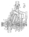
- the pressure reducer 22 has a housing 46, in which a membrane 48 is clamped, which is loaded by a spring 50.
- the space below the membrane is divided by a partition 52 into a chamber 54 and an inlet chamber 56.
- a valve tappet 58 of a pressure reducing valve 60 which cooperates with a valve seat 62 formed at the lower end of the housing 46, is sealingly guided through the partition wall 52.
- a cross bore 64 running in the valve tappet 58 connects the outlet 66 of the pressure reducer downstream of the valve 60 to the chamber 54.
- the chamber 56 is connected to the supply line 20 (FIG. 1) via a connection 68.
- the pipe separator 24 has a cylindrical housing 70, on which the inlet-side flow connection 30 and an outlet connection 28 are provided on opposite sides. In its lower end part, the housing 70 has an outlet 76. In the flow connection 30 there is an inlet sleeve 78 which is closed at the end at its end facing away from the flow connection 30 and has lateral outlet openings 80. On the inlet sleeve 78, an annular piston 82 guided in the housing 70 is slidably movable with a sleeve-shaped shaft 84 sealingly enclosing the inlet sleeve 78. The control connection 32 opens into the annular space 86 between the housing 70 and the annular piston 82.
- the outlet connection 28 is surrounded by a connecting piece 90 which projects into the housing 70 and is provided with an inner seal 88.
- the sleeve-shaped shaft 84 of the annular piston 82 can be inserted in a sealing manner during a working stroke thereof.
- the shaft 84 has an undercut 92 on its inner wall, via which, after the shaft 84 has been inserted into the socket 90, a connection is established between the lateral outlet openings 80 of the inlet sleeve 78 and the bore of the shaft 84 connected to the outlet connection 28.
- the annular piston is loaded by a compression spring 94 so that it is in the rest position shown in FIG. 2 in the absence of a control pressure at the control connection 32.
- the actuator 40 and the valve tappet 46 are controlled by the sensor 36.
- the thermal leakage protection contains a housing 96 with a connection 98 which is connected to the line 42 (FIG. 1) and a connection 100 which is connected to the outlet 44.
- a valve seat 1 0 2 is formed, on which a valve plate 104 is seated.
- the valve plate 104 is loaded by a spring 106. It has a collar 108 which is sealingly guided in the housing 96.
- the housing 96 has a neck 110 coaxial with the collar 108, into which spring 106, which is supported on an annular spring abutment 112, projects.
- a chamber 114 is thus formed in the socket 110 and is sealed off from the inlet-side connection 98 by the collar 108 and its guide in the housing 96.
- the actuator 40 with the valve tappet 46 sits on the housing 96 coaxially with the valve seat 102 and the valve plate 104.
- the valve tappet 46 is sealingly guided through the valve plate 104. It has a shoulder 116 which, after a certain stroke of the valve tappet 46, engages the valve plate 104 and presses the valve against the action of the spring 106.
- the housing 46 of the pressure reducer 22 is connected to the socket 110.
- the housing 46 forms a valve seat 116 coaxial with the valve seat 62.
- the valve tappet 46 extends through the valve seat 116 and carries at its end the valve disk 118 of the temperature-controlled poppet valve 32 (FIG. 1).
- a valve plate 120 is furthermore attached to the valve tappet 46, which cooperates with a valve seat 122 and, after a stroke of the valve tappet 46 that opens the valve 32, closes off the passage 124 formed along the valve tappet 46.
- This passage 124 communicates with the outlet 100 of the thermal discharge safety device via the chamber 114 and a bore 126 formed in the valve tappet 46.
- the valve tappet 46 consists of two sections 46a and 46b which are displaceably guided to one another.
- a preloaded spring 128 is arranged between the sections 46a and 46b.
- One section 46a bears under the action of the spring 128 against a stop 129 of the other section 46b. If the poppet valve 32 is open and the valve disk 120 bears against the valve seat 122, the actuator 40 can possibly push the valve tappet 46 further upward in FIG. 2. Since the valve plate 120 abuts the valve seat 122 and thus limits the upward movement of the upper section 46b of the valve tappet 46, the additional movement of the lower section 46a of the valve tappet is absorbed by compressing the spring 128. In normal operation, the two sections 46a and 46b act like a rigid connection, since the pretension of the spring 128 is normally not exceeded.
- the upper section 46b contains, next to the valve plate 120, a cup-shaped part 130, in which a head piece 132 of the lower section 46a is guided.
- the spring 128 sits between the bottom of the pot-shaped part 130 and the head piece 132.
- the pot-shaped part 130 forms a shoulder 134, against which a compression spring 136, which is supported on the housing 46, bears.
- the valve lifter 46 is preloaded in such a way that the valve disc 118 is normally seated on the valve seat 116 and the poppet valve 32 is closed.
- the poppet valve 32 is pressed against the action of the spring 136 by the actuator 40 via the valve tappet 46.
- the control connection 32 of the pipe separator 24 branches off between the poppet valves 34 and 120, 122.
- the pressure reducer 22 is arranged with its pressure reducer valve 60 coaxially with the valve lifter 46 and the poppet valves 34 and 120, 122, respectively. In the fully open state, the pressure reducing valve 60 closes the poppet valve 34 which controls the control connection 32 and the second poppet valve 120, 122.
- the shoulder 116 rests on the valve plate 104 and opens the thermal discharge safety device 38. Warm water from the heating system can now flow through the Drain the thermal safety device 38 into the drain 44. So cold fresh water is let into the heating system while warm heating water flows off. This will cool down the heating system.
- the valve 34 closes.
- the valve disk 120 lifts off from the valve seat 122.
- the annular chamber 86 is connected to the outlet 100 of the thermal discharge safety device 38 via the passage 124. The water from the annular chamber 86 can thus flow away, and the piston 82 with the shaft 84 returns to the starting position shown under the influence of the spring 94.
- the arrangement described has another advantage. If the pressure in the supply line should collapse, then this means that the pressure reducer 122 opens fully under the influence of the spring 50, that is to say the pressure reducing valve 60 is moved downward enough to close the poppet valve 34 while overcoming the spring 128. At the same time, the valve plate 120 lifts off the valve seat 122, so that in this case the pipe separator 24 also returns to the rest position shown. When the pressure in the supply line collapses, a safe separation of the heating system and supply line is guaranteed.
Landscapes
- Engineering & Computer Science (AREA)
- Physics & Mathematics (AREA)
- Thermal Sciences (AREA)
- Chemical & Material Sciences (AREA)
- Combustion & Propulsion (AREA)
- Mechanical Engineering (AREA)
- General Engineering & Computer Science (AREA)
- Electric Stoves And Ranges (AREA)
- Frying-Pans Or Fryers (AREA)
- Temperature-Responsive Valves (AREA)
- Regulation And Control Of Combustion (AREA)
- Feeding And Controlling Fuel (AREA)
- Instantaneous Water Boilers, Portable Hot-Water Supply Apparatuses, And Control Of Portable Hot-Water Supply Apparatuses (AREA)
- Air-Conditioning For Vehicles (AREA)
- Control Of Resistance Heating (AREA)
- Resistance Heating (AREA)
Priority Applications (1)
| Application Number | Priority Date | Filing Date | Title |
|---|---|---|---|
| AT81103711T ATE8814T1 (de) | 1980-05-31 | 1981-05-14 | Thermisch gesteuerte sicherheitseinrichtung fuer kessel in geschlossenen heizungsanlagen. |
Applications Claiming Priority (2)
| Application Number | Priority Date | Filing Date | Title |
|---|---|---|---|
| DE3020797 | 1980-05-31 | ||
| DE19803020797 DE3020797A1 (de) | 1980-05-31 | 1980-05-31 | Thermisch gesteuerte sicherheitseinrichtung fuer kessel in geschlossenen heizungsanlagen |
Publications (3)
| Publication Number | Publication Date |
|---|---|
| EP0041163A2 true EP0041163A2 (fr) | 1981-12-09 |
| EP0041163A3 EP0041163A3 (en) | 1982-01-20 |
| EP0041163B1 EP0041163B1 (fr) | 1984-08-01 |
Family
ID=6103720
Family Applications (1)
| Application Number | Title | Priority Date | Filing Date |
|---|---|---|---|
| EP81103711A Expired EP0041163B1 (fr) | 1980-05-31 | 1981-05-14 | Dispositif de sécurité commandé thermiquement pour chaudière de chauffage dans des installations de chauffage à circuit hydraulique fermé |
Country Status (5)
| Country | Link |
|---|---|
| EP (1) | EP0041163B1 (fr) |
| AT (1) | ATE8814T1 (fr) |
| DE (2) | DE3020797A1 (fr) |
| DK (1) | DK228881A (fr) |
| NO (1) | NO151384C (fr) |
Cited By (2)
| Publication number | Priority date | Publication date | Assignee | Title |
|---|---|---|---|---|
| EP0179271A2 (fr) * | 1984-09-25 | 1986-04-30 | Hans Sasserath & Co Kg | Dispositif d'alimentation pour le remplissage d'installations de chauffage fermées |
| GB2488395A (en) * | 2011-02-22 | 2012-08-29 | Sasserath & Co Kg H | Assembly for controlling the temperature of a drinking water heater |
Citations (3)
| Publication number | Priority date | Publication date | Assignee | Title |
|---|---|---|---|---|
| DE6927453U (de) * | 1969-07-10 | 1969-10-30 | Guenter Verleger | Vorrichtung fuer warmwasser-zentralheizungen. |
| DE1600977B2 (de) * | 1967-06-08 | 1973-10-11 | Davy-Ashmore Ag, 6000 Frankfurt | Beheizbare Ventilbattene |
| DE2713155A1 (de) * | 1977-03-25 | 1978-10-05 | Krupp Gmbh | Temperaturgesteuerte vorrichtung im kreislauf einer heizanlage, die das aufheizen des kessels ueber eine oberste grenztemperatur verhindert |
Family Cites Families (1)
| Publication number | Priority date | Publication date | Assignee | Title |
|---|---|---|---|---|
| DE7401779U (de) * | 1974-09-12 | Stadler J Kg | Vorrichtung zur thermischen Absicherung für Heizkessel mit oder ohne temperaturgesteuertem Brauchwassererwärmer in geschlossenen Wasserheizungsanlagen |
-
1980
- 1980-05-31 DE DE19803020797 patent/DE3020797A1/de not_active Withdrawn
-
1981
- 1981-05-14 EP EP81103711A patent/EP0041163B1/fr not_active Expired
- 1981-05-14 AT AT81103711T patent/ATE8814T1/de not_active IP Right Cessation
- 1981-05-14 DE DE8181103711T patent/DE3165205D1/de not_active Expired
- 1981-05-26 DK DK228881A patent/DK228881A/da not_active Application Discontinuation
- 1981-05-29 NO NO811815A patent/NO151384C/no unknown
Patent Citations (3)
| Publication number | Priority date | Publication date | Assignee | Title |
|---|---|---|---|---|
| DE1600977B2 (de) * | 1967-06-08 | 1973-10-11 | Davy-Ashmore Ag, 6000 Frankfurt | Beheizbare Ventilbattene |
| DE6927453U (de) * | 1969-07-10 | 1969-10-30 | Guenter Verleger | Vorrichtung fuer warmwasser-zentralheizungen. |
| DE2713155A1 (de) * | 1977-03-25 | 1978-10-05 | Krupp Gmbh | Temperaturgesteuerte vorrichtung im kreislauf einer heizanlage, die das aufheizen des kessels ueber eine oberste grenztemperatur verhindert |
Cited By (4)
| Publication number | Priority date | Publication date | Assignee | Title |
|---|---|---|---|---|
| EP0179271A2 (fr) * | 1984-09-25 | 1986-04-30 | Hans Sasserath & Co Kg | Dispositif d'alimentation pour le remplissage d'installations de chauffage fermées |
| EP0179271A3 (en) * | 1984-09-25 | 1988-01-07 | Hans Sasserath & Co Kg | Filling arrangement for filling closed liquid heating circuits |
| GB2488395A (en) * | 2011-02-22 | 2012-08-29 | Sasserath & Co Kg H | Assembly for controlling the temperature of a drinking water heater |
| GB2488395B (en) * | 2011-02-22 | 2015-11-11 | Sasserath & Co Kg H | Assembly for controlling the temperature of a drinking water heater |
Also Published As
| Publication number | Publication date |
|---|---|
| NO811815L (no) | 1981-12-01 |
| ATE8814T1 (de) | 1984-08-15 |
| DK228881A (da) | 1981-12-01 |
| EP0041163B1 (fr) | 1984-08-01 |
| EP0041163A3 (en) | 1982-01-20 |
| NO151384C (no) | 1985-03-27 |
| NO151384B (no) | 1984-12-17 |
| DE3020797A1 (de) | 1981-12-17 |
| DE3165205D1 (en) | 1984-09-06 |
Similar Documents
| Publication | Publication Date | Title |
|---|---|---|
| DE10256035B3 (de) | Wärmetauscher-Ventilanordnung, insbesondere Heizkörper-Ventilanordnung | |
| EP0189565B1 (fr) | Régulateur d'eau de refroidissement pour moteurs à combustion | |
| DE2215150A1 (de) | Thermostatisches Expansionsventil | |
| DE2917233C2 (fr) | ||
| DE3344704C2 (de) | Absperrarmatur für Gasleitungen | |
| DE102006026001A1 (de) | Sicherheitseinrichtung für Wasserheizsystem | |
| EP0041163B1 (fr) | Dispositif de sécurité commandé thermiquement pour chaudière de chauffage dans des installations de chauffage à circuit hydraulique fermé | |
| EP0179271B1 (fr) | Dispositif d'alimentation pour le remplissage d'installations de chauffage fermées | |
| DE3632655C2 (fr) | ||
| DE2130601C3 (de) | Gasdruckregler | |
| EP0055813A1 (fr) | Soupape de sûreté contrôlée thermiquement | |
| DE1148411B (de) | Vorrichtung zum Regeln des Kuehlwasser-kreislaufes von Brennkraftmaschinen | |
| CH682510A5 (de) | Elektrisch betätigtes Ventil. | |
| DE19856009A1 (de) | Rücklauf-Raumtemperatur Regelventil mit Thermofühler | |
| DE10050207C1 (de) | Kombiventil für Heizungsanlagen | |
| DE628621C (de) | Einrichtung zur selbsttaetigen Regelung der Gaszufuhr zu einem Erhitzer | |
| EP1193434B1 (fr) | Soupape, en particulier soupape de radiateur | |
| DE2659456A1 (de) | Gasbeheizter durchlauf-wassererhitzer | |
| DE914697C (de) | Vorrichtung zur Druckminderung und UEberdrucksicherung | |
| DE3440588A1 (de) | Temperaturregler fuer waermetauscher | |
| DE1296436B (de) | Hydraulischer Stellmotor fuer Regelanlagen | |
| DE2104628A1 (de) | Thermostatgesteuertes Regelventil mit einer Einrichtung zum Auswechseln des Thermostaten oder sonstiger innerer Einbauteile aus dem Ventilgehäuse | |
| DE2713155A1 (de) | Temperaturgesteuerte vorrichtung im kreislauf einer heizanlage, die das aufheizen des kessels ueber eine oberste grenztemperatur verhindert | |
| DE3339518A1 (de) | Gasbeheizte waermequelle | |
| DE2149182B1 (de) | Thermisch steuerbares Ablaufventil |
Legal Events
| Date | Code | Title | Description |
|---|---|---|---|
| PUAI | Public reference made under article 153(3) epc to a published international application that has entered the european phase |
Free format text: ORIGINAL CODE: 0009012 |
|
| PUAL | Search report despatched |
Free format text: ORIGINAL CODE: 0009013 |
|
| AK | Designated contracting states |
Designated state(s): AT CH DE FR SE |
|
| 17P | Request for examination filed |
Effective date: 19811027 |
|
| AK | Designated contracting states |
Designated state(s): AT CH DE FR SE |
|
| GRAA | (expected) grant |
Free format text: ORIGINAL CODE: 0009210 |
|
| AK | Designated contracting states |
Designated state(s): AT CH DE FR LI SE |
|
| REF | Corresponds to: |
Ref document number: 8814 Country of ref document: AT Date of ref document: 19840815 Kind code of ref document: T |
|
| REF | Corresponds to: |
Ref document number: 3165205 Country of ref document: DE Date of ref document: 19840906 |
|
| ET | Fr: translation filed | ||
| PLBE | No opposition filed within time limit |
Free format text: ORIGINAL CODE: 0009261 |
|
| STAA | Information on the status of an ep patent application or granted ep patent |
Free format text: STATUS: NO OPPOSITION FILED WITHIN TIME LIMIT |
|
| 26N | No opposition filed | ||
| PGFP | Annual fee paid to national office [announced via postgrant information from national office to epo] |
Ref country code: AT Payment date: 19860514 Year of fee payment: 6 |
|
| PG25 | Lapsed in a contracting state [announced via postgrant information from national office to epo] |
Ref country code: AT Effective date: 19870514 |
|
| PG25 | Lapsed in a contracting state [announced via postgrant information from national office to epo] |
Ref country code: SE Effective date: 19870515 |
|
| PG25 | Lapsed in a contracting state [announced via postgrant information from national office to epo] |
Ref country code: LI Effective date: 19870531 Ref country code: CH Effective date: 19870531 |
|
| PG25 | Lapsed in a contracting state [announced via postgrant information from national office to epo] |
Ref country code: FR Free format text: LAPSE BECAUSE OF NON-PAYMENT OF DUE FEES Effective date: 19880129 |
|
| REG | Reference to a national code |
Ref country code: CH Ref legal event code: PL |
|
| PG25 | Lapsed in a contracting state [announced via postgrant information from national office to epo] |
Ref country code: DE Effective date: 19880202 |
|
| REG | Reference to a national code |
Ref country code: FR Ref legal event code: ST |
|
| EUG | Se: european patent has lapsed |
Ref document number: 81103711.8 Effective date: 19880601 |