EP0041163A2 - Thermally operated safety device for boilers in closed-circuit heating plants - Google Patents
Thermally operated safety device for boilers in closed-circuit heating plants Download PDFInfo
- Publication number
- EP0041163A2 EP0041163A2 EP81103711A EP81103711A EP0041163A2 EP 0041163 A2 EP0041163 A2 EP 0041163A2 EP 81103711 A EP81103711 A EP 81103711A EP 81103711 A EP81103711 A EP 81103711A EP 0041163 A2 EP0041163 A2 EP 0041163A2
- Authority
- EP
- European Patent Office
- Prior art keywords
- valve
- safety device
- connection
- outlet
- temperature
- Prior art date
- Legal status (The legal status is an assumption and is not a legal conclusion. Google has not performed a legal analysis and makes no representation as to the accuracy of the status listed.)
- Granted
Links
- 238000010438 heat treatment Methods 0.000 title claims abstract description 47
- 239000003638 chemical reducing agent Substances 0.000 claims abstract description 23
- 239000008236 heating water Substances 0.000 claims abstract description 18
- 239000013505 freshwater Substances 0.000 claims abstract description 12
- 239000004449 solid propellant Substances 0.000 claims abstract description 7
- 238000009434 installation Methods 0.000 abstract 5
- XLYOFNOQVPJJNP-UHFFFAOYSA-N water Substances O XLYOFNOQVPJJNP-UHFFFAOYSA-N 0.000 description 20
- 230000006835 compression Effects 0.000 description 2
- 238000007906 compression Methods 0.000 description 2
- 239000012528 membrane Substances 0.000 description 2
- 238000000034 method Methods 0.000 description 2
- 238000005192 partition Methods 0.000 description 2
- 238000000926 separation method Methods 0.000 description 2
- 238000007664 blowing Methods 0.000 description 1
- 230000001276 controlling effect Effects 0.000 description 1
- 230000001419 dependent effect Effects 0.000 description 1
- 238000010586 diagram Methods 0.000 description 1
- 239000000284 extract Substances 0.000 description 1
- 238000004519 manufacturing process Methods 0.000 description 1
- 230000001105 regulatory effect Effects 0.000 description 1
- 238000007789 sealing Methods 0.000 description 1
- 238000011144 upstream manufacturing Methods 0.000 description 1
Images

Classifications
-
- F—MECHANICAL ENGINEERING; LIGHTING; HEATING; WEAPONS; BLASTING
- F24—HEATING; RANGES; VENTILATING
- F24D—DOMESTIC- OR SPACE-HEATING SYSTEMS, e.g. CENTRAL HEATING SYSTEMS; DOMESTIC HOT-WATER SUPPLY SYSTEMS; ELEMENTS OR COMPONENTS THEREFOR
- F24D19/00—Details
- F24D19/10—Arrangement or mounting of control or safety devices
- F24D19/1006—Arrangement or mounting of control or safety devices for water heating systems
- F24D19/1009—Arrangement or mounting of control or safety devices for water heating systems for central heating
-
- F—MECHANICAL ENGINEERING; LIGHTING; HEATING; WEAPONS; BLASTING
- F24—HEATING; RANGES; VENTILATING
- F24H—FLUID HEATERS, e.g. WATER OR AIR HEATERS, HAVING HEAT-GENERATING MEANS, e.g. HEAT PUMPS, IN GENERAL
- F24H9/00—Details
- F24H9/20—Arrangement or mounting of control or safety devices
- F24H9/2007—Arrangement or mounting of control or safety devices for water heaters
- F24H9/2057—Arrangement or mounting of control or safety devices for water heaters using solid fuel
Abstract
Description
Die Erfindung betrifft eine thermisch gesteuerte Sicherheitseinrichtung für mit festen Brennstoffen beheizte Kessel in geschlossenen Heizungsanlagen, bei welcher im Fall einer Übertemperatur in der Heizungsanlage kaltes Frischwasser aus der Versorgungsleitung in das System der Heizungsanlage eingelassen und heißes Heizungswasser in einen Ablauf abgelassen wird, enthaltend: eine zu dem System der Heizungsanlage geführte Frischwasserzuleitung, in welcher in Reihe ein Druckminderer, ein temperaturgesteuertes Ventil und ein Rohrtrenner angeordnet sind und eine mit dem System der Heizungsanlage verbundene Ablaufleitung, in welcher eine thermische Ablaufsicherung angeordnet ist, wobei die thermische Ablaufsicherung von dem gleichen von der Heizungswassertemperatur beaufschlagten Temperaturfühler gesteuert ist wie das temperaturgesteuerte Ventil und bei einer geringfügig höheren Temperatur öffnet als dieses Ventil.The invention relates to a thermally controlled safety device for boilers heated with solid fuels in closed heating systems, in which, in the event of an excess temperature in the heating system, cold fresh water from the supply line is let into the system of the heating system and hot heating water is drained into a drain, comprising: one to the system of the heating system led fresh water supply line, in which a pressure reducer, a temperature-controlled valve and a pipe separator are arranged and a drain line connected to the system of the heating system, in which a thermal safety device is arranged, the thermal safety device of the same from the heating water temperature acted upon temperature sensor is controlled like the temperature-controlled valve and opens at a slightly higher temperature than this valve.
Heizungsanlagen werden üblicherweise als geschlossene Heizungsanlagen ausgebildet. In dem System der Heizungsanlage kann dabei ein höherer als atmosphärischer Druck entstehen. Druckschwankungen werden durch ein Druckausgleichsgefäß aufgenommen. Solche geschlossenen Heizungsanlagen müssen ein Sicherheitsventil enthalten, so daß bei Auftreten eines unzulässigen Überdrucks im System und im Kessel Heizungswasser abgeblasen wird. Ein solches Abblasen bei Überdruck findet statt, wenn der Kessel das Heizungswasser zu stark erhitzt. Das Abblasen von Heizungswasser bei geschlossenen Anlagen ist sehr störend, da dann bei normaler Heizungswassertemperatur der gewünschte Überdruck nicht mehr aufrechterhalten bleibt.Heating systems are usually designed as closed heating systems. A higher than atmospheric pressure can arise in the heating system. Pressure fluctuations are absorbed by a pressure compensation vessel. Such closed heating systems must contain a safety valve so that heating water is blown off in the event of an excessive pressure in the system and in the boiler. Such a blow-off at overpressure takes place when the boiler heats the heating water too much. Blowing off heating water in closed systems is very annoying, since the desired overpressure can then no longer be maintained at normal heating water temperature.
Bei Heizungsanlagen, bei denen der Kessel mit Öl oder Gas befeuert wird, läßt sich die Wärmezufuhr und damit die Temperatur des Heizungswassers bequem regeln, so daß Ubertemperaturen und Überdruck, die zu einem Ansprechen des Sicherheitsventils führen würden, kaum auftreten.In heating systems in which the boiler is fired with oil or gas, the heat supply and thus the temperature of the heating water can be conveniently regulated so that excess temperatures and overpressure, which would lead to the safety valve responding, hardly occur.
Das ist wesentlich schwieriger bei Heizungsanlagen, bei denen der Kessel mit festen Brennstoffen beheizt wird. Solche Kessel lassen sich weniger_leicht regeln, so daß häufiger die Gefahr einer Übertemperatur und damit eines Überdrucks in der geschlossenen Heizungsanlage besteht.This is much more difficult in heating systems in which the boiler is heated with solid fuels. Such boilers are less easy to control, so that there is a greater risk of overtemperature and thus overpressure in the closed heating system.
Um bei Heizungsanlagen, bei denen der Kessel mit festen Brennstoffen beheizt wird und dementsprechend weniger gut regelbar ist, die Heizungsanlage einerseits als geschlossene Heizungsanlage ausbilden zu können und andererseits ein unerwünscht häufiges Ansprechen des Sicherheitsventils zu verhindern, ist es bekannt, auf der Warmwasserseite eines in den Kessel eingebauten Warmwasserbereiters oder eines speziell als Sicherheitseinrichtung eingebauten Wärmetauschers ein thermisch gesteuertes Ventil einzusetzen. Wenn die Temperatur des Heizungswassers einen kritischen Wert überschreitet, öffnet dieses thermisch gesteuerte Ventil. Es fließt kaltes Frischwasser aus der Versorgungsleitung durch den Warmwasserbereiter oder Wärmetauscher, entzieht dem Heizungswasser Wärme und fließt als warmes Wasser zu einem Ablauf ab. Dieses thermisch gesteuerte Ventil wird als "thermische Ablaufsicherung" bezeichnet. Durch diese thermische Ablaufsicherung wird dem Kessel Wärme entzogen und damit die Temperatur des Heizungswassers auf einen unkritischen Wert heruntergekühlt.In order to be able to design the heating system on the one hand as a closed heating system in heating systems in which the boiler is heated with solid fuels and is accordingly less easy to regulate, and on the other hand to prevent the safety valve from responding undesirably frequently, it is known to have one in the hot water side Boiler built-in Water heater or a heat exchanger specially installed as a safety device to use a thermally controlled valve. If the temperature of the heating water exceeds a critical value, this thermally controlled valve opens. Cold fresh water flows from the supply line through the water heater or heat exchanger, extracts heat from the heating water and flows out to a drain as warm water. This thermally controlled valve is referred to as a "thermal safety valve". This thermal process safety device removes heat from the boiler and thus cools down the temperature of the heating water to an uncritical value.
Dieses Verfahren setzt einen Kessel mit Warmwasserbereiter oder speziellem Wärmetauscher voraus. Es ist jedoch nicht möglich, einen Kessel ohne Warmwasserbereiter oder gesonderten Wärmetauscher auf diese Weise zu sichern. Gerade diese Aufgabe stellt sich jedoch häufig, wenn ein bisher mit öl oder Gas betriebener Kessel auf feste Brennstoffe umgestellt werden soll.This process requires a boiler with a water heater or a special heat exchanger. However, it is not possible to secure a boiler in this way without a water heater or separate heat exchanger. However, precisely this task often arises when a boiler previously operated with oil or gas is to be converted to solid fuels.
Es ist eine Anordnung bekannt, die auch bei solchen Kesseln.eine Sicherung des geschlossenen Heizungssystems gegen Übertemperatur und damit Überdruck gewährleistet. Bei dieser..bekannten Anordnung sind zwei von einem gemeinsamen Temperaturfühler gesteuerte thermische Ablaufsicherungen vorgesehen, die bei geringfügig unterschiedlichen Temperaturen öffnen. über die bei der niedrigeren Temperatur öffnenden erste thermische Ablaufsicherung wird eine Versorgungsleitung mit dem Rücklauf der Heizungsanlage verbunden. Die bei der höheren Temperatur öffnende zweite thermische Ablaufsicherung verbindet den Vorlauf des Kessels mit einem Ablauf. Da eine ständige Verbindung zwischen einer Versorgungsleitung und der Heizungsanlage nicht zulässig ist, ist die erste thermische Ablaufsicherung mit dem Rücklauf über einen Rohrtrenner verbunden. Um den über die erste thermische Ablaufsicherung auf das Heizungssystem gegebenen Druck zu begrenzen ist der ersten thermischen Ablaufsicherung ein üblicher Druckbegrenzer vorgeschaltet. Bei einer Übertemperatur in der Heizungsanlage wird zunächst die erste thermische Ablaufsicherung geöffnet. Dadurch wird der Ausgangsdruck des Druckbegrenzers auf den Rohrtrenner gegeben, der dann die Verbindung zu dem System der Heizungsanlage herstellt. Da das System geschlossen ist, fließt zunächst noch kein Wasser in das System. Bei einer geringfügig höhereren Temperatur wird jedoch die zweite thermische Ablaufsicherung geöffnet, so daß warmes Wasser aus dem Vorlauf des Kessels abfließt und dafür kaltes Wasser aus der Versorgungsleitung in das System nachfließen kann. Wenn der Kessel auf eine unkritische Temperatur herungergekühlt ist, schließen nacheinander die beiden thermischen Ablaufsicherungen, der Rohrtrenner bewirkt wieder eine mechanische Trennung der Versorgungsleitung von der Heizungsanlage.An arrangement is known which, even with such boilers, ensures that the closed heating system is protected against overtemperature and thus overpressure. In this known arrangement, two thermal discharge safeguards controlled by a common temperature sensor are provided, which open at slightly different temperatures. A supply line is connected to the return of the heating system via the first thermal discharge safety device that opens at the lower temperature. The second thermal discharge safety device that opens at the higher temperature connects the flow of the boiler with an outlet. There one permanent connection between a supply line and the heating system is not permitted, the first thermal discharge safety device is connected to the return via a pipe separator. In order to limit the pressure on the heating system via the first thermal discharge safety device, a conventional pressure limiter is connected upstream of the first thermal discharge safety device. If the heating system overheats, the first thermal safety device is opened first. This gives the outlet pressure of the pressure limiter to the pipe separator, which then establishes the connection to the heating system. Since the system is closed, no water flows into the system at first. At a slightly higher temperature, however, the second thermal safety device is opened so that warm water flows out of the boiler flow and cold water can flow into the system from the supply line. When the boiler has cooled down to an uncritical temperature, the two thermal discharge safety devices close one after the other, the pipe separator again mechanically separates the supply line from the heating system.
Bei dieser bekannten Sicherheitseinrichtung sind zwei thermische Ablaufsicherungen vorgesehen, welche den Kaltwasserzufluß und Warmwasserabfluß beherrschen. Diese thermischen Ablaufsicherungen sind Ventile mit relativ großem Querschnitt, da der gesamte Kaltwasserzufluß bzw. Warmwasserabfluß durch diese thermischen Ablaufsicherungen hindurchgehen muß. Der Rohrtrenner ist mit der ersten thermischen Ablaufsicherung in Reihe geschaltet. Das durch den Rohrtrenner bei Herstellung der Strömungsverbindung fließende kalte Frischwasser strömt somit zunächst durch die erste thermische Ablaufsicherung und dann durch den Durchflußkanal des Rohrtrenners.In this known safety device, two thermal discharge safeguards are provided, which control the cold water inflow and hot water outflow. These thermal drain safeguards are valves with a relatively large cross section, since the entire cold water inflow or hot water outflow must pass through these thermal drain safeguards. The pipe separator is connected in series with the first thermal drain safety device. The cold fresh water flowing through the pipe separator during the production of the flow connection thus flows first through the first thermal discharge safety device and then through the through flow channel of the pipe separator.
Diese bekannte Anordnung ist verhältnismäßig kompliziert und sperrig.This known arrangement is relatively complicated and bulky.
Der Erfindung liegt die Aufgabe zugrunde, eine thermisch gesteuerte Sicherheitseinrichtung der eingangs definierten Art einfacher und raumsparender auszubilden.The object of the invention is to design a thermally controlled safety device of the type defined at the outset in a simpler and more space-saving manner.
Erfindungsgemäß wird diese Aufgabe dadurch gelöst, daß
- (a) der Rohrtrenner einen Durchflußanschluß von großem Querschnitt und einen Steueranschluß von kleinem Querschnitt aufweist,
- (b) der Durchflußanschluß unmittelbar mit dem Auslaß des Druckminderers verbunden ist und
- (c) der ebenfalls mit dem Auslaß des Druckminderers verbundene Steueranschluß von einem Tellerventil beherrscht wird, das von einem durch das Stellglied des Temperaturfühlers längsverschiebbaren, zugleich den Ventilteller der thermischen Ablaufsicherung steuernden Ventilstößel gesteuert ist.
- (a) the pipe separator has a flow connection of large cross section and a control connection of small cross section,
- (b) the flow connection is directly connected to the outlet of the pressure reducer and
- (c) the control connection, which is also connected to the outlet of the pressure reducer, is controlled by a poppet valve which is controlled by a valve tappet which is longitudinally displaceable by the actuator of the temperature sensor and at the same time controls the valve plate of the thermal discharge valve.
Nach der Erfindung ist somit der Durchlaufanschluß des Röhrtrenners, über welchen der gesamte Frischwasserstrom fließen soll, unmittelbar mit dem Auslaß des Druckminderers verbunden. Eine Strömung findet nicht statt, solange der Rohrtrenner noch in seiner Ruhestellung ist. Von der Temperatur des Heizungswassers gesteuert wird lediglich ein kleines Tellerventil, welches den Steueranschluß des Rohrtrenners beherrscht. Über dieses Tellerventil braucht nicht der gesamte Frischwasserstrom zu fließen.sondern nur die Wassermenge, die den Rohrtrenner in seine Arbeitsstellung verfährt. Es wird so eine thermische Ablaufsicherung eingespart. Die Anordnung wird einfacher und kompakter.According to the invention, the flow connection of the tube separator, via which the entire fresh water flow is to flow, is thus directly connected to the outlet of the pressure reducer. There is no flow as long as the pipe separator is still in its rest position. Only a small poppet valve, which controls the control connection of the pipe separator, is controlled by the temperature of the heating water. The entire fresh water flow does not need to flow through this poppet valve, but only the amount of water that moves the pipe separator into its working position. It becomes a thermal safety device saved. The arrangement becomes simpler and more compact.
Weitere Ausgestaltungen der Erfindung sind Gegenstand der Unteransprüche.Further embodiments of the invention are the subject of the dependent claims.
Die Erfindung ist nachstehend an einem Ausführungsbeispiel unter Bezugnahme auf die zugehörigen Zeichnungen näher erläutert:
- Fig. 1 zeigt ein Schaltbild einer thermisch gesteuerten Sicherheitseinrichtung.
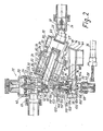
- Fig. 2 zeigt einen Vertikalschnitt durch die Armatur der Sicherheitseinrichtung.
- F ig. 1 shows a circuit diagram of a thermally controlled safety device.
- Fig. 2 shows a vertical section through the fitting of the safety device.
In Fig. 1 ist mit 10 ein mit festen Brennstoffen beheizter Kessel bezeichnet. Von dem Kessel 10 geht ein Vorlauf 12 einer geschlossenen Heizungsanlage aus, deren Rücklauf 14 zum Kessel 10 zurückgeführt ist. Die geschlossene Heizungsanlage enthält ein Ausdehnungsgefäß 16, welches die normale thermische Ausdehnung des Wassers in der geschlossenen Heizungsanlage ausgleicht. An dem Kessel 10 ist ein Sicherheitsventil 18 vorgesehen.In Fig. 1, 10 denotes a boiler heated with solid fuels. From the
Mit 20 ist eine Versorgungsleitung bezeichnet, über welche kaltes Frischwasser zugeführt werden kann. Der Druck der Versorgungsleitung 20 wird über einen Druckminderer'22 auf einen für den Kessel 10'und die Heizungsanlage zuträglichen Druck herabgesetzt, der unterhalb des Ansprechdrucks des Sicherheitsventil 18 liegt. Zwischen dem Druckminderer 22 und der Heizungsanlage liegt ein Rohrtrenner 24 in Reihe mit einem Rückflußverhinderer 26, der zwischen dem Auslaßanschluß 28 des Rohrtrenners 24 und der Heizungsanlage liegt. Der Rohrtrenner besitzt einen Durchflußanschluß 30 von großem Querschnitt und einen Steueranschluß 32 von kleinem Querschnitt. Der Durchflußanschluß 30 ist unmittelbar mit dem Auslaß des Druckminderers 22 verbunden. Der ebenfalls mit dem Auslaß des Druckminderers verbundene Steueranschluß 32 wird von einem thermisch gesteuerten Tellerventil 34 beherrscht.20 designates a supply line via which cold fresh water can be supplied. The pressure of the
Ein Temperaturfühler 36 steuert eine thermische Ablaufsicherung 38, mittels eines Stellglieds 40. Die thermische Ablaufsicherung 38 ist ein thermisch gesteuertes Ventil, welches eine mit dem System der Heizungsanlage verbundene Leitung 42 mit einem Ablauf 44 verbindet. Das Tellerventil 34 wird von dem durch das Stellglied 40 des Temperaturfühlers 36 längsverschieb- baren, zugleich den Ventilteller der thermischen Ablaufsicherung 38 steuernden Ventilstößel 46 gesteuert.A
Der konstruktive Aufbau der Armatur ist in Fig. 2 dargestellt.The structural design of the valve is shown in Fig. 2.
Der Druckminderer 22 weist ein Gehäuse 46 auf, in welches eine Membran 48 eingespannt ist, die von einer Feder 50 belastet wird. Der Raum unterhalb der Membran ist durch eine Trennwand 52 in eine Kammer 54 und eine Einlaßkammer 56 unterteilt. Ein Ventilstößel 58 eines Druckmindererventils 60, das mit einem am unteren Endes des Gehäuses 46 gebildeten Ventilsitz 62 zusammenwirkt, ist abdichtend durch die Trennwand 52 hindurchgeführt. Eine in dem Ventilstößel 58 verlaufende Kreuzbohrung 64 verbindet den Auslaß 66 des Druckminderers stromab von dem Ventil 60 mit der Kammer 54. Die Kammer 56 ist über einen Anschluß 68 mit der Versorgungsleitung 20 (Fig. 1) verbunden.The
Der Rohrtrenner 24 weist ein zylindrisches Gehäuse 70 auf, an welchem auf gegenüberliegenden Seiten der einlaßseitige Durchflußanschluß 30 und ein Auslaßanschluß 28 vorgesehen sind. In seinem unteren Endteil besitzt das Gehäuse 70 einen Auslauf 76. In dem Durchflußanschluß 30 sitzt eine Einlaßhülse 78, die an ihrem dem Durchflußanschluß 30 abgewandten Ende an der Stirnseite abgeschlossen ist und seitliche Austrittsöffnungen 80 aufweist. Auf der Einlaßhülse 78 ist ein im Gehäuse 70 geführter Ringkolben 82 mit einem hülsenförmigen, die Einlaßhülse 78 abdichtend umschließenden Schaft 84 gleitbeweglich. Der Steueranschluß 32 mündet in dem Ringraum 86 zwischen Gehäuse-70 und Ringkolben 82. Der Auslaßanschluß 28 ist von einem in das Gehäuse 70 ragenden, mit einer Innendichtung 88 versehenen Stutzen 90 umgeben. In diesen Stutzen ist der hülsenförmige Schaft 84 des Ringkolbens 82 bei einem Arbeitshub desselben abdichtend einschiebbar. Der Schaft 84 weist auf seiner Innenwandung eine Hinterschneidung 92 auf, über welche nach Einschieben des Schafts 84 in den Stutzen 90 eine Verbindung zwischen den seitlichen Austrittsöffnungen 80 der Einlaßhülse 78 und der mit dem Auslaßanschluß 28 verbundenen Bohrung des Schafts 84 hergestellt ist. Durch eine Druckfeder 94 ist der Ringkolben belastet, so daß er bei Abwesenheit eines Steuerdrucks an dem Steueranschluß 32 in der in Fig. 2 dargestellten Ruhestellung ist.The
Von dem Fühler 36 ist das Stellglied 40 und über dieses der Ventilstößel 46 gesteuert. Die thermische Auslaufsicherung enthält ein Gehäuse 96 mit einem Anschluß 98, der mit der Leitung 42 (Fig. 1) verbunden ist, und einem Anschluß 100, der mit dem Ablauf 44 in Verbindung steht. In dem Gehäuse 96 ist ein Ventilsitz 102 gebildet, auf welchem ein Ventilteller 104 aufsitzt.The
Der Ventilteller 104 ist von einer Feder 106 belastet. Er weist einen Kragen 108 auf, der abdichtend im Gehäuse 96 geführt ist. Das Gehäuse 96 weist gleichachsig mit dem Kragen 108 einen Stutzen 110 auf, in den sich an einem ringförmigen Federwiderlage 112 abgestützte Feder 106 hineinragt. In dem Stutzen 110 ist somit eine-Kammer 114 gebildet, die gegenüber dem einlaßseitigen Anschluß 98 durch den Kragen 108 und dessen Führung im Gehäuse 96 abgedichtet ist.The valve plate 104 is loaded by a spring 106. It has a collar 108 which is sealingly guided in the
An dem Gehäuse 96 sitzt gleichachsig zu dem Ventilsitz 102 und dem Ventilteller 104 das Stellglied 40 mit dem Ventilstößel 46. Der Ventilstößel 46 ist abdichtend durch den Ventilteller 104 hindurchgeführt. Er weist eine Schulter 116 auf, die nach einem bestimmten Hub des Ventilstößels 46 an dem Ventilteller 104 angreift und das Ventil gegen die Wirkung der Feder 106 aufdrückt.The
An den Stutzen 110 ist das Gehäuse 46 des Druckminderers 22 angeschlossen. Das Gehäuse 46 bildet einen Ventilsitz 116 gleichachsig zu dem Ventilsitz 62. Der Ventilstößel 46 erstreckt sich bis durch den Ventilsitz 116 hindurch und trägt an seinem Ende den Ventilteller 118 des temperaturgesteuerten Tellerventils.32 (Fig. 1). An dem Ventilstößel 46 ist weiterhin ein Ventilteller 120 angebracht, der mit einem Ventilsitz 122.zusammenwirkt und nach einem das Ventil 32 öffnenden Hub des Ventilstößels 46 den längs des Ventilstößels 46 gebildeten Durchgang 124 abschließt. Dieser Durchgang 124 steht über die Kammer 114 und eine in dem Ventilstößel 46 gebildete Bohrung 126 mit dem Auslaßs 100 der thermischen Ablaufsicherung in Verbindung.The
Der Ventilstößel 46 besteht aus zwei verschiebbar aneinander geführten Abschnitten 46a und 46b. Zwischen den Abschnitten 46a und 46b ist eine vorgespannte Feder 128 angeordnet. Dabei liegt der eine Abschnitt 46a unter der Wirkung der Feder 128 an einem Anschlag 129 des anderen Abschnitts 46b an. Wenn das Tellerventil 32 geöffnet ist und der Ventilteller 120 an dem Ventilsitz 122 anliegt, dann kann das Stellglied 40 unter Umständen den Ventilstößel 46 noch weiter nach oben in Fig. 2 schieben. Da der Ventilteller 120 an dem Ventilsitz 122 anliegt und damit die Aufwärtsbewegung des oberen Abschnitts 46b des Ventilstößels 46 begrenzt, wird die zusätzliche Bewegung des unteren Abschnitts 46a des Ventilstößels durch Zusammendrücken der Feder 128 aufgenommen. Im Normalbetrieb wirken die beiden Abschnitte 46a und 46b wie eine starre Verbindung, da die Vorspannung der Feder 128 normalerweise-nicht überschritten wird.The
Im einzelnen enthält der obere Abschnitt 46b anschließend an den Ventilteller 120 einen topfförmigen Teil 130, in welchem ein Kopfstück 132 des unteren Abschnitts 46a geführt ist. Die Feder 128 sitzt zwischen dem Boden des topfförmigen Teils 130 und dem Kopfstück 132. Der topfförmige Teil 130 bildet eine Schulter 134, an welcher eine sich am Gehäuse 46 abstützende Druckfeder 136 anlegt. Dadurch ist der Ventilstößel 46 so vorbelastet, daß normalerweise der Ventilteller 118 auf dem Ventilsitz 116 aufsitzt und das Tellerventil 32 geschlossen ist. Das Tellerventil 32 wird von dem Stellglied 40 über den Ventilstößel 46 gegen die Wirkung der Feder 136 aufgedrückt.Specifically, the upper section 46b contains, next to the
Der Steueranschluß 32 des Rohrtrenners 24 zweigt zwischen den Tellerventilen 34 und 120,122 ab. Der Druckminderer 22 ist mit seinem Druckmindererventil 60 gleichachsig zu dem Ventilstößel 46 und den Tellerventilen 34 bzw. 120,122 angeordnet. Im voll geöffnetem Zustand drückt das Druckmindererventil 60 daß den Steueranschluß 32 beherrschende Tellerventil 34 zu und das zweite Tellerventil 120,122 auf.The
Die beschriebene Anordnung arbeitet wie folgt:
- Wenn die Temperatur im Heizungssystem einen vorgegebenen Grenzwert überschreitet,
drückt das Stellglied 40über den Stößel 46zunächst das Tellerventil 34 auf. Dadurch wird Wasser vom Ausgang 66 desDruckminderers 22über den Steueranschluß 32 in die Ringkammer 86 geleitet. Der Ausgangsdruck des Druckminderers 22 wirkt auf die Stirnfläche des Ringkolbens 82 und schiebtden Ringkolben 82mit seinem Schaft 84 nach rechts unten in Fig. 2. Wenn der Schaft 84 abdichtend inden Stutzen 90 eingeführt ist, wird überden Hinterschnitt 92 die Verbindungzwischen dem Durchflußeinlaß 30 desRohrtrenners 24 und dem Auslaß 28 hergestellt.Der Rückflußverhinderer 26, der von üblicher Bauart sein kann, wird aufgedrückt, so daß eine Verbindung zwischen der Versorgungsleitung und dem Heizungssystem hergestellt ist. Beim Öffnen des Tellerventils 34 legt sich auch derVentilteller 120 an den Ventilsitz-122 an, so daß der Durchgang 124 abgesperrt ist.
- If the temperature in the heating system exceeds a predetermined limit value, the
actuator 40 first presses thepoppet valve 34 via theplunger 46. As a result, water is passed from the outlet 66 of thepressure reducer 22 into the annular chamber 86 via thecontrol connection 32. The output pressure of thepressure reducer 22 acts on the end face of theannular piston 82 and pushes theannular piston 82 with itsshaft 84 to the bottom right in FIG. 2. When theshaft 84 is sealingly inserted into thesocket 90, the connection between theFlow inlet 30 of thepipe separator 24 and the outlet 28 made. Thebackflow preventer 26, which can be of conventional design, is pushed open so that a connection between the supply line and the heating system is established. When thepoppet valve 34 is opened, thevalve disk 120 also lies against thevalve seat 122, so that the passage 124 is blocked off.
Bei weiterer Temperaturerhöhung des Heizungswassers legt sich die Schulter 116 an den Ventilteller 104 an und öffnet die thermische Ablaufsicherung 38. Jetzt kann warmes Wasser aus dem Heizungssystem über die thermische Ablaufsicherung 38 in den Ablauf 44 abfließen. Es wird also kaltes Frischwasser in die Heizungsanlage eingelassen, während warmes Heizungswasser abfließt. Die Heizungsanlage wird dadurch heruntergekühlt. Wenn die kritische Temperatur wieder unterschritten wird, schließt das Ventil 34. Der Ventilteller 120 hebt von dem Ventilsitz 122 ab. Dadurch wird die Ringkammer 86 über den Durchgang 124 mit dem Auslaß 100 der thermischen Ablaufsicherung 38 verbunden. Das Wasser aus der Ringkammer 86 kann somit abfließen, und der Kolben 82 mit dem Schaft 84 geht unter dem Einfluß der Feder 94 in die dargestellte Ausgangslage zurück. In dieser Stellung ist eine mechanische Trennung zwischen der Versorgungsleitung und dem Heizungssystem hergestellt. Eventuelles Leckwasser aus dem Heizungssystem kann nicht in die Versorgungsleitung gelangen, auch wenn der Druck in dieser aus irgend einem Grunde zusammenbrechen sollte, da austretendes Heizungswasser über die Ablauföffnung 76 in den Ablauf 44 abfließen würde.When the temperature of the heating water rises further, the shoulder 116 rests on the valve plate 104 and opens the thermal
Die beschriebene Anordnung hat noch einen weiteren Vorteil. Wenn der Druck in der Versorgungsleitung zusammenbrechen sollte, dann bedeutet dies, daß der Druckminderer 122 unter dem Einfluß der Feder 50 voll öffnet, das Druckmindererventil 60 also soweit nach unten bewegt wird, daß es das Tellerventil 34 unter Überwindung der Feder 128 zudrückt. Gleichzeitig hebt der Ventilteller 120 von dem Ventilsitz 122 ab, so daß in diesem Falle ebenfalls der Rohrtrenner 24 in die dargestellte Ruhestellung zurückkehrt. Gerade bei einem Zusammenbruch des Drucks in der Versorgungsleitung wird also eine sichere Trennung von Heizungsanlage und Versorgungsleitung gewährleistet.The arrangement described has another advantage. If the pressure in the supply line should collapse, then this means that the
Claims (6)
Priority Applications (1)
| Application Number | Priority Date | Filing Date | Title |
|---|---|---|---|
| AT81103711T ATE8814T1 (en) | 1980-05-31 | 1981-05-14 | THERMAL CONTROLLED SAFETY DEVICE FOR BOILERS IN CLOSED HEATING SYSTEMS. |
Applications Claiming Priority (2)
| Application Number | Priority Date | Filing Date | Title |
|---|---|---|---|
| DE19803020797 DE3020797A1 (en) | 1980-05-31 | 1980-05-31 | THERMALLY CONTROLLED SAFETY DEVICE FOR BOILERS IN CLOSED HEATING SYSTEMS |
| DE3020797 | 1980-05-31 |
Publications (3)
| Publication Number | Publication Date |
|---|---|
| EP0041163A2 true EP0041163A2 (en) | 1981-12-09 |
| EP0041163A3 EP0041163A3 (en) | 1982-01-20 |
| EP0041163B1 EP0041163B1 (en) | 1984-08-01 |
Family
ID=6103720
Family Applications (1)
| Application Number | Title | Priority Date | Filing Date |
|---|---|---|---|
| EP81103711A Expired EP0041163B1 (en) | 1980-05-31 | 1981-05-14 | Thermally operated safety device for boilers in closed-circuit heating plants |
Country Status (5)
| Country | Link |
|---|---|
| EP (1) | EP0041163B1 (en) |
| AT (1) | ATE8814T1 (en) |
| DE (2) | DE3020797A1 (en) |
| DK (1) | DK228881A (en) |
| NO (1) | NO151384C (en) |
Cited By (2)
| Publication number | Priority date | Publication date | Assignee | Title |
|---|---|---|---|---|
| EP0179271A2 (en) * | 1984-09-25 | 1986-04-30 | Hans Sasserath & Co Kg | Filling arrangement for filling closed liquid heating circuits |
| GB2488395A (en) * | 2011-02-22 | 2012-08-29 | Sasserath & Co Kg H | Assembly for controlling the temperature of a drinking water heater |
Citations (3)
| Publication number | Priority date | Publication date | Assignee | Title |
|---|---|---|---|---|
| DE6927453U (en) * | 1969-07-10 | 1969-10-30 | Guenter Verleger | DEVICE FOR HOT WATER CENTRAL HEATING. |
| DE1600977B2 (en) * | 1967-06-08 | 1973-10-11 | Davy-Ashmore Ag, 6000 Frankfurt | Heatable valve batteries |
| DE2713155A1 (en) * | 1977-03-25 | 1978-10-05 | Krupp Gmbh | Boiler heating system temp. control system - has hot water ejected and cold water admitted to provide lower temps. |
Family Cites Families (1)
| Publication number | Priority date | Publication date | Assignee | Title |
|---|---|---|---|---|
| DE7401779U (en) * | 1974-09-12 | Stadler J Kg | Device for thermal protection for boilers with or without temperature-controlled domestic water heater in closed water heating systems |
-
1980
- 1980-05-31 DE DE19803020797 patent/DE3020797A1/en not_active Withdrawn
-
1981
- 1981-05-14 AT AT81103711T patent/ATE8814T1/en not_active IP Right Cessation
- 1981-05-14 EP EP81103711A patent/EP0041163B1/en not_active Expired
- 1981-05-14 DE DE8181103711T patent/DE3165205D1/en not_active Expired
- 1981-05-26 DK DK228881A patent/DK228881A/en not_active Application Discontinuation
- 1981-05-29 NO NO811815A patent/NO151384C/en unknown
Patent Citations (3)
| Publication number | Priority date | Publication date | Assignee | Title |
|---|---|---|---|---|
| DE1600977B2 (en) * | 1967-06-08 | 1973-10-11 | Davy-Ashmore Ag, 6000 Frankfurt | Heatable valve batteries |
| DE6927453U (en) * | 1969-07-10 | 1969-10-30 | Guenter Verleger | DEVICE FOR HOT WATER CENTRAL HEATING. |
| DE2713155A1 (en) * | 1977-03-25 | 1978-10-05 | Krupp Gmbh | Boiler heating system temp. control system - has hot water ejected and cold water admitted to provide lower temps. |
Cited By (4)
| Publication number | Priority date | Publication date | Assignee | Title |
|---|---|---|---|---|
| EP0179271A2 (en) * | 1984-09-25 | 1986-04-30 | Hans Sasserath & Co Kg | Filling arrangement for filling closed liquid heating circuits |
| EP0179271A3 (en) * | 1984-09-25 | 1988-01-07 | Hans Sasserath & Co Kg | Filling arrangement for filling closed liquid heating circuits |
| GB2488395A (en) * | 2011-02-22 | 2012-08-29 | Sasserath & Co Kg H | Assembly for controlling the temperature of a drinking water heater |
| GB2488395B (en) * | 2011-02-22 | 2015-11-11 | Sasserath & Co Kg H | Assembly for controlling the temperature of a drinking water heater |
Also Published As
| Publication number | Publication date |
|---|---|
| DE3020797A1 (en) | 1981-12-17 |
| DE3165205D1 (en) | 1984-09-06 |
| DK228881A (en) | 1981-12-01 |
| NO151384C (en) | 1985-03-27 |
| NO151384B (en) | 1984-12-17 |
| EP0041163A3 (en) | 1982-01-20 |
| NO811815L (en) | 1981-12-01 |
| ATE8814T1 (en) | 1984-08-15 |
| EP0041163B1 (en) | 1984-08-01 |
Similar Documents
| Publication | Publication Date | Title |
|---|---|---|
| DE10256035B3 (en) | Control valve for heat exchanger or heater has valve body screwed onto seat by spindle and has pressure regulating valve with opening spring and diaphragm | |
| DE2215150A1 (en) | Thermostatic expansion valve | |
| DE102006026001A1 (en) | Safety device e.g. for water heating system, has temperature regulation element which is arranged in hot water circulation having extendable shank which rests against valve | |
| DE2917233C2 (en) | ||
| EP0041163B1 (en) | Thermally operated safety device for boilers in closed-circuit heating plants | |
| EP0179271B1 (en) | Filling arrangement for filling closed liquid heating circuits | |
| DE3632655C2 (en) | ||
| DE1019879B (en) | Valve responsive to temperature changes | |
| DE2130601C3 (en) | Gas pressure regulator | |
| EP0055813A1 (en) | Thermally operated safety-valve | |
| DE1148411B (en) | Device for regulating the cooling water circuit of internal combustion engines | |
| CH682510A5 (en) | Electrically-actuated valve. | |
| DE19856009A1 (en) | Return feed-room temperature regulating valve for central heating radiator has one of thermostats within regulating housing attached to valve housing coupled via capillary to thermo sensor in contact with return feed line | |
| DE10050207C1 (en) | Combination valve for central heating system has spring-loaded valve element operated in dependence on room temperature and temperature of heating medium | |
| DE628621C (en) | Device for automatic regulation of the gas supply to a heater | |
| EP1193434B1 (en) | Valve, in particular radiator valve | |
| DE2659456A1 (en) | GAS-HEATED CURRENT WATER HEATER | |
| DE516271C (en) | Gas pressure regulator, especially for installation in inhabited rooms, with control pressure regulator, the branch flow of which flows into the consumption line | |
| DE914697C (en) | Device for pressure reduction and overpressure protection | |
| DE3440588A1 (en) | Temperature controller for heat exchanger | |
| DE1296436B (en) | Hydraulic servomotor for control systems | |
| DE2713155A1 (en) | Boiler heating system temp. control system - has hot water ejected and cold water admitted to provide lower temps. | |
| DE3339518A1 (en) | Gas-fired heat source | |
| DE2149182B1 (en) | Thermally controllable drain valve | |
| DE2132829A1 (en) | CONTROL FITTING FOR RADIATORS OF SINGLE PIPE HEATING SYSTEMS |
Legal Events
| Date | Code | Title | Description |
|---|---|---|---|
| PUAI | Public reference made under article 153(3) epc to a published international application that has entered the european phase |
Free format text: ORIGINAL CODE: 0009012 |
|
| PUAL | Search report despatched |
Free format text: ORIGINAL CODE: 0009013 |
|
| AK | Designated contracting states |
Designated state(s): AT CH DE FR SE |
|
| 17P | Request for examination filed |
Effective date: 19811027 |
|
| AK | Designated contracting states |
Designated state(s): AT CH DE FR SE |
|
| GRAA | (expected) grant |
Free format text: ORIGINAL CODE: 0009210 |
|
| AK | Designated contracting states |
Designated state(s): AT CH DE FR LI SE |
|
| REF | Corresponds to: |
Ref document number: 8814 Country of ref document: AT Date of ref document: 19840815 Kind code of ref document: T |
|
| REF | Corresponds to: |
Ref document number: 3165205 Country of ref document: DE Date of ref document: 19840906 |
|
| ET | Fr: translation filed | ||
| PLBE | No opposition filed within time limit |
Free format text: ORIGINAL CODE: 0009261 |
|
| STAA | Information on the status of an ep patent application or granted ep patent |
Free format text: STATUS: NO OPPOSITION FILED WITHIN TIME LIMIT |
|
| 26N | No opposition filed | ||
| PGFP | Annual fee paid to national office [announced via postgrant information from national office to epo] |
Ref country code: AT Payment date: 19860514 Year of fee payment: 6 |
|
| PG25 | Lapsed in a contracting state [announced via postgrant information from national office to epo] |
Ref country code: AT Effective date: 19870514 |
|
| PG25 | Lapsed in a contracting state [announced via postgrant information from national office to epo] |
Ref country code: SE Effective date: 19870515 |
|
| PG25 | Lapsed in a contracting state [announced via postgrant information from national office to epo] |
Ref country code: LI Effective date: 19870531 Ref country code: CH Effective date: 19870531 |
|
| PG25 | Lapsed in a contracting state [announced via postgrant information from national office to epo] |
Ref country code: FR Free format text: LAPSE BECAUSE OF NON-PAYMENT OF DUE FEES Effective date: 19880129 |
|
| REG | Reference to a national code |
Ref country code: CH Ref legal event code: PL |
|
| PG25 | Lapsed in a contracting state [announced via postgrant information from national office to epo] |
Ref country code: DE Effective date: 19880202 |
|
| REG | Reference to a national code |
Ref country code: FR Ref legal event code: ST |
|
| EUG | Se: european patent has lapsed |
Ref document number: 81103711.8 Effective date: 19880601 |